Table of Contents
Advertisement
Quick Links
READ AND SAVE THESE INSTRUCTIONS
54" Ceiling Fan Owner's Manual
CF205LBQ01
CF205LGES01
CF205LGRT01
Questions, problems, missing parts: Before returning to the store, Call Customer Service
BP7574-2 HIGHPOINTE CF205L (EnSpFr) 201208.indb 1
BP7574-2 HIGHPOINTE CF205L (EnSpFr) 201208.indb 1
HIGHPOINTE LED
Model Numbers
1-888-757-7697
CF205LORB01
CF205LCVS01
U.L. Model No.: CF205L-1
12/8/20 11:52 AM
12/8/20 11:52 AM
Advertisement
Table of Contents

Related Manuals for Emerson HIGHPOINTE LED


Summary of Contents for Emerson HIGHPOINTE LED
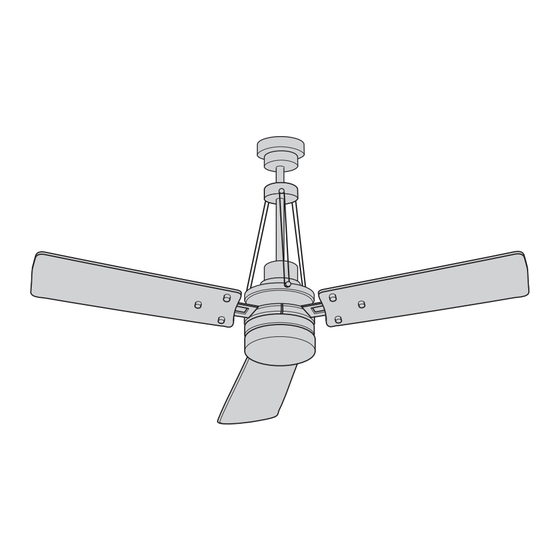
- Page 1 READ AND SAVE THESE INSTRUCTIONS HIGHPOINTE LED 54” Ceiling Fan Owner’s Manual Model Numbers CF205LBQ01 CF205LORB01 CF205LGES01 CF205LCVS01 CF205LGRT01 Questions, problems, missing parts: Before returning to the store, Call Customer Service 1-888-757-7697 U.L. Model No.: CF205L-1 BP7574-2 HIGHPOINTE CF205L (EnSpFr) 201208.indb 1 BP7574-2 HIGHPOINTE CF205L (EnSpFr) 201208.indb 1...
-
Page 2: Table Of Contents
Table of Contents Section ection Safety Instructions 8. Remote Control Procedures 1. Unpacking Instructions 9. Reverse Switch Operation 2. Electrical Requirements 10. Repair Parts 3. Ceiling Fan Assembly 11. Maintenance 4. How to Hang Your Ceiling Fan 12. Troubleshooting 5. How to Wire Your Ceiling Fan 6. -
Page 3: Unpacking Instructions
1. Unpacking Instructions PACKAGE CONTENTS WARNING Part Description Quantity Do not install or use fan if any part is damaged or missing. Call Toll-Free: Fan Motor/Housing Assembly 1-888-757-7697 Ceiling Cover Coupler Cover Fan Blades Fan Blades Flanges Decorative Blade Nuts (bagged) Hanger Bracket Lower Housing Glass... -
Page 4: Electrical Requirements
50-100 ft. Controls (Sold Separately) SW406 Wall Control (sold separately) may be used with this 54” Highpointe LED Ceiling Fan. Controls are recommended for indoor use only. 2. Electrical Requirements If your fan is to replace an existing ceiling light fixture,... -
Page 5: Ceiling Fan Assembly
3. Ceiling Fan Assembly Mount the Fan Blades to the Blade Flanges using three BLADE FLANGE #8-32 x 7/16" OVAL HEAD #8-32 x 7/16” Oval Head Screws with Lockwashers and SCREWS WITH LOCKWASHERS Three Decorative Blade Nuts (supplied) (Figure 1). (3 per blade/flange) WARNING To reduce the risk of personal injury, do not bend... - Page 6 3. Ceiling Fan Assembly (Continued) GREEN GROUND WIRE Remove the Hanger Ball by loosening the Phillips Head Set Screw in the Hanger Ball until the Ball falls freely down the Downrod (Figure 4). Remove the Pin from the Downrod, then remove the DOWNROD Hanger Ball (Figure 4).
- Page 7 3. Ceiling Fan Assembly (Continued) Align the Clevis Pin holes in the Downrod with the holes in the Motor Coupler. HAIRPIN CLIP Install the Clevis Pin and secure with the Hairpin Clip MOTOR MOTOR CLEVIS (Figure 7). COUPLER COUPLING The Clevis Pin must go through the holes in the Motor HAIRPIN CLEVIS Coupler.
- Page 8 3. Ceiling Fan Assembly (Continued) 3.11 Remove and Retain the Three Lower Decorative Rod DECORATIVE Screws, located in the Motor Housing. ROD ASSEMBLY Position the Three Decorative Rod Assemblies onto the 12" DOWNROD Motor Housing (Figure 10). The Decorative Rods must be oriented so that they LOWER lean in towards the 12”...
- Page 9 3. Ceiling Fan Assembly (Continued) 3.13 Place the Ceiling Cover over the Downrod. Then reinstall HANGERBALL the Hanger Ball (Figure 12) on the Downrod as follows. Route the Three 80” Motor Wires through the Hanger Ball and slide the Hanger Ball over the Downrod. DOWNROD Position the Pin through the Two Holes in the Downrod and align the Hanger Ball so the Pin is captured in the...
- Page 10 CAUTION CEILING To reduce the risk of injury, install the fan so that the blades are at least 7 ft. (2.1m) above the floor (Figure 14). AT LEAST AT LEAST WARNING 7 FT. (2.1m) Turning off wall switch is not sufficient. To avoid possible electrical shock, be sure electricity is turned off at the main fuse box before wiring.
-
Page 11: How To Hang Your Ceiling Fan
4. How to Hang Your Ceiling Fan (Continued) NOTE: CEILING COVER, SUPPLY WIRES AND FAN WIRES OMITTED FOR CLARITY. Carefully lift the Fan and seat the Hanger Ball/ Downrod Assembly on the Hanger Bracket that was just attached to the Outlet Box (Figure 16). Be sure the Groove in the Ball is engaged with the OUTLET Anti-Rotation Tab on the Hanger Bracket (Figure 16). -
Page 12: How To Wire Your Ceiling Fan
5. How to Wire Your Ceiling Fan If you feel that you do not have enough electrical wiring knowledge or experience, have your fan CAUTION: To reduce the risk of electrical shock, installed by a licensed electrician. disconnect the electrical supply circuit before installing the fan, light kit or receiver. - Page 13 5. How to Wire Your Ceiling Fan (Continued) NOTE: Make all wiring connections using the wire connectors supplied in the hardware kit and remote control kit. Make sure that all connections are tight, including ground, and that no bare wire is visible at the wire connectors, except for the supply circuit ground wire.
- Page 14 5. How to Wire Your Ceiling Fan (Continued) Securely connect the Receiver Black Wire (AC IN L) to the Supply Black Wire (hot) using the Wire Connector (supplied in parts bag) (Figure 20). WIRE CONNECTOR SUPPLY AND RECEIVER BLACK WIRES Figure 20 S e c u r e l y c o n n e c t t h e R e c e i v e r W h i t e W i r e (TO MOTOR N) to the Fan Motor White Wire using...
- Page 15 5. How to Wire Your Ceiling Fan (Continued) S e c u re l y co n n e c t t h e R e c ei v er B l ac k W i r e (TO MOTOR L) to the Fan Motor Black Wire using the Wire Connector (supplied in parts bag) (Figure 22).
- Page 16 5. How to Wire Your Ceiling Fan (Continued) Position the Antenna Wire on top of the Receiver. WIRE CONNECTORS While inserting the Receiver fully into the Hanger Bracket, (Tucked Inside turn Wires upward and carefully push Wires into the Outlet Box) Outlet Box, with the White and Green Wires on one side of the Outlet Box and position the Black and Blue Wires on the other side of the Outlet Box (Figure 24).
-
Page 17: Final Assembly
6. Final Assembly Engage the Fan Motor Blue Wire Connector into the LED Light Fixture Assembly Black Wire Connector (Figure 26). Engage the Fan Motor White Wire Connector into the FAN MOTOR LED Light Fixture Assembly White Wire Connector BLUE WIRE CONNECTOR (Figure 26). - Page 18 6. Final Assembly (Continued) Place the Glass into the opening of the Lower Housing, aligning the three Flat Areas on the top edge of the Glass with the three raised Dimples on the Lower Housing and turn the Glass clockwise until it stops (Figure 28). NOTE: Periodically check that the Glass is seated fully clockwise in the Lower Housing.
- Page 19 6. Final Assembly (Continued) Lift the Ceiling Cover up to the Threaded Studs and turn until Studs protrude through the Holes in the Ceiling Cover (Figure 30). Secure the Ceiling Cover in place by sliding Lockwashers over the Threaded Studs and installing the two Knurled Knobs (supplied in parts bag).
-
Page 20: Disassemble The Led Light Fixture Assembly For The No-Light Cover Installation Only
7. Disassemble the LED Light Fixture Assembly for the No-Light Cover Installation Only WARNING Turning off wall switch is not sufficient. To avoid possible electrical shock, be sure electricity is turned off at the main fuse box before wiring. All wiring must be in accordance with National and Local codes and the ceiling fan must be properly grounded as a precaution against possible electrical shock. - Page 21 7. Disassemble the LED Light Fixture Assembly for the No-Light Cover Installation Only (Continued) Disengage the Fan Motor Blue Wire Connector from the LED Light Fixture Assembly Black Wire Connector (Figure 33). Disengage the Fan Motor White Wire Connector from FAN MOTOR the LED Light Fixture Assembly White Wire Connector BLUE WIRE CONNECTOR...
-
Page 22: Remote Control Procedures
8. Remote Control Procedures Your Receiver is equipped with a preset memory feature. WARNING If the AC supply to the Receiver is powered through a Wall Switch, when the Switch is turned OFF, the Control Fan installation must be completed, including the will remember the Light Intensity and Fan Speed. - Page 23 FOR FANS WITH PULL CHAINS: For your Fan/Light Control to operate properly, the Fan Pull Chain Switch POWER INDICATOR LIGHT must be set to operate the Fan at HIGH Speed, and the Light Kit must be switched to ON position. To avoid FAN OFF BUTTON accidental Pull Chain use, shorten Chains.
- Page 24 POWER INDICATOR The Light Push Button ( ) turns the Light ON and LIGHT OFF and controls the Light Intensity (Figure 39). To vary the intensity of the Light, hold the Light Button ( ) down until the desired Light Intensity is reached, then release the Button (Figure 39).
-
Page 25: Reverse Switch Operation
9. Reverse Switch Operation Restore Electrical Power to the Outlet Box by turning the Electricity on at the Main Fuse Box. COUPLER COVER During Summer Months, run the Fan Counter-Clockwise, as you look up at it, to direct airflow downward. MOTOR REVERSE During the Winter Months, run the Fan Clockwise, as... -
Page 26: Repair Parts
10. Repair Parts PARTS BAG BP7574-2 HIGHPOINTE CF205L (EnSpFr) 201208.indb 26 BP7574-2 HIGHPOINTE CF205L (EnSpFr) 201208.indb 26 12/8/20 11:52 AM 12/8/20 11:52 AM... -
Page 27: Maintenance
11. Maintenance IMPORTANT CARE INSTRUCTIONS WARNING for your Ceiling Fan Do not use water when cleaning your ceiling fan. Periodic cleaning of your new ceiling fan is the only It could damage the motor or the blades and create the maintenance that is needed. - Page 28 SERIAL NUMBER: DATE CODE: The serial number of this fan can be found on the nameplate on top of the fan housing. The date code can be found on the carton and on top of the fan housing, stamped in ink on a white label. You should record this data above and keep it in a safe place for future use.
Need help?
Do you have a question about the HIGHPOINTE LED and is the answer not in the manual?
Questions and answers