Advertisement
Introduction
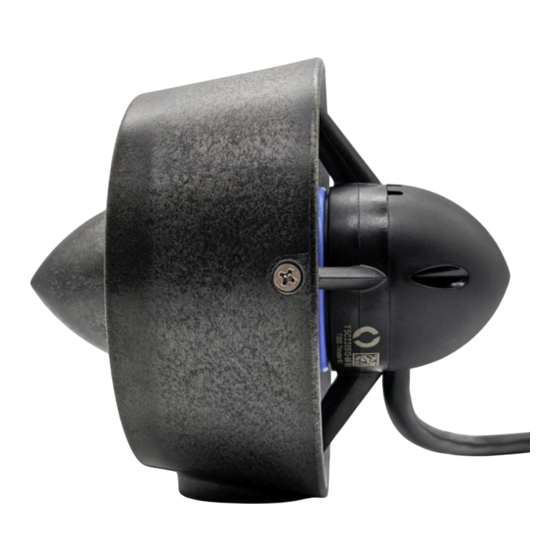
The T200 and T500 are underwater thrusters designed to be rugged, powerful,
and flexible in many applications like high-power ROVs, surface vessels, AUVs,
as well as human-carrying applications like kayaks. This guide will show you
how to operate, service, and troubleshoot your T200 or T500 thruster.
Important Safety Notes
Always practice caution when you're working with electricity in water.
Keep body parts away from the thruster inlet and outlet to avoid injury. Always practice
caution with the spinning blades of the propeller.
Do not operate the thruster for more than 10 seconds outside of water (while dry). The
bearings require water for lubrication and may be damaged if the thruster is operated for an
extended period of time while dry.
Avoid sucking seaweed or other objects into the thruster to avoid damage.
Most threadlockers are not chemically compatible with polycarbonate and will damage the
thrusters if used on any of the screws. Only use a threadlocker that is chemically compatible
with polycarbonate on the mounting screws if necessary.
A clicking sound or noisy thruster is normal, especially when operated while dry. Most noise
and vibration go away once the thruster is operated in water.
Advertisement
Table of Contents


Need help?
Do you have a question about the T200 and is the answer not in the manual?
Questions and answers