Table of Contents
Advertisement
Quick Links
Advertisement
Table of Contents

Related Manuals for Squid Ink CoPilot Max


Summary of Contents for Squid Ink CoPilot Max
- Page 1 CoPilot Max ™ Industrial Inkjet Printing System User Guide 2005482 Rev E – 201006...
- Page 2 2005482 Rev E – 201006...
- Page 3 Industrial Inkjet Printing System User Guide Revised 10/6/2020 P/N 2005482 E Copyright and Trademarks Copyright ©2019 Squid Ink Manufacturing. All rights reserved. All trademarks and brand names are the property of their respective owners. Squid Ink Manufacturing 7041 Boone Avenue North...
- Page 4 2005482 Rev E – 201006...
-
Page 5: Table Of Contents
Understanding Safety Notifications ................10 General Precautions ....................10 Introduction ..................... 11 General System Description ..................11 System Components ....................11 CoPilot Max Controller Dimensions ..................13 CoPilot Max Printhead Dimensions ..................14 System Specifications ....................15 Software Specifications ....................16 Options ........................17 Mounting Hardware ..................... - Page 6 Distance from Substrate ......................31 Mounting to a Floor Stand ....................32 Conveyor Mounting Bracket ....................33 Spring-Loaded Printhead Bracket ..................34 Rotating or Tilting the Printhead ..................35 Cable Connections ...................... 36 Connecting Photocell Trigger ....................36 Connecting Optional Encoder ....................36 Custom Triggering Device ....................37 Printhead Data Cable ......................39 Connecting a Second Printhead ..................40 Connecting Additional Printing Systems ................41...
- Page 7 Preparing a Printhead for Shipping (Solvent-Based, Oil-Based, and UV-Based) ..108 Troubleshooting ..................109 Parts List ....................111 CoPilot Max Oil-Based Assembly ................111 CoPilot Max Solvent-Based Assembly ..............112 CoPilot Max UV-Based Assembly ................114 CoPilot Max Replaceable Parts................. 116 Controller Exploded View ..................
- Page 8 CoPilot Max System Updates ............... 119 Warranty Statement ................121 Warranty Statement ....................121 Warranty Period ......................121 Printheads ......................... 121 Repairs ........................121 Print Quality ......................121 Shipping Policy......................121 Exclusions ......................... 121 Warranty Procedures ....................122 Within 45 Days of Invoice ..................122 45 Days To 1 Year from Invoice (6 Months for Printheads) ........
-
Page 9: Safety
Use only Squid Ink Manufacturing ink or other Squid Ink Manufacturing approved fluids. • The Squid Ink CoPilot Max Printer uses an ink cartridge system. Do not open or use the • ink supply cartridge in any way other than normal installation. -
Page 10: Understanding Safety Notifications
Indicates a hazardous situation which, if not avoided, could result in property damage only. General Precautions When installing, operating, and maintaining the CoPilot Max, observe these cautions. WARNING: Health Hazard Some inks may be a health hazard with prolonged exposure. Ensure that the area has adequate ventilation. -
Page 11: Introduction
The CoPilot Max printing system is designed to print superior quality high-resolution characters on a variety of porous surfaces. The CoPilot Max printing system consists of a CoPilot Max Controller with a touch screen user interface and up to two CoPilot Max Printheads that use Squid Ink CoPilot Max ink cartridges. - Page 12 Do not throw this card away. The card contains a serial number required for downloading Orion and connecting the CoPilot Max printing system. If there is no card, you can still download Orion and connect to a single Printer. If there are problems, call Customer Service at 800-877-5658.
-
Page 13: Copilot Max Controller Dimensions
Introduction CoPilot Max Controller Dimensions Top View Bottom View Side View Rear View 2005482 Rev E – 200611... -
Page 14: Copilot Max Printhead Dimensions
Introduction CoPilot Max Printhead Dimensions Top View Side View Front View Rear View Bottom View 2005482 Rev E – 201006... -
Page 15: System Specifications
Introduction System Specifications Print Technology Piezo impulse Printhead technology Print Speed Up to 110 fpm at 300 DPI horizontal resolution Up to 220 fpm at 150 DPI horizontal resolution Message Length Substrate length up to 48 inches Vertical Print Resolution 360 DPI Horizontal Print Resolution 300 DPI (0–110 feet per minute) -
Page 16: Software Specifications
Introduction Software Specifications Time and Date Multiple formats including: 1,2,4, -digit year, 1,2-digit month, 3 letter month, custom month string, 1 letter day of month (Korean), 2-digit day of month, 1-digit day of week, 1,3 letter day of week, 2- digit week of year, 3 digit Julian year, 1 letter hour, (a-x), 2-digit hour 12 or 24, 2-digit minute, 2 digit second, 1,2 letter meridians (A/P, AM/PM), custom week string. -
Page 17: Options
Introduction Options Part Number Description Purpose Dependent STARTER KIT Includes ink, cleaner and flush, Printhead on ink wipes, hand cleaner, and latex gloves. 1505154 DUAL UV LED CURING SYSTEM – Cures and dries UV-based inks. ACTIVE 1604177 ENCODER ASSEMBLY KIT For operation with variable speed conveyors. -
Page 18: Mounting Hardware
Introduction Mounting Hardware Squid Ink offers a variety of Floor Stands and Conveyor Mounts for a range of unique situations. Contact your Squid Ink distributor for guidance on which stand best suits your needs. NOTE: Stands and mounts do not come with CoPilot Max Controllers or Printheads. - Page 19 Introduction FLOOR STAND Top View ASSEMBLY, 1HD CP MAX (Part Number 2005041) Accommodates: 1 CoPilot Max Controller 1 Printhead • Spring-Loaded Mount protects Printhead from bumps by products passing on conveyor. FLOOR STAND Top View ASSEMBLY, 2HD CP MAX (Part Number 2005042)
- Page 20 Introduction FLOOR STAND Top View ASSEMBLY, 2HD CP MAX (Part Number 2005082) Accommodates: 1 CoPilot Max Controller 2 Printheads • Can print 2 different messages at once. 2005482 Rev E – 201006...
-
Page 21: Conveyor Mounting Systems
Introduction Conveyor Mounting Systems Conveyor Mounts attach directly to the conveyor. Squid Ink offers several Conveyor Mounts. Please consult with your Squid Ink distributor for guidance on which mount will best meet your needs. CONVEYOR MOUNT Top View (Part Number 2005051) - Page 22 Introduction CONVEYOR MOUNT Top View (Part Number 2005062) Accommodates: 1 CoPilot Max Controller 2 Printheads • Can print 2 different messages at once • Spring-Loaded Mount protects Printheads from bumps by products passing on conveyor. CONVEYOR MOUNT Top View (Part Number 2005071)
-
Page 23: Installation And Setup
Installation and Setup Installation and Setup General Recommendations Material Handling The most critical item for consistently superior quality printing is material handling. This is an area controlled by the customer and the installer. Always use adequate conveyor product guides, and ensure that they are installed and maintained properly. Incorrect or inconsistent product handling will cause print quality problems, maintenance problems, and could lead to Printhead damage. -
Page 24: Work Area
Vibration CoPilot Max print engines do not de-prime easily. The print engines are tolerant of being bumped by passing products and normal conveyor vibrations. However, sustained, long- term vibration may lead to erratic print performance. In cases where the conveyor is especially vibration-prone, the entire printing system can be mounted on an optional stand (see “Floor Stand Mounting Systems”... -
Page 25: Printhead Overview
Installation and Setup Printhead Overview Printhead Front Components Nozzle Face Printhead Rear Components Ink Cartridge Purge Button Power Indicator Light Data Cable Port Ink Drain Line 2005482 Rev E – 200611... -
Page 26: Controller Overview
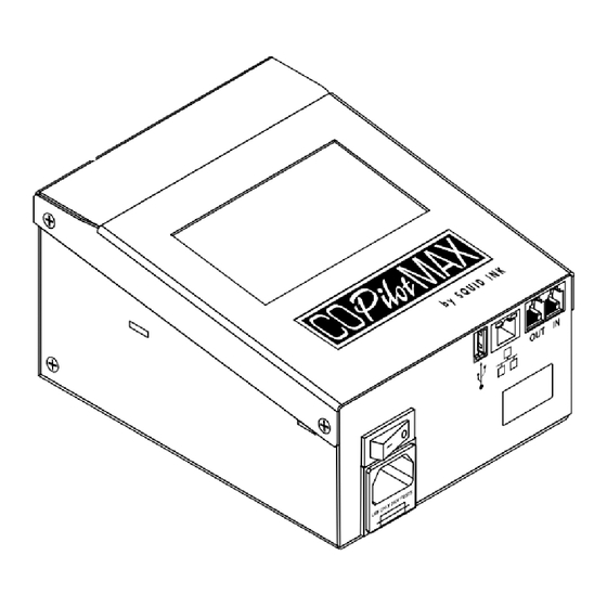
Installation and Setup Controller Overview Controller Front View Touch Screen Photocell/Encoder IN Photocell/Encoder OUT to Daisy Chain Printers Network Power Switch Label Power Cord Fuse Controller Rear View Printhead 1 Data Cable Printhead 2 Data Cable 2005482 Rev E – 201006... -
Page 27: Mounting
Each installation is unique and Squid Ink Manufacturing cannot anticipate customer requirements for attaching Mounting Brackets to the production line. Squid Ink recommends using a CoPilot Max Floor Stand Mounting System (see “Floor Stand Mounting Systems” on page 18) or CoPilot Max Conveyor Mounting Assembly (see “Conveyor Mounting Systems” on page 21) for mounting the CoPilot Max printing system. -
Page 28: Mounting The Controller
Installation and Setup Mounting the Controller There are two M6 mounting holes located on the bottom of the CoPilot Max Controller. Use these holes and the supplied Mounting Screws to attach the Controller to the Mounting Bracket. NOTICE: Use only the supplied Mounting Screws to attach the CoPilot Max Controller to the Mounting Brackets. -
Page 29: Mounting A Photocell
Installation and Setup Mounting a Photocell A Photocell (Part Number 1602018) can be mounted to the CoPilot Max Printhead using a Photocell Mounting Bracket. Mount the Photocell on the upstream side of the Printhead so that it detects the product before it reaches the Printhead. - Page 30 Installation and Setup Choosing the Correct Photocell Mounting Bracket To ensure optimal performance of the Photocell, it is important to select the correct Photocell Mounting Bracket for the intended situation. The matrix below shows the various Bracket Assembly options. Situation Straight / Spring- Conveyor...
-
Page 31: Distance From Substrate
The recommended distance between the nozzle plate and the printed surface is 0.125 inches (3.2 mm). Throw distances greater than 0.125 inches are possible, but print quality may be affected. Recommended Distance from Substrate: " 0.125 (3.2 mm) CoPilot Max Printhead Substrate Printhead Nozzle 2005482 Rev E – 200611... -
Page 32: Mounting To A Floor Stand
Installation and Setup Mounting to a Floor Stand When using a Floor Stand Mount, screw the bottom of the Controller to the upper shelf bracket, and attach the Printhead to the arm of the Mount. Front View Rear View (Conveyor Side) (User Side) Controller Printhead... -
Page 33: Conveyor Mounting Bracket
Installation and Setup Conveyor Mounting Bracket When using a Conveyor Mounting Bracket, screw the bottom of the Controller to the upper shelf bracket, and attach the Printhead to the arm of the Mount. Controller Printhead Conveyor Mounting Bracket Conveyor Mounting Assembly (See “Conveyor Mounting Systems”... -
Page 34: Spring-Loaded Printhead Bracket
34 Mounting Options Spring-Loaded Printhead Bracket A spring-loaded bracket (Part Number 2004570) can be added to either the Floor Stand Mounting System or the Conveyor Mounting Assembly to provide a bumper that prevents damage to the Printhead from products passing on the conveyor. Front View Rear View Top View... -
Page 35: Rotating Or Tilting The Printhead
The Printhead can be mounted in a rotated or tilted orientation. This is useful when printing on an incline conveyor or vertical web. The Printhead can be rotated 90° counterclockwise (CoPilot Max logo facing upward) or 45° clockwise (Squid facing upward) when viewed from the rear of the Printhead. Do not rotate the Printhead 90°... -
Page 36: Cable Connections
An Encoder is essentially a wheel that touches the conveyor belt and sends electronic pulses to the CoPilot Max Controller with real time information on the distance that the conveyor has moved at any given instant, regardless of changes in conveyor speed. -
Page 37: Custom Triggering Device
Installation and Setup 37 Encoder Connect the optional Encoder and Photocell trigger to an RJ12 Adapter Cable (Part Number 2003864). Connect the Adapter Cable to the IN connection on the back of the Controller. IN Connection RJ12 Adapter Cable Photocell Encoder Controller Rear Panel Custom Triggering Device... - Page 38 38 Installation and Setup NOTE: Site-specific or unusual devices should only be connected by trained and qualified personnel. If in doubt, contact your Squid Ink distributor. On the RJ12 Connector, connect Pin 4 to an NPN sinking open-collector source with Pin 5 acting as ground.
-
Page 39: Printhead Data Cable
CAUTION: Connect the CoPilot Max Printhead only to a CoPilot Max Controller. Connecting a CoPilot Max Printhead to another CoPilot Max Controller may damage the Printhead and void the warranty. The front of the CoPilot Max Controller contains two data connections labeled PRINTHEAD 1 and PRINTHEAD 2. Printhead Data Cable Connections Connect a Data Cable to the PRINTHEAD 1 port. -
Page 40: Connecting A Second Printhead
40 Installation and Setup CoPilot Max Printhead 1 CoPilot Max Controller Printhead Data Cable The Data Cable also carries power from the Controller to the Printhead. There is no power switch on the Printhead. The Printhead starts when the Controller is turned on. -
Page 41: Connecting Additional Printing Systems
However, the number of Printers connected through a single triggering device is limited by the specific installation and use. Other Squid Ink printing systems may also be connected downstream from the Controller. For example, a CoPilot, an AutoPilot, and an SQ-2 printing system could be attached to a single triggering device. -
Page 42: Optional Low Ink Warning Devices
An optional Low Ink Warning Beacon (Part Number 2003927) can be connected to the CoPilot Max Controller USB port. An optional Audible Low Ink Warning Device (Part Number 2003975) is also available. An optional Four Port USB Hub (Part Number 2004242) can be used to connect both of these low ink warning devices at once. -
Page 43: Connecting To A Desktop Computer
Installation and Setup 43 Connecting to a Desktop Computer A desktop computer can be connected to the CoPilot Max Controller, enabling the user to create and download messages using Orion software. To connect to a desktop computer, connect an Ethernet Cable to the Ethernet port on the Controller and to the Ethernet port on the computer. -
Page 44: Connecting To A Local Area Network
44 Installation and Setup Connecting to a Local Area Network A Local Area Network (LAN) can be connected to the CoPilot Max Controller, allowing the user to connect multiple Controllers to a network-connected PC running Orion software. To connect to a Local Area Network, plug the Network Cable into the network connection on the CoPilot Max Controller. -
Page 45: Usb Port
Installation and Setup 45 USB Port The USB port located on the back of the CoPilot Max Controller can be used to connect to a variety of USB-supported devices such as a wireless network adapter antenna, Low Ink Alarm Beacon, scanner, or removable USB storage device. The maximum current available on the USB port is 900 mA. -
Page 46: Optional Four Port Usb Hub
Low Ink Warning USB Hub Beacon Power Supply USB Drive USB Wireless Adapter Four-Port USB Hub USB Cable to Controller USE ONLY 250V FUSES SQ-CPMAX-00022 CoPilot Max Controller Optional Four Port USB Hub (Part Number 2004242) 2005482 Rev E – 201006... -
Page 47: Power Supply
2. Verify that the Power Switch is in the OFF position. 3. Attach the supplied Power Cord into the power cord receptacle. 4. Plug the Power Cord into a properly wired and grounded electrical outlet. CoPilot Max Controller Power Switch Power Cord Port... -
Page 48: Ink Supply
48 Installation and Setup Ink Supply Ink and fluids are supplied to the CoPilot Max Printhead using a 500 ml cartridge ink system. The Ink Cartridge has been manufactured and labeled to ensure that the correct ink is used. CAUTION: Use only ink and fluid cartridges from Squid Ink Manufacturing. Using unauthorized fluids may damage the equipment, cause a safety hazard, and will void the warranty. - Page 49 Installation and Setup 49 A small tab located above the Ink Fitting prevents the wrong type of ink from being installed in the Printhead. The Ink Fitting on the front of the Ink Cartridge is color-coded to correspond with the ink type.
-
Page 50: Installing The Ink Or Fluid Cartridge
CoPilot Max Printhead Shipping Cover If using the CoPilot Max for the first time, or if it has been idle for an extended period, commission the Printhead before use (see “Commissioning the Printhead” on page 52). To install an Ink Cartridge or Flush Cartridge, snap the 500 ml Cartridge into position. Verify that the Cartridge is fully seated in the Printhead. -
Page 51: Initial Startup
When all components have been properly mounted and connected, the CoPilot Max can be started. To start the CoPilot Max printing system, turn the Power Switch located on the front of the Controller to the ON position. -
Page 52: Commissioning The Printhead
52 Installation and Setup Commissioning the Printhead Commissioning is a process which must be done before use if: The printing system is new • • The system has been idle for an extended period The system has been in storage •... - Page 53 Installation and Setup 53 Internal Flush Lint-Free Wipe Fluid Cartridge Uncapped Drain Tube Waste Collection Trays 5. On the rear of the Printer, press and hold the Purge Button until flush fluid exits the Drain Tube and the Nozzle Face. 6.
- Page 54 54 Installation and Setup The Printhead is now commissioned and ready to print. NOTE: If missing jets appear in the print path, an additional purge and wipe may be required. 2005482 Rev E – 201006...
-
Page 55: Operation
2. Verify that nothing is covering the Nozzle Face before priming or printing. 3. Turn the Power Switch located on the back of the Controller to the ON position. 4. After the power is turned on, the CoPilot Max printing system goes through a brief startup sequence lasting approximately one minute. -
Page 56: Interface Button Overview
56 Operation Interface Button Overview Button Function Start or Stop Select Start to start printing. Select Stop to stop printing. Printing Zoom Zoom Screen Screen to view the message at an enlarged or Select the reduced size. Message Screen Select the Message Screen to display a list of messages available for printing. - Page 57 Operation 57 Switch between the Settings Page One Screen and the Settings Page Two Screen. Information. Set line speed. Set distance from Printhead to trigger (Photocell). Show distance in inches. Show distance in centimeters. Set print direction. Set print direction: left to right. Set print direction: right to left.
- Page 58 Eject the USB drive. Reset production counter to zero and ink supply to “full.” Reset ink supply to “full.” Reset production counter to zero. Select the CoPilot Max Settings Screen. Printhead temperature. Open the Wireless Connect Screen. 2005482 Rev E – 201006...
- Page 59 Operation 59 Access or dismiss the on-screen keyboard. Disconnect from Wifi. Open the Bluetooth Connect Screen. Access or dismiss the on-screen keyboard. Recalibrate the Touchscreen. Access a remote database server. Search the remote database. Show or change the current date. Show or change the current time.
- Page 60 60 Operation Use a static IP address. Sleep Select the Sleep button to place the Printer into Sleep Mode. This is a soft shutdown. Sleep is useful for long periods of idle time. Touch the Controller Touchscreen to restart. If the Spit Mode is turned on, the Printer continues to spit ink while in Sleep Mode (see “Spit Settings”...
-
Page 61: Home Screen
Operation 61 Home Screen The Home screen contains the following: A preview of the current message • • The name of the current message Product count • • Ink status Printing status • If a USB drive is plugged into the USB port at startup, the Printer will automatically display the USB Load Screen. -
Page 62: Zoom Screen
62 Operation Zoom Screen On the Home Screen, select the Zoom button to open the Zoom Screen. The 1 and 2 buttons indicate the active Printhead. Select Full Message Width , 75%, and 100% to zoom in and out of the message. The current zoom setting button is available. -
Page 63: Message Screen
Message Screen Delete Select Delete to remove a selected message from the CoPilot Max Controller. Deleting the message only deletes the message copy in the CoPilot Max Controller. It does not delete the message from Orion. 2005482 Rev E – 200611... -
Page 64: Message Screen Remote Server
64 Operation Message Screen Remote Server If the Printer is using a remote database server to load messages for printing, enter a message ID. Select APPLY to load the message for printing. When the message is loaded, a green checkmark is briefly displayed in the lower right corner of the screen. If the connection fails, an error message is briefly displayed. -
Page 65: Settings Screen
Operation 65 Settings Screen The Settings Screen contains two pages of printer configuration settings. Select to switch between Settings Page One Screen and Settings Page Two Screen. Settings Screen – Page 1 Settings Screen – Page 2 Following describes the settings accessible through the Settings Screen and what their functions are. -
Page 66: Line Speed
Line Speed Screen Encoder Timeout The Encoder Timeout is the amount of time in seconds that the CoPilot Max Printer waits for a signal after the Encoder Wheel stops spinning. If the conveyor stops for any reason while printing a message or between messages, the Printer stops looking for an Encoder signal after the specified time. - Page 67 Operation 67 Select APPLY to save changes. Select BACK to return to the previous screen. 2005482 Rev E – 200611...
-
Page 68: Distance To Trigger
Distance to Trigger is the amount of distance between the trigger (usually a Photocell) and the Jets on a Printhead. For CoPilot Max, Squid Ink recommends mounting the Photocell approximately 6" (15 cm) upstream from the Printhead, and setting the “Distance to Trigger”... -
Page 69: Print Direction
Operation 69 Print Direction Print Direction is the direction of the production line relative to the position of the Printer when viewed from behind the Printhead. To set the Print Direction for the selected Printhead, do the following: 1. Select the button that corresponds to the direction you want to print. 2. -
Page 70: Encoder
70 Operation Encoder Use the Encoder Divider Screen to set the divider value if an optional Encoder is installed. Use the Plus (+) or Minus (-) buttons or the slider to increase or decrease the encoder divider value. Encoder Screen Encoder Reset Select this button to reset the encoder divider to the default value of 3 (300 DPI) or 6 (150 DPI). -
Page 71: Repeat Trigger
Operation 71 Repeat Trigger The Repeat Trigger controls whether SquidConnect printing is active or inactive using SquidConnect Pin 6. Refer to the SquidConnect User Guide for more information. If the SquidConnect Dongle is not installed, this option is not available. If SquidCheck is active, this option is not available. - Page 72 72 Operation If using a switch box to activate the trigger, select Photocell Repeat Trigger SquidConnect Photocell Active If not using a switch box to activate the trigger, select Screen Repeat Trigger SquidConnect Screen Active 2005482 Rev E – 201006...
-
Page 73: Counters
Operation 73 Counters Use the Counters Screen to set the current value of each printer counter in the current message. Counters can be used to track many items, such as the number of boxes or pallets printed on. Counters Screen To change the counter value, use the Plus (+) or Minus (-) buttons or the slider to increase or decrease the counter. -
Page 74: Spit Settings
Ink Nozzles. Use the Spit Settings Screen to configure settings for Spit Mode. Spit Mode is not used on the CoPilot Max with oil-based inks. Spit Settings Screen Spit Mode There are four spit modes: OFF: If selected, turns the Spit Mode off. - Page 75 The Printer will continue to spit throughout the idle period to reduce the likelihood of ink drying and clogging the system. Spit Settings Screen If using solvent-based inks, contact your Squid Ink distributor for guidance on the appropriate spit settings to use. 2005482 Rev E – 200611...
-
Page 76: Barcode Validation
76 Operation Barcode Validation An optional Squid Check Vision System (Part Number 2003850) can be used to verify barcodes. For details on connecting the Squid Check Vision System, please refer to the Squid Check manual. This button is not available on older versions of the software or if a Barcode Scanner is not detected or connected. -
Page 77: Usb Load
Operation 77 USB Load The USB Load Screen provides functions for data management and Printer updates. The USB Load Screen opens automatically when a USB device is connected. NOTE: The USB format must be FAT32. If system updates are available on an installed USB drive, this button becomes active. Select this button to install the updates. -
Page 78: Reset
78 Operation Reset Use the Reset Screen to reset the production counter to zero and the ink level to full. Reset Screen 1. Select the Reset Ink Printhead button to reset the ink supply to full. 2. On the Reset Screen, select Head 1 or Head 2. 3. -
Page 79: Copilot Max Settings
Operation 79 CoPilot Max Settings Select to change CoPilot Max Ink Cartridges during printing or to change print resolution for a higher or lower maximum print speed. Ink Cartridge Swap Temporarily stop ink flow from the selected Ink Cartridge when changing Ink Cartridges during printing without running out of ink. - Page 80 80 Operation 4. When finished, select APPLY to save changes. Select BACK to return to the previous screen. Enable Faster Print Speed Use this function to change print resolution mode. Do one of the following: Select 300 DPI to print in the default high-resolution printing mode at print speeds •...
-
Page 81: Printhead Temperature
Operation 81 Printhead Temperature The Printhead Temperature button is used to display the current temperature for the Printhead in Fahrenheit or Celsius. Printhead Temperature Screen Printhead Temperature - Fahrenheit 2005482 Rev E – 200611... - Page 82 82 Operation Printhead Temperature - Celsius The appropriate environmental temperature range for the Printhead during operation is 34-104 °F (1-40 °C). 2005482 Rev E – 201006...
-
Page 83: Calibrating The Touchscreen
4. After the center box has been touched, a “Calibration Completed” message is displayed. The Controller returns to the Settings screen. 5. Restart the CoPilot Max Controller for calibration to take effect. NOTE: If the screen is out of calibration and cannot be recalibrated using the Controller, select Reset Calibration on the Printer Configuration Tools tab in Orion. -
Page 84: Remote Database Server
84 Operation Remote Database Server The Remote Database function allows the CoPilot Max Controller to connect to a remote database. Refer to the Orion Software User Guide for more information on creating database messages. Select the Database button to open the Remote Database screen. - Page 85 Operation 85 Multicast Tab The Multicast Address IP setting and UDP port will match the communication settings for the DB server created using Orion. Normally, the settings will be automatically populated with the default value and should not have to be changed. If the address is changed in Orion, it will also have to be changed at the Printer.
-
Page 86: Set Date
86 Operation Set Date Use the Set Date function to set the date in the Printer. This can be the date that printing is taking place, an expiration date, or any other date desired in the message. 1. Use the Plus (+) or Minus (-) buttons to select the date format. 2. -
Page 87: Set Time
Operation 87 Set Time Use the Set Time function to set the current time in the Printer. This is typically set to the current time to track time of packaging. The time is displayed in hours, minutes, and seconds. To change the time value, select the Plus (+) or Minus (-) buttons for the hours, minutes, and seconds to increase or decrease the time. -
Page 88: Peak Encoder Speed
88 Operation Peak Encoder Speed Select the Peak Encoder button to display the top line speed recorded by the Encoder in feet per minute (FPM). Peak Encoder speed is used to determine what speed the Printer requires to be able to print accurately. -
Page 89: Custom Keyboard
Orion for use with User Data, use this screen to select the keyboard. Custom Keyboard Screen Standard Keyboard Selected When available, the CoPilot Max Controller uses the standard CoPilot Max keyboard Custom Keyboard Unselected When the Standard Keyboard button is available, the Custom Keyboard button is not available. - Page 90 90 Operation Custom Keyboard Example 2005482 Rev E – 201006...
-
Page 91: Language
Operation 91 Language The CoPilot Max Printing System supports eight languages: U.S English German Mandarin Chinese Spanish Korean Japanese Russian Polish To select a language, do the following: 1. On Settings Screen Two, select the Language icon. 2. In the Language window, select the desired language. - Page 92 92 Operation 4. To open Language Screen Two, select the More button. The CoPilot Max Controller displays the selected language. Language Screen 2 5. Restart the Controller for the language change to take effect. 2005482 Rev E – 201006...
-
Page 93: Static Ip Address
Operation 93 Static IP Address A static IP address can be assigned to the CoPilot Max Controller. NOTE: When assigning a new IP address, work with the local IT Administrator to ensure that the new address does not conflict with existing devices. -
Page 94: User Data
User data is data that is provided by the user. If user data is contained in the current message, the User Data button on the CoPilot Max Touchscreen is available. The User Data function allows messages that contain user data to be edited directly from the CoPilot Max Touchscreen or USB Keyboard. -
Page 95: Wireless Interface
The CoPilot Max Controller can be connected to a wireless network or Bluetooth keyboard. A tablet or desktop computer cannot connect directly to the CoPilot Max Printer using a wireless network. Instead, a Linksys Model EA4500 Wireless Router or Wireless USB Adapter must be used. - Page 96 96 Operation NOTE: The Wireless Router must support Wireless Protected Access (WPA) Encryption. Older standards are not supported. 4. On Settings Screen Two, select the Wireless button 5. On the WIFI Screen, select the Scan button . The Printer detects the available wireless networks.
- Page 97 When successfully connected to the wireless network, the Connected button is available and the IP address for the CoPilot Max Controller is displayed. The password is not displayed after the Controller successfully connects. To end the wireless connection, select the Disconnect button before removing the Wireless USB Adapter from the CoPilot Max USB port.
- Page 98 98 Operation NOTE: Restart the Printer when changing from wireless to Ethernet or from Ethernet to wireless. 2005482 Rev E – 201006...
-
Page 99: Temperature Warning Screens
The CoPilot Max checks the Printhead temperature every few minutes to detect if it is overheating. For CoPilot Max Oil Systems, if a temperature over 130 °F (54.4 °C) is detected for the interface, a full-screen warning is displayed. Tap the Touchscreen to dismiss the full-screen warning. - Page 100 100 Operation If a temperature over 140 F (60 °C) is detected, a critical warning screen is displayed, and printing is disabled. Tap the Touchscreen to dismiss the full-screen warning. Following a critical temperature warning, allow the Printheads to cool. ...
-
Page 101: Powering Off
Operation 101 Powering Off To power off the CoPilot Max printing system, turn the Power Switch on the front of the Controller to the OFF position. CoPilot Max Controller Power Switch For a soft shutdown, which reduces time needed to boot up, select the Sleep mode... - Page 102 102 Operation 2005482 Rev E – 201006...
-
Page 103: Maintenance
Nozzle Plate. Ensure that the external cleaning fluid is compatible with the ink and Printhead being flushed. Use only non-abrasive lint-free wipes (Part Number 2005470) and appropriate Squid Ink Manufacturing fluids to clean the Nozzle Face. Always wipe in one direction without applying any finger pressure. -
Page 104: External Cleaning
External Cleaning • The outside surfaces of the CoPilot Max printing system can be wiped clean with a clean cloth and flushed with Squid Ink approved cleaning fluid. Gently wipe the components clean. Never immerse the components in water or cleaning fluids. -
Page 105: Flushing The Printhead
NOTICE: Ensure that the flush fluid is compatible with the ink and Printhead being flushed (see “Inks and Fluids” on page 118). Use only non-abrasive lint-free wipes (Part Number 2005470) and appropriate Squid Ink Manufacturing fluids to clean the Nozzle Face or flush the Printhead. - Page 106 106 Maintenance 5. Hold a non-abrasive lint-free wipe gently in front of and under the Nozzle Face and press the Purge Button for about 30 seconds. 6. Remove the Flush Cartridge from the Printhead. 7. Hold a non-abrasive lint-free wipe gently in front of the Nozzle Face and press the Purge Button for about 30 seconds or until fluid no longer flows from the Nozzle Face.
-
Page 107: Preparing A Printhead For Storage (Solvent-Based And Uv-Based Only)
NOTICE: Ensure that the flush fluid is compatible with the ink and Printhead being flushed. Use only non-abrasive lint-free wipes (Part Number 2005470) and appropriate Squid Ink Manufacturing fluid to clean the Nozzle Face or flush the Printhead. To Prepare a CoPilot Max Printhead for Storage 1. -
Page 108: Preparing A Printhead For Shipping (Solvent-Based, Oil-Based, And Uv-Based)
108 Maintenance 8. Hold a non-abrasive lint-free wipe gently in front of and under Nozzle Face and press the Purge Button until clean and clear fluid comes out of all the Printhead Nozzles. NOTE: It is important to remove all ink before adding storage fluid. This is essential to prevent residual ink from settling into crevices, which can cause problems later. -
Page 109: Troubleshooting
Troubleshooting 109 Troubleshooting Problem Possible Cause Solution Print quality distorts Line noise, brownouts, or Install a good-quality AC occasionally or system locks blackouts may be affecting power line conditioner or the quality of the AC power Uninterruptible Power supply to the system. Supply (Part Number 2004199) to ensure clean electrical supply. - Page 110 110 Troubleshooting 2005482 Rev E – 201006...
-
Page 111: Parts List
Parts List 111 Parts List CoPilot Max Oil-Based Assembly CoPilot Max Oil-Based Assembly (Part Number 2005400) 2005482 Rev E – 200611... -
Page 112: Copilot Max Solvent-Based Assembly
112 Parts List CoPilot Max Solvent-Based Assembly CoPilot Max Solvent-Based Assembly (Part Number 2005401) 2005482 Rev E – 201006... - Page 113 Parts List 113 Item Number Part Number Description 055020-052 SCRW-FH 6-32X1/4 SST PH 065151-001 SCRW-FH M4X8MM PH 095995-002 1440011 PCB ASSEMBLY, CP MAX 1440013 CP MAX MEZZANINE BOARD 1705038 2001430 SCREW-PHP, M3X6, W/EXT WASHER 2003536 SCREW-PHP, M2X4 2003539 SCREW-FHP, M3X16, BLACK ZINC 2003570 SCREW-THREAD FORM, 2-28X5/8 2003610...
-
Page 114: Copilot Max Uv-Based Assembly
114 Parts List CoPilot Max UV-Based Assembly CoPilot Max UV-Based Assembly (Part Number 2005402) 2005482 Rev E – 201006... - Page 115 Parts List 115 Item Number Part Number Description 055020-052 SCRW-FH 6-32X1/4 SST PH 065151-001 SCRW-FH M4X8MM PH 095995-002 1440011 PCB ASSEMBLY, CP MAX 1440013 CP MAX MEZZANINE BOARD 1705038 2001430 SCREW-PHP, M3X6, W/EXT WASHER 2003536 SCREW-PHP, M2X4 2003539 SCREW-FHP, M3X16, BLACK ZINC 2003570 SCREW-THREAD FORM, 2-28X5/8 2003610...
-
Page 116: Copilot Max Replaceable Parts
116 Parts List CoPilot Max Replaceable Parts There are no field-replaceable parts in the CoPilot Max or the CoPilot Max Controller. Do not open the Printer or the Controller on site. Below are individual external parts that the user may need to replace or add to their CoPilot Max system. -
Page 117: Controller Exploded View
Parts List 117 Controller Exploded View 2003909 2003271 1603532 200327 2006065 1603530 2006065 2001430 2003920 1603529 2003972 1603576 2003271 2003974 2003923 2003916 2003907 2003271 2005482 Rev E – 200611... -
Page 118: Inks And Fluids
118 Parts List Inks and Fluids Internal External Floor and Storage Ink Base Flush Cleaning Fluid Work Area Fluid Fluid (Nozzle Area) Cleaner SI-PZ1060 SI-PZ1043 SI-PZ1053 Part #: 2101140 NOT near Printhead SI-PZ1900 (black) SI-PZ1943 SI-PZ1053 (Mineral Oil Free) SI-PZ1901 (red) 2101947 NOT near SI-PZ1902 (blue) -
Page 119: Copilot Max System Updates
CoPilot Max System Updates 119 CoPilot Max System Updates Occasionally software and firmware updates will become available from Squid Ink Manufacturing. Software and Printer System Firmware can be updated from a desktop computer using Orion™. Periodically check to see if updates are available. Refer to the “Installing System Updates”... - Page 120 120 CoPilot Max System Updates 2005482 Rev E – 201006...
-
Page 121: Warranty Statement
Printheads are warranted for 6 months from the date of shipment from Squid Ink. Use of inks, flush fluids, and cleaning fluids that are not obtained from Squid Ink, or which do not meet Squid Ink’s manufacturing specifications and have written approval of Squid Ink void the warranty on Printheads. -
Page 122: Warranty Procedures
Defective products will be replaced or repaired as promptly as possible. Within 45 Days of Invoice For warranty questions that take place within 45 days of the original invoice, Squid Ink will allow cross-shipment of a replacement component to an end-user customer or Squid Ink distributor. -
Page 123: Disclaimer Of Damages
Disclaimer of Damages REGARDLESS OF WHETHER ANY REMEDY SET FORTH HEREIN FAILS OF ITS ESSENTIAL PURPOSE, IN NO EVENT WILL SQUID INK MANUFACTURING, INC. BE LIABLE FOR ANY SPECIAL, CONSEQUENTIAL, INDIRECT OR SIMILAR DAMAGES, INCLUDING LOST PROFIT OR LOST OPPORTUNITIES OF ANY TYPE ARISING OUT OF THE USE OR INABILITY TO USE THESE PRODUCTS EVEN IF SQUID INK MANUFACTURING, INC. - Page 124 124 Warranty Statement 2005482 Rev E – 201006...
-
Page 125: Technical Support
Squid Ink reseller or Squid Ink Technical Support. Toll-Free Phone: 800-877-5658 Phone: 763-795-8856 Fax: 763-795-8867 Email: info@squidink.com Web: www.squidink.com Thank you for your purchase of Squid Ink products. We are pleased to be a part of your marking and coding needs. 2005482 Rev E – 200611...
Need help?
Do you have a question about the CoPilot Max and is the answer not in the manual?
Questions and answers