Table of Contents
Advertisement
Quick Links
Advertisement
Table of Contents

Subscribe to Our Youtube Channel
Related Manuals for Squid Ink ALFAMAQ CoPilot 128


Summary of Contents for Squid Ink ALFAMAQ CoPilot 128
- Page 1 CoPilot 128/256 Industrial Inkjet Printing System User Guide Rev Q 2003978...
- Page 2 Rev Q 2003978...
- Page 3 User Guide Revised 12/4/2018 P/N 2003978 Rev Q Copyright and Trademarks Copyright ©2018 Squid Ink Manufacturing. All rights reserved. All trademarks and brand names are the property of their respective owners. 1a. Cda. Jacarandas #14 Col. El Vergel, Iztapalapa. Ciudad de México C.P.
- Page 4 Rev Q 2003978...
-
Page 5: Table Of Contents
Contents: Safety ......................9 Introduction ..................... 10 General System Description ..................10 System Components ....................10 System Specifications ....................12 Software Specifications ....................13 Options ........................14 Installation and Setup ................15 General Recommendations ..................15 128 Printhead Overview ....................16 256 Printhead Overview .................... - Page 6 Message Screen Remote Server ................54 Settings Screen ......................55 Line Speed: .........................56 Distance to Trigger: ......................58 Print Direction: ........................59 Encoder Divider: ........................60 Repeat Print: ........................61 Counters: ..........................62 Spit Function: ........................63 Peak Encoder Speed: ......................65 USB Load: ...........................66 Reset: ..........................67 Ink Status ..........................68 Print Engine Alignment: .......................69 Calibrate Touchscreen ......................70...
- Page 7 Piezo Printing System ................115 Product Warranty .................. 115 Customer Support ................. 118 Rev Q 2003978...
- Page 8 Safety Rev Q 2003978...
-
Page 9: Safety
• Use only Squid Ink Manufacturing ink or other Squid Ink manufacturing approved fluids. • The Squid Ink CoPilot 128/256 printer can use an ink cartridge or an ink bag system. Do not open or puncture the ink supply cartridge or bag in any way other than normal installation. -
Page 10: Introduction
10 Introduction Introduction General System Description The CoPilot 128/256 printing system consists of a controller with an integrated user interface, and up to two 128 or two 256 printheads with cartridge or bag ink systems. The CoPilot printing system is designed to print superior quality high-resolution characters on a variety of porous and non-porous surfaces. - Page 11 Introduction 11 If you have purchased an optional level of Orion™ that allows a you to connect to multiple printers, you will find upon opening the CoPilot 128/256 shipping carton a “DOWNLOAD INSTRUCTIONS” card. Do not throw this card away! It contains a serial number that will be needed for downloading the Orion™...
-
Page 12: System Specifications
Substrate Capabilities Porous or non-porous applications. Ink Capabilities Solvent or oil-based inks. Ink System Ink system utilizes Squid Ink Manufacturing 500ml cartridge or pigmented bag ink systems. Low Ink Indicator message alert on touchscreen. Agency Certifications TUV and CE certified (Pending). -
Page 13: Software Specifications
Introduction 13 Software Specifications Time & Date Multiple formats including: 1,2,4, digit year, 1,2-digit month, 3 Letter months, custom month string, 1 letter day of month (Korean), 2-digit day of month, 1-digit day of week, 1,3 letter days of week, 2-digit week of year, 3-digit Julian year, 1 letter hour, (a-x), 2-digit hour 12 or 24, 2-digit minute, 2-digit second, 1,2 letter meridian (A/P, AM/PM), custom week string. -
Page 14: Options
14 Introduction Options Encoder For operation with variable speed conveyors. Bar Code Laser Scanner Allows scan and print message retrieval. Starter Kit Includes ink, cleaner and flush, printhead wipes, hand cleaner, and latex gloves. Rev Q 2003978... -
Page 15: Installation And Setup
In cases where the conveyor is especially vibration-prone, the entire printing system can be mounted on a stand. Optional stands are available from Squid Ink for these applications. Maintenance Access When planning the installation, allow for easy access to the printheads so that priming and cleanup can be done conveniently. -
Page 16: 128 Printhead Overview
16 Installation and Setup 128 Printhead Overview Printhead Mounting Bracket Data Cable from Controller Ink Line Photocell Mounting Fitting Bracket Holes Nozzle Face Note: The data cable for the 128 printhead is permanently attached to the back of the printhead. It does not unplug. Rev Q 2003978... -
Page 17: Printhead Overview
Installation and Setup 17 256 Printhead Overview Data Cable Connection Mounting Ink Line Bracket Fitting Nozzle Faces Photocell Mounting Bracket Holes Rev Q 2003978... -
Page 18: Controller Overview
18 Installation and Setup Controller Overview Photocell/Encoder Out to Second CoPilot System Photocell/Encoder In Power Network Switch Connection Port Fuse Power Cord Receptacle Low Ink 1 Connect Data Cable Connection for Printhead 1 Data Cable Connection for Printhead 2 Low Ink 2 Connect Rev Q 2003978... -
Page 19: Mounting
Installation and Setup 19 Mounting Each installation is unique and Squid Ink Manufacturing cannot anticipate customer requirements for attaching mounting brackets to the production line. Several mounting systems are available for the Copilot 128/256 printing system. Follow the instructions for the specific mounting system ordered with your printer. -
Page 20: Controller
Controller Mounting Screws Attention! Use only the supplied mounting screws to attach the touchscreen controller to the mounting brackets. Using mounting screws other than that supplied by Squid Ink Manufacturing can result in damage to the controller assembly. Rev Q 2003978... - Page 21 Installation and Setup 21 Printhead Mounting Assembly Cartridge Ink System Controller Mounting Bracket CoPilot 128/256 Main Components on Mounting Bracket Rev Q 2003978...
-
Page 22: Printhead Height
22 Installation and Setup Printhead Height The height of the printhead relative to the height of the ink reservoir is very important. Ensure that the lowest nozzle on the printhead face is at the same level as the top of the ink reservoir or ink bag system. - Page 23 Installation and Setup 23 Printhead Height Relative to Ink Reservior or Ink Pan Sideshooter Mode 128 Jet 256 Jet Printhead Printhead Printhead Printhead Face Face Ink Reservior: The middle of the jet on the printhead must be at the same level as the top of the ink reservior. The ink reservior/ink pan height relative to the printhead height is very important.
- Page 24 24 Installation and Setup Printhead Height Relative to Ink Reservior or Ink Pan Downshooter Mode In the downshooter mode, all the jets are horizontal, so they are all at the same level. The ink reservior/ink pan height relative to the printhead height is very important.
-
Page 25: Photocell
Installation and Setup 25 Photocell A photocell can be mounted directly to the CoPilot 128 and 256 printheads using the supplied mounting bracket and mounting screws. The photocell should be mounted on the downstream side of the printhead so it will see the product first. Printhead Photocell Photocell... -
Page 26: Distance From Substrate
26 Installation and Setup Distance from Substrate As a general rule the closer the printhead is to the surface to be printed (substrate), the better the print quality. We recommend keeping the printed surface within 1/8” (3.2mm) from the nozzle plate. While throw distances greater than 1/8” are possible, print quality may be affected. -
Page 27: Rotating And Tilting The Printhead
Installation and Setup 27 Rotating and Tilting the Printhead If a downshooter configuration is desired, the head angle and height must be adjusted. To print straight down, align the printhead with the red indicator mark in the 6 o’clock position. The printhead arm assembly should be raised to the corresponding red mark at the very top of the vertical post. - Page 28 28 Installation and Setup The printhead/bracket assembly needs to be moved to other locations on the mounting post, along with the collar, so that the ink height relative to the printhead orifice remains printing properly. Locate top of bracket near this scribe mark Locate top of bracket near this...
-
Page 29: Data Cable Connections
Installation and Setup 29 Data Cable Connections Connecting Photocell Trigger to Controller Connect the photocell signal cable to the “IN” connection on the back of the controller touch panel. Connection “IN” Controller Back Panel Photocell Connecting an Optional Encoder to the Controller Connect the optional encoder and photocell trigger to the RJ12 adapter cable. -
Page 30: Custom Triggering Device
30 Installation and Setup Custom Triggering Device Some applications may require the use of a site-specific triggering device. Use the following Pin Assignments on the RJ12 CoPilot connector to install a custom triggering device. Attention! Site-specific or unusual devices should only be connected by trained and qualified personnel. -
Page 31: Printhead Data Cable
Installation and Setup 31 Printhead Data Cable Attention! Ensure that the controller power switch is turned OFF and the controller is disconnected from the power source when connecting a printhead. Do not “Hot Plug” the printheads. On the front of the Touch Screen controller box there are data connections for two (2) printheads. - Page 32 32 Installation and Setup Controller Reservoir Low Ink Signal Wire Printhead Data Cable Printhead 1 Printhead and Low Ink Connections Rev Q 2003978...
-
Page 33: Connecting A Second Printhead
Installation and Setup 33 Connecting a Second Printhead Attention! Ensure that the controller power switch is turned OFF and the controller is disconnected from the power source when connecting a second printhead. Do not “Hot Plug” the printheads. To connect a second printhead connect the printhead data cable to “PRINTHEAD 2” and connect the other end to the designated printhead. -
Page 34: Connecting A Second Copilot Printing System
Other Squid Ink printing systems can also be connected downstream from the controller. For example, there could be a CoPilot, AutoPilot, and a Streamline printing system all slaved off the single triggering device. -
Page 35: Connecting An Optional Low Ink Warning Light
Installation and Setup 35 Connecting an Optional Low Ink Warning Light An optional low ink warning light (part number 2003927) can be connected to the CoPilot controller. The low ink warning light is useful for alerting operators that ink is running low before missed prints begin to occur when the printer starts running out of ink. -
Page 36: Connecting To A Desktop Pc
36 Installation and Setup Connecting to a desktop PC To connect to a desktop PC, connect an Ethernet cable to the Ethernet port Desktop PC on the Copilot controller and to the Ethernet port on the PC. Ethernet Cable Connecting to a Local Area Network The network connection is located on the controller. -
Page 37: Usb Port
Installation and Setup 37 USB Port There is a USB port located at the back of the Copilot controller. The USB port can be used for a variety of USB supported devices such as a WIFI adapter antenna, low ink alarm light, scanner, removable USB storage device, etc. -
Page 38: Optional Four Port Usb Hub
38 Installation and Setup Optional Four Port USB Hub There is only a single USB port located on the CoPilot controller however the CoPilot is not limited to a single USB device. The optional four port USB hub (Part Number 2004242) can provide three points of entry for USB supported devices. -
Page 39: Power Supply
Installation and Setup 39 Power Supply There is a power cord receptacle located on the back of the controller touch panel. Attach the supplied power cord into the power cord receptacle. Make sure the power switch is in the off position and plug the power cord into a properly wired and grounded electrical outlet. -
Page 40: Ink Supply
One ink system (cartridge or bag) can supply two printheads if they are mounted in the down shooter configuration. Caution! Use only authorized ink and fluid cartridges from Squid Ink Manufacturing. Use of unauthorized fluids may damage the equipment and cause a safety hazard. - Page 41 Installation and Setup 41 Remove the foil seal from a new cartridge of ink. Install the ink by placing the cartridge in the ink system at a right angle and rotating clockwise. The cartridge will thread down into the receptacle and seat into the ink reservoir. Ink will then fill the reservoir. Ink Cartridge Priming Bulb Cutout...
- Page 42 42 Installation and Setup The Ink Reservoir contains a short tube that allows air to flow into the ink reservoir during normal use. This tube is capped for shipping purposes, but the cap should be removed for normal operation. If the system is moved to a new location, be sure to cap the vent tube to prevent ink from escaping.
- Page 43 Installation and Setup 43 Reservoir Vent Tube (Must Be Uncapped for Operation) Printhead Cartridge In-Line Check Valve Ink Line from Reservoir Reservoir Ink Line Fitting In Low Ink Signal Wire to Low Ink Connection on CoPilot Controller Connecting Ink System to the Printhead Rev Q 2003978...
-
Page 44: Bag Ink System
44 Installation and Setup Bag Ink System To install a bag ink system, you will first have to attach the ink tray to the printer stand. The following illustration shows an assembled bag ink system mounted on a typical print stand. - Page 45 Installation and Setup 45 You will have to make an ink line with female fittings on each end to run from the ink tray to the back of the printhead. When the ink bag tray has been mounted at the correct height and the ink supply line has been connected to the printhead, connect the ink bag to the fitting in the ink tray.
-
Page 46: Important! Handling Of Ink Bags
46 Installation and Setup Printhead Ink Bag Tray Ink Line Ink Line Fitting Ink Line Fitting Bag Ink Tray Connected to the Printhead IMPORTANT! Handling of Ink Bags: 1. When using pigmented inks, Initial agitation, if required (each morning after down time for an evening), should be done with the bag disconnected. -
Page 47: Operation
Scratches will result in diminished print quality. The printhead is NOT warranted against scratches on the orifice plate. Squid Ink’s non- abrasive wipes are included in the CoPilot Start-Up Kit or they can be ordered as a separate item (P/N:2007021). -
Page 48: Priming The Bag Ink System
48 Operation Priming the Bag Ink System After the ink bag is attached, you will have to prime the ink system to get the ink flowing into the printhead. Prime the printer by gently but firmly pushing down on the ink bag while holding a non-abrasive lint-free printhead wipe in front of the printhead face. -
Page 49: Power Up
Operation 49 Power up When all the components have been properly mounted and connected, you are ready to power up the CoPilot and begin printing. Tip! It is a good time to double check your installation at this time. Make a quick inspection to ensure all the components have been securely mounted, and all data and power cables are properly seated and connected. -
Page 50: Home Screen
50 Operation When startup is complete, the Home screen will display on the touchpanel. Home Screen The Home Screen is displayed when power up is complete. The Home Screen will show: • A preview of the current message • The name of the current message •... - Page 51 Operation 51 Message Function Buttons Message Preview Name Product Counter Zoom Button Printing Status Connection Type Printhead(s) not Status Current Time WiFi or Intranet Connected and Date There are five function buttons located along the left edge of the Home Screen. Stop/Start Printing: Press the “Stop”...
-
Page 52: Zoom Function
52 Operation Sleep: Press the “Sleep” button to enter the printer into a sleep mode. Sleep is useful for long periods of idle time. This is a “Soft Shutdown”. Touch the screen to restart. Attention! If the Spit Function is turned on the printer will continue to spit ink while in the “Sleep”... -
Page 53: Message Screen
Operation 53 Message Screen The “Message Screen” will display a list of available messages. To select a message for printing, touch and highlight the desired message and press the “Apply” button. Use the Up and Down arrows to scroll through the message list. Reminder! Messages are created using the Orion™... -
Page 54: Message Screen Remote Server
54 Operation Message Screen Remote Server If the printer is using a Remote Server Database to load messages for printing, the message ID must be entered. After entering the Message ID, select the “Apply” icon to load the desired message for printing. When the message is loaded, a green checkmark will briefly appear in the lower right corner of the screen. -
Page 55: Settings Screen
Operation 55 Settings Screen The “Settings” screen contains buttons for configuring the printer. There are two pages of Settings Screens. Use this button to toggle between page one and page two. Settings Screen Page One (No USB Present) Settings Screen Page One (With USB Present) Rev Q 2003978... -
Page 56: Line Speed
56 Operation Settings Screen Page Two Line Speed: Use the “Line Speed” screen to set a static line speed for the printer. Line speed units are in Feet per Minute. When using an encoder, the line speed is ignored while the encoder is switched on, and therefore doesn’t have to be set. - Page 57 Operation 57 Line Speed Using an Encoder: If you are going to use an encoder to dictate line speed select the Encoder “ON” button and select the “Apply” button. Encoder Timeout (seconds) The Encoder timeout is the amount of time the CoPilot Printer will wait for a signal after the encoder wheel stops spinning.
-
Page 58: Distance To Trigger
58 Operation Distance to Trigger: Distance to Trigger is the amount of distance between the trigger (photocell) and the jets on a printhead. To change the print delay either, click the Plus or Minus button for the selected printhead to increase or decrease the print delay, or move the slider bar in the plus or minus direction and select the “Apply”... -
Page 59: Print Direction
Operation 59 Print Direction: Print Direction is the direction of the production line relative to the position of the printer when viewed from behind the printhead. To set the Print Direction for the selected printhead (one or two), select the button that corresponds to the direction you want to print. -
Page 60: Encoder Divider
60 Operation Encoder Divider: Use the “Encoder Divider” screen to set the divider value for an optional encoder if installed. Use the plus (+) or minus (-) buttons or the slider bar to increase or decrease the encoder divider value. Encoder Reset Button: Selecting this button will reset the encoder divider to the default value of 13 (205 dpi). -
Page 61: Repeat Print
Operation 61 Repeat Print: Use the repeat button to select if the repeat print command will be hard- triggered from the photocell, or soft-triggered from the home screen. Repeat Trigger with Soft Trigger Selected Repeat Trigger with Photocell Selected Rev Q 2003978... -
Page 62: Counters
62 Operation Counters: Use the “Counters” screen to set the current value of each printed counter in the current message. To change the counter value, select the Plus “ ” or Minus “ ” button to increase or decrease the counter. Select “Apply” to set the current counter value. Rev Q 2003978... -
Page 63: Spit Function
Operation 63 Spit Function: When turned on, the printhead will spit a small quantity of ink at pre- determined intervals. The spit function is useful when printing with fast-drying solvent based inks to keep the ink from drying and clogging in the ink nozzles. Use the “Spit Settings”... - Page 64 64 Operation Spit Quantity (Columns) Define the quantity of the spit mode by selecting the number of columns the printhead will spit each time. Spit Period (Seconds) The “Spit Period” in Seconds is the time between spits. Spit Delay (Milliseconds) The “Spit Delay”...
-
Page 65: Peak Encoder Speed
Operation 65 Peak Encoder Speed: Select the peak Encoder button to open a window that will display the top speed that the encoder has recorded. To set a lower top speed, the Peak Encoder Speed will have to be reset using the Reset button. Reset Button Top Speed Example: an operator wants to slow the product line speed, and inadvertently turns the... -
Page 66: Usb Load
66 Operation USB Load: The “USB Load” screen provides functions for data management and printer updates. The USB button in the Settings Screen will be disabled if there is no USB present. The USB Load screen will automatically open if a USB device is plugged in. -
Page 67: Reset
Operation 67 Reset: Use the “Reset” screen to reset the production counter to Zero and the ink Level to full. Select the Reset Ink printhead to reset the ink supply to full. In the “Reset Screen” select Head 1 or Head 2. Select the Counter reset button to reset the production counter to zero. -
Page 68: Ink Status
68 Operation Ink Status The Ink Status button is used to select the type of ink system. The Bag ink system will monitor ink usage by the number of ink drops used. The cartridge ink system will monitor ink usage via a float located in the ink reservoir. Note: Generally, one ink system is used to supply one printhead. -
Page 69: Print Engine Alignment
Operation 69 Print Engine Alignment: This feature works with Copilot 256 printhead. The alignment value is used to fine tune the horizontal alignment of the two print engines in a 256 head. The unit is measured in print columns. Typically, there are 200 columns per inch. -
Page 70: Calibrate Touchscreen
70 Operation Calibrate Touchscreen This button is used to calibrate the touchscreen. Normally the graphics on the touchscreen won’t be out of sync with the corresponding functions. However, if there are problems selecting icons, recalibrating the touch screen may help. To Recalibrate the Touchscreen: Select the Calibrate Screen Icon from the Settings screen. - Page 71 Operation 71 After the center box has been clicked, a brief screen calibration completed message will display and the controller will return to the “Settings” screen. Screen Calibration utility Touch the center of black square boxes to calibrate Screen Calibration completed, returning to previous menu 1999 Power-cycle the CoPilot controller.
-
Page 72: Remote Database Server
72 Operation Remote Database Server The remote database function allows the printer to be connected to a remote database message that has been created in Orion™. Select the Database icon to open the Remote Database screen. Remote Mode Start/Stop Remote Server Multicast ‘... - Page 73 Operation 73 Remote Server Tab In the Remote Server screen, use the search icon to locate the database server for the message(s) you wish to print. After selecting the Search icon, a drop-down list of connected servers will appear. Select the desired server and select the “Apply”...
- Page 74 74 Operation Multicast Tab The Multicast Address IP setting and UDP Port will match the communication settings for the DB server created using the Orion™ message creation software. Normally the settings will be automatically populated with the default value and shouldn’t have to be changed.
-
Page 75: Set Date
Operation 75 Set Date: Use the “Set Date” function to set the current date residing in the printer. The date is displayed in the Year, Month, and Day. To change the date, select the Plus “ ” or Minus “ ” button to increase or decrease the date. Select apply to set the date. Set Time: Use the “Set Time”... -
Page 76: Custom Keyboard
76 Operation Custom Keyboard: Select to Open the Custom Keyboard Screen. If a custom keyboard has been created in Orion™ for use with User Data, use this screen to select the keyboard. Standard Keyboard Selected. When this icon is highlighted the CoPilot will use the standard CoPilot keyboard. - Page 77 Operation 77 Text 1 Prompt squid ink ‘ Shift 1669 Example of Custom Keyboard Created in Orion™ Tip! If the keys on a custom keyboard are all blank, the newly created keyboard probably wasn’t sent to the printer from Orion™. Go back to the Orion™...
-
Page 78: Language
78 Operation Language: The Copilot Printing System supports seven languages. The “Language” Icon can be found on “Settings Screen Two”. • U.S. English • German • Mandarin Chinese • Spanish • Korean • Japanese • Russian Select the Language Icon from the Settings Screen Two to open the Language window. Select the desired language then select “APPLY”. -
Page 79: Static Ip Address
Operation 79 Static IP Address: A static IP address can be assigned to the CoPilot Controller. The IP Address Icon can be found on “Settings Screen Two”. Select the IP Address Icon from Settings Screen Two to open the IP Address window. Static IP 192.168.0.50 255 255 255 0... -
Page 80: User Data
80 Operation User Data: If User Data is contained in the current message, the “User Data” button on the CoPilot touchscreen will be activated. The User Data function allows messages that contain User data to be edited directly from the CoPilot Onscreen Touch Pad, USB Keyboard or Scan and Print. -
Page 81: Wireless Interface
You do not need to install the software that comes with these devices. These drives are already built into the CoPilot Printing System. You may purchase these devices from your favorite computer outlet or directly from Squid Ink manufacturing. After the Wireless Adapter has been installed power up the CoPilot Controller in the normal fashion. -
Page 82: Wifi
Attention! A tablet or desktop computer cannot connect via WIFI directly to the CoPilot printer. A WIFI router that supports multicast must be used. Squid Ink sells and recommends using a Linksys Model EA4500. Other routers are currently not supported. - Page 83 Operation 83 If there is a security code for the desired network, use the onscreen keyboard to enter the password. After entering the correct password select the Onscreen Keyboard button to close the Keyboard. Select “Apply” to connect to the network. When successfully connected the “CONNECTED”...
-
Page 84: Bluetooth
84 Operation Bluetooth: Select this button to open the Bluetooth settings screen. Pair Follow the onscreen steps one and two. After you have pressed the “Pair” button, type some test characters on your keyboard. They should appear in the “Test Entry” box. Once they do, the keyboard is connected. Rev Q 2003978... -
Page 85: Description Of Copilot 128/256 Touchscreen Buttons
Operation 85 Description of CoPilot 128/256 Touchscreen Buttons Button Function Return to the Home Screen Stop Printing Start Printing Open the Message Files Screen Open the Settings Screen Places the CoPilot Printer in Sleep Mode Apply Current Settings and Values Return To Previous Screen Set Print Delay in the Tools Screen Select Print Direction in the Tools Screen... - Page 86 86 Operation Button Function Open Bluetooth Connect Screen Recalibrate the Touchscreen Remote Database Server Show/Change Current Time Show Change Current Date Encoder: Open the Encoder Dialogue Box Spit Settings Open the Counters Dialogue Box Set Line Speed Connect to USB: Only Enabled if USB Present Copy Messages from Printer to USB Copy Messages from USB to Printer Reset: Select to Reset Production Counter to Zero and Ink...
- Page 87 Operation 87 Button Function Reset Ink Supply to Full User Data: Active if Current Message Contains User Data Open the “Ink Status” Settings Screen Ink Status: Count Drops Float Only Selected Ink Status: Count Drops Float Only Not Selected Ink Status: Count Drops Selected Ink Status: Count Drops Not Selected Ink Status: Combine Ink Bags Selected Ink Status: Combine Ink Bags Not Selected...
- Page 88 88 Operation Button Function Select to open the Language Screen Select to open the IP Address Screen Toggle between Settings Page One and Page Two Printhead not Connected. This icon will display on the home screen if no printheads are detected Rev Q 2003978...
-
Page 89: Powering Off
Powering Off 89 Powering Off There is no special sequence for powering down the Copilot 128/256 Printing System. Simply press the power switch to the OFF position to turn off the printer. Power Switch For a soft shutdown select the “Sleep” mode. Rev Q 2003978... -
Page 90: Mounting Options
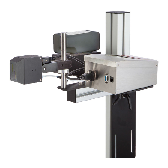
90 Mounting Options Mounting Options Floor Stand Printing System Mounted with Cartridge Ink System Printing System Mounted with Bag Ink System Typical Floor Stand Mounting Rev Q 2003978... -
Page 91: Conveyor Mounting Bracket
Mounting Options 91 Conveyor Mounting Bracket 2004920 2001148 2002059 (KIT) 1147 Typical Conveyor Mounting Kit number 2005940 Rev Q 2003978... -
Page 92: Maintenance
Cleaning External Externally the CoPilot 128/256 printing system can be wiped clean with a Squid Ink approved cleaning fluid or flush and a clean cloth. Gently wipe the components clean. Never immerse the components in water or cleaning fluids. -
Page 93: Flushing The Printhead
Maintenance 93 Flushing the Printhead Caution! If you fail to use the prescribed fluid for flushing, it may clog and ruin the print engine. If priming the print engine does not bring all jets back to the printing state, it may be necessary to flush the print engine. - Page 94 94 Maintenance Syringe Filter Ink Tube with Fitting Twist the end of the filter onto the syringe. This joint should be snug, but not too tight. Over-tightening the filter will block the syringe so no fluid will come out. If you notice difficulty purging, loosen the filter slightly.
- Page 95 Maintenance 95 Insert the fitting protruding from the syringe and filter into the input fitting in the tube leading to the print engine (see below). Waste Container With firm pressure, flush the fluid in the syringe through the ink line and out through the print engine.
-
Page 96: Parts List
96 Parts List Parts List CoPilot 128/256 Replaceable Parts Main Components Part Number Description 2001067 Printhead 128 2001135 Printhead 256 2003955 CoPilot 128 Touchpanel Controller 2003956 CoPilot 256 Touchpanel Controller 2001065 Cartridge Ink System Porous 2001066 Cartridge Ink System Non-Porous 2001159 Bag Ink System Porous 2001160... -
Page 97: Mounting Hardware
Parts List 97 Mounting Hardware Mounting Bracket Assembly 2004920 Rev Q 2003978... - Page 98 98 Parts List Printhead Mounting Assembly 2001148 Rev Q 2003978...
- Page 99 Parts List 99 Bag Ink System Mounting Bracket Assembly 2001161 Rev Q 2003978...
- Page 100 100 Parts List Floor Stand Mounting Assembly One Arm 2001132 (Two Arm 2004921) Rev Q 2003978...
- Page 101 Parts List 101 Conveyor Bracket Mounting Assembly 2002059 Rev Q 2003978...
-
Page 102: Ink Systems
102 Parts List Ink Systems 2001065 Cartridge Ink System Assembly, Porous Rev Q 2003978... - Page 103 Parts List 103 2165 2001065 Cartridge Ink System Porous Rev Q 2003978...
- Page 104 104 Parts List 2001066 Cartridge Ink System Non-Porous Rev Q 2003978...
- Page 105 Parts List 105 2166 2001066 Cartridge Ink System Non-Porous Rev Q 2003978...
- Page 106 106 Parts List 2001159 Bag Ink System Porous Rev Q 2003978...
- Page 107 Parts List 107 2001160 Bag Ink System Non-Porous Rev Q 2003978...
-
Page 108: Printheads
108 Parts List Printheads 2001067 Printhead Assembly 128 Rev Q 2003978... - Page 109 Parts List 109 2001135 Printhead Assembly 256 Rev Q 2003978...
-
Page 110: Component Dimensions
110 Component Dimensions Component Dimensions All dimensions are shown in inches. Controller Rev Q 2003978... -
Page 111: 128P/256 Pn 2003902
Component Dimensions 111 128P/256 PN 2003902 Controller, Exploded View 2003909 2003271 (4) 1603532 1603530 2006065 (4) 2001430 (4) 1603529 2003920 2003972 1603576 2003923 2003974 2003916 (4) 2003907 2003271 (2) 1912 Rev Q 2003978... - Page 112 112 Component Dimensions Dimensions are shown in inches. 128 Printhead 256 Printhead Rev Q 2003978...
-
Page 113: Copilot 128/256 System Updates
System Updates 113 CoPilot 128/256 System Updates Occasionally software and/or firmware updates will become available from Squid Ink Manufacturing. Software and Printer System Firmware can be updated from the desktop via Orion™. Periodically check to see if updates are available. - Page 114 In the unlikely event there is a problem remove the USB device containing the update and power the printer off and on (reboot) and retry installing the update. If the problem persists, call Squid Ink Manufacturing Technical Support. Rev Q 2003978...
- Page 115 Squid Ink. Printheads Use of inks, flush fluids, and cleaning fluids that are not obtained from Squid Ink, or which do not meet Squid Ink’s manufacturing specifications and have written approval of Squid Ink void the warranty on printheads. Use of a printhead wipe material not approved by Squid Ink voids the warranty on printheads.
- Page 116 Return Material Authorization number and may return the defective item to Squid Ink. Squid Ink will analyze the product and, if indeed found to be defective, we will, at our option, replace or repair the item. If the item is found not to be eligible for warranty, you will be notified and may decide on disposition.
- Page 117 LIABLE FOR ANY SPECIAL, CONSEQUENTIAL, INDIRECT OR SIMILAR DAMAGES, INCLUDING LOST PROFIT OR LOST OPPORTUNITIES OF ANY TYPE ARISING OUT OF THE USE OR INABILITY TO USE THESE PRODUCTS EVEN IF SQUID INK MANUFACTURING, INC. HAS BEEN ADVISED OF THE POSSIBILITY OF SUCH DAMAGES.
- Page 118 Squid Ink reseller or Squid Ink Technical Service at one of the numbers listed below. Toll-Free 800-253-2627 Phone Phone (55) 5426-4137 E-mail info@alfamaq.mx www.alfamaq.mx Thanks again for your purchase of Squid Ink products. We are pleased to be a part of your marking and coding needs. Rev Q 2003978...
- Page 119 Rev Q 2003978...
- Page 120 Rev Q 2003978...
Need help?
Do you have a question about the ALFAMAQ CoPilot 128 and is the answer not in the manual?
Questions and answers