Table of Contents
Advertisement
Quick Links
WL4FW FIREWALL
MANUAL
Waterlogic Trading LTD,
WLI Trading Limited, Second Floor, Suite 4, Beacon Court, Sandyford, Co. Dublin, Ireland
Tel: + 353 (0) 1293 1960
Fax: + 353 (0) 1293 1052
For Technical Support Email: support@waterlogicsupport.zendesk.com
WLI (UK) LTD – Global Headquarters Grenfell Road, Maidenhead, Berkshire, SL6 1HN, United Kingdom
Advertisement
Table of Contents
Troubleshooting

Related Manuals for WaterLogic WL4FW FIREWALL


Summary of Contents for WaterLogic WL4FW FIREWALL
- Page 1 WL4FW FIREWALL MANUAL Waterlogic Trading LTD, WLI Trading Limited, Second Floor, Suite 4, Beacon Court, Sandyford, Co. Dublin, Ireland Tel: + 353 (0) 1293 1960 Fax: + 353 (0) 1293 1052 For Technical Support Email: support@waterlogicsupport.zendesk.com WLI (UK) LTD – Global Headquarters Grenfell Road, Maidenhead, Berkshire, SL6 1HN, United Kingdom...
- Page 2 Products manufactured and marketed by Waterlogic and its affiliates are protected by patents. Waterlogic reserves the right to change the specifications referred to in this Literature at any time, without prior notice. Changes or modifications not expressly approved by Waterlogic could void the warranty and user’s authority to operate the equipment.
-
Page 3: Table Of Contents
TABLE OF CONTENTS USER GUIDE • Safety Alert Symbols ..............4 • Safety Precautions ..............4 • Features and Benefits ..............6 • Certifications ................7 • Model Designations and General Specifications ......8 • Electrical and Shipping Specifications ......... 9 •... -
Page 4: Safety Alert Symbols
(RCD) having a rated residual operating current not exceeding 30mA. Use only Waterlogic supplied power cord. Never use extension cords or power strips to connect unit. Do not use if the power supply cord is damaged. Always unplug from power supply prior to servicing. - Page 5 100mm clearance for proper heat dissipation and efficient operation. CAUTION! USE A WATER PRESSURE REGULATOR. Waterlogic will not be responsible for injury or damage caused by excessive water pressure. Input or feed pressure must be 2.7Bar (40 psi) to 4Bar (60 psi).
-
Page 6: Features And Benefits
WL4FW FEATURES AND BENEFITS Sparkling, Cold, Hot, and Extra Hot Water Pressure Fed Cold, Sparkling, Hot, and Extra Hot Selections to meet a wide range of customer demands. High Volume Storage and Water Capacity The WL4FW Water Treatment System has 4.5 litres of Cold Water Capacity and 1.2 Litres of Hot Water Capacity. -
Page 7: Certifications
Intertek Labs (ETL) Certified the WL4 FW Water Treatment System to ANSI/UL 399 Standard for Drinking Water Coolers. BPA Free - Waterlogic tests for BPA and declares that all its products are Bisphenol-A FREE and contain no harmful BPA plastics. - Page 8 MODEL/PART DESIGNATIONS BRAND NAME DESCRIPTION MODEL – PART NUMBER Waterlogic WL4FW Mini - Sparkling, Cold, WL4FW-SB Hot and Extra Hot F-4FW-M-HCS-HC2P6-SB-WLT WL4FW Mini Cold and Sparkling F-4FW-M-CS-HC2P6-SB-WLT Hot and Cold F-4FW-M-HC-HC2P6-SB-WLT Waterlogic WL4FW Base Cabinet WL4BC WL4FW Base Cabinet F-4FW-M-HCS-HC2P-SB-WLT...
- Page 9 PRODUCT DIMENSIONS ITEM WL4FW mini WL4FW free standing 417 mm x 470 mm x 455 mm 427 mm x 470 mm x 1238 mm Width/Depth/Height (16.5” x 17.5” x 17.5”) (16.8” x 17.5” x 48.7) Weight (dry) of Box 26 kg 28 kg ELECTRICAL SPECIFICATIONS ELECTRICAL SUPPLY...
-
Page 10: Operating Instructions
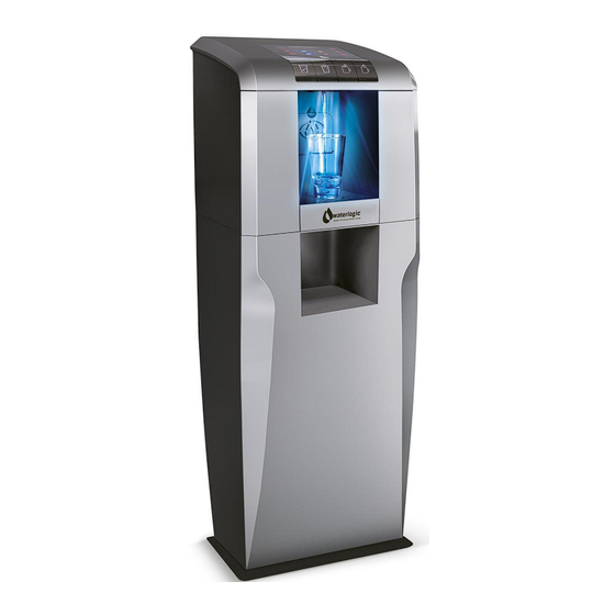
OPERATING INSTRUCTIONS Cold Sparkling Extra Hot The above picture shows front dispensing panel for the Waterlogic WL4FW. Button Operational Use Press the Cold Water selection button. There may be a 2 second delay as FIREWALL UV lamp purifies the water and the FIREWALL Sensor ensures your safety. - Page 11 Press the Extra Hot Water Selection button to elevate the hot tank to 95°C. Allow a few minutes for the temperature to rise in the hot tank. Press and hold both the Hot Water and the Extra Hot Water selection buttons simultaneously for 2 seconds and hot water will dispense.
- Page 12 DISPLAY PANELS AND ICONS UV Lamp Has Failed The UV Lamp is Sleep Mode - See troubleshooting operating press any section of manual button to bring machine out of sleep The Hot Tank is heating up A leak has been mode detected - See troubleshooting...
- Page 13 WL4FW CABINET ASSEMBLY WL4FW Manual Page 13– Revision: EU18-09-2020...
- Page 14 WL4FW Manual Page 14– Revision: EU18-09-2020...
- Page 15 WL4FW Manual Page 15– Revision: EU18-09-2020...
- Page 16 WL4FW Manual Page 16– Revision: EU18-09-2020...
- Page 17 WL4FW Manual Page 17– Revision: EU18-09-2020...
- Page 18 WL4FW Manual Page 18– Revision: EU18-09-2020...
-
Page 19: Reverse Osmosis Guide
REVERSE OSMOSIS QUICK GUIDE The WL4FW Water Treatment System contains a high capacity Reverse Osmosis Filtration System installed in the Base Cabinet. Efficiency is improved by utilizing the on-board booster pump to optimize the osmotic pressure, and an 18 Litre Bladder Tank is included in the Base Cabinet. The Filtration system has 4 Stages of Filtration with 450 Litre per day capacity combined with exclusive Firewall Purification. - Page 20 BASE CABINET SIDE REMOVAL WL4FW Manual Page 20– Revision: EU18-09-2020...
- Page 21 BASE CABINET CONFIGURATION FOR REVERSE OSMOSIS SYSTEMS WL4FW Manual Page 21– Revision: EU18-09-2020...
- Page 22 REVERSE OSMOSIS SETUP AND FILTER CHANGE INSTRUCTIONS 1. Remove Front Panel from Base Cabinet 2. Isolate Water Supply 3. Remove Pre-Carbon and Post-Carbon Filters and clear carbon fines by flushing 20 Litres of water through each filter individually to drain. 4.
- Page 23 LEFT SIDE INSIDE CABINET Left Side with Outside Panel Removed WL4FW Manual Page 23– Revision: EU18-09-2020...
- Page 24 RIGHT SIDE PANEL REMOVED WL4FW Manual Page 24– Revision: EU18-09-2020...
- Page 25 RO MEMBRANE INSTALLED REPLACING RO MEMBRANE Original Filter Configuration Part No Description RO-0001A Sediment Filter RO-0002A Pre-Carbon Block RO-0004C RO Membrane RO-0005A Post Carbon Black CT-2090-C 13W UV Lamp WL4FW Manual Page 25– Revision: EU18-09-2020...
-
Page 26: Installation Rail
ALWAYS USE INSTALL RAIL. It is required to use an installation rail for the installation of any Waterlogic Water Treatment System. Failure to use an installation rail can result in damage due to excessive pressures over a prolonged period of time and no additional leak protection. -
Page 27: Co2 Installation Procedure
INSTALLATION PROCEDURE The following instructions are for all models which have a sparkling water option IMPORTANT INFORMATION WARNING! Only competently trained people who fully understand the safety precautions associated with handling gas bottles should attempt to handle, connect or replace CO gas bottles. - Page 28 7. Check the new gas bottle is ‘food grade’ CO2 8. Remove the dust cap (where fitted) from the CO2 outlet on the bottle 9. Direct the outlet into a safe location, open the tap on the gas bottle for a second and close again, this will purge the gas which will clear any dust from the outlet 10.
-
Page 29: Wl4 Pcb Programming
WL4 PCB PROGRAMMING PROCEDURE The service PCB has been developed to allow the WL4 4 Firewall PCB to be reset using an external PCB. BUTTON DESCRIPTIONS UP: Menu Up DOWN: Menu Down ENTER: Enter and Modify SELECT: Select and Enter/Exit READ/SEND: Read/Send Data LED DISPLAY TEMP: Actual temperature and filter use hours... - Page 30 WL4FW Manual Page 30– Revision: EU18-09-2020...
- Page 31 WL4FW Manual Page 31– Revision: EU18-09-2020...
- Page 32 WL4FW Manual Page 32– Revision: EU18-09-2020...
- Page 33 WL4FW Manual Page 33– Revision: EU18-09-2020...
-
Page 34: Opening Top
OPENING TOP COVER Remove Two Screws 1. Remove screws from slide locks located near dispenser. Slide Locks Open 2. Push Slide Locks inward toward dispensing area. 3. Pull Cover forward and lift from the front to open Top Cover. 4. Locate Top Cover Support Arm attached to left side panel. -
Page 35: Pre-Delivery Procedure
• ¼” Plastic Tubing, at least 1 meter in length, and assorted ¼” quick connect fittings • TDS Meter and Test Strips for measuring chlorine – Optional • Sanitising Cartridge 1. Unpack the Waterlogic WL4FW and check exterior for damage. Sanitising Sanitise using Aquadosa or a 5.25% Sodium Hypochlorite solution or other approved cleaner throughout the cold and sparkling water circuits. - Page 36 4. Connect power to WL4FW Water Treatment System. Turn on Red Power Switch. DO NOT TURN ON GREEN HEATER/COMPRESSOR SWITCH AT THIS TIME. CAUTION! NEVER TURN ON HEATER BEFORE FILLING HOT TANK. Green Heater/Compressor Switch must be in the O=OFF position while the hot tank is empty.
- Page 37 CAUTION! NEVER TURN ON HEATER BEFORE FILLING HOT TANK. Green Heater/Compressor Switch must be in the O=OFF position while the hot tank is empty. Damage could occur within one minute and the overheat (high limit) will require manual reset if heater is turned on with an empty hot tank.
- Page 38 20. Connect supply water to the Water Bulkhead Fitting on back of cabinet. Turn on water supply and flush RO system to drain for 4 hours. Water should be draining from both Water Out line and the Drain Line. 21. After 4 hours of flushing, turn Off Incoming Water. Connect water line from the Base Cabinet to Water In fitting on WL4FW Water Treatment System.
- Page 39 30. Disconnect UV lamp to test UV lamp sensor operation. Unit should alarm and UV Icon on display will light. 31. Disconnect power to WL4FW Water Treatment System. 32. Reconnect UV lamp. 33. Connect power to WL4FW Water Treatment System. Compressor Test 34.
- Page 40 WL4FW DRAINING INSTRUCTIONS Draining Notes Drain the WL4FW Water Treatment System for transportation. WARNING! STORE UNIT EMPTY. ALWAYS SANITIZE BEFORE REUSE. The unit must be completely drained and sealed before storing to avoid stagnation and reduce microbial growth). Prior to draining the Hot Tank, turn Off the Green Compressor / Heater switch (O=OFF), and dispense 2 litres of hot water from the machine.
- Page 41 9. Disconnect Cold Line from top of Cold Tank. 10. Remove Drain Caps and Plug from Cold Water Tank Drain on the back of the WL4FW Water Treatment System. 11. Open Bladder Tank. 12. After unit has finished draining, replace Plug and Drain Caps. 13.
- Page 42 CAUTION! USE A WATER PRESSURE REGULATOR. Waterlogic will not be responsible for injury or damage caused by excessive water pressure. Operating pressure must be 2.7Bar to 4Bar (40 psi to 60 psi).
- Page 43 1. Unpack the Waterlogic WL4FW Water Treatment System and check exterior for damage. 2. Remove Front Panel from Base Cabinet opening Top of Panel and Removing Slide Bar. 3. Remove WL4FW Water Treatment System from packaging and place on top of base cabinet.
- Page 44 11. Connect supply water to water in fitting on back of cabinet. Turn on the Water Supply and flush RO system to drain for 4 hours. Water should be draining from both Water Out Line and Drain Lines. 12. After 4 hours, turn off Incoming Water. Connect Water Out Line from Base Cabinet to drain water in fitting on WL4FW Water Treatment System.
-
Page 45: Service Requirements
1. Visually inspect all electrical and water connections for signs of wear or damage. DANGER! HIGH VOLTAGE ELECTRICAL HAZARD. Unplug before inspection and service. 2. Waterlogic recommends changing the UV Lamp every 6 months. WARNING! ULTRAVIOLET RADIATION. Protect your skin and eyes against ultraviolet rays. - Page 46 HOT TANK DESCALING PROCEDURE The Hot Tank requires removal of mineral deposits (descaling) on a regular basis. Typically descaling should take place every 6 to 12 months to preserve the long-term health of your unit. Use non-toxic cleaner such as ScaleKleen, DEZCAL or 20% Citric Acid Solution to remove mineral deposits as directed by the manufacturer depending upon filtration and local water conditions.
- Page 47 6. Place a pitcher, catch basin or other container under the faucet of the WL4FW Water Treatment System. 7. Flush the Hot Tank until water runs clear. Ensure you pinch the hot water over flow tube to drain and clear the sub tank. 8.
-
Page 48: Hot Tank Principles
HOT TANK PRINCIPLES OF OPERATION All Waterlogic Hot Tanks have a built in Vent or Expansion Chamber in the top of the tank except for WL1000 (GF) units. The Vent Chamber allows for expansion of the water when it is heated. - Page 49 RESETTING THE HOT TANK OVERHEAT OR HIGH LIMIT SAFETY Turn off Green Heater/Compressor Switch on rear of unit. O=OFF Unplug the Power Cord from rear of unit. Remove Two Screws Slide Locks Open Remove the Tower Cover Locking Screws and Slide Locks towards outside of unit to unlock both locks.
-
Page 50: Wl4 Flow Diagrams
WL4 FLOW DIAGRAM Hot, Cold and Sparkling WL4FW Manual Page 49– Revision: EU18-09-2020... - Page 51 Hot and Cold WL4FW Manual Page 50– Revision: EU18-09-2020...
- Page 52 Cold and Sparkling WL4FW Manual Page 51– Revision: EU18-09-2020...
- Page 53 Cold Only WL4FW Manual Page 52– Revision: EU18-09-2020...
- Page 54 CARBONATION TANK FLOW DIAGRAM WL4FW Manual Page 53– Revision: EU18-09-2020...
- Page 55 REVERSE OSMOSIS FLOW DIAGRAM There is a 370 Liters per day (LPD) flow restrictor inline after the Main Unit bulkhead inlet fitting on all WL4FW Treatment Systems. Flow Restrictor Part Number AK-0014-B Check Valve WL4FW Manual Page 54– Revision: EU18-09-2020...
-
Page 56: Recommended Spares Holding
EL-5113R1 – Firewall UV Lamp Harness EL-5113 – Non-Firewall CAUTION! Use only Waterlogic Replacement parts that can be obtained from Waterlogic or an Authorized Waterlogic Dealer, failure to do so will void the Warranty. WL4FW Manual Page 55– Revision: EU18-09-2020... -
Page 57: Exploded Diagram With Spares
EXPLODED DIAGRAM WITH PARTS WL4FW Manual Page 56– Revision: EU18-09-2020... - Page 58 No. Part No. Description PL-1321 Top Cover Safety Support PL-1328 Mini Side Panel ST-8260 PCB Holder Bracket EN-6059 Plastic PCB Support EN-6117 Main PCB ST-8285 Main PCB Metal Cover EN-6119 LED PCB PL-1335 LED PCB Holder Sealing Rubber PL-1318 LED Hold Plate PL-1317 Top Cover Lock PL-1312-C...
- Page 59 ST-8267-B Drip Tray Sensor Pin - Right PL-1319-B Drip Tray Silver (BioCote®) - WL Logo CU-0055 Air Vent Clip PU-4064 Silicon Tube 5/16" PL-1354 Firewall Hot Water Faucet PL-1354-A Firewall Hot Water Faucet Insert Pipe ST-8261 Adaptor Holder Bracket EL-5128 Power adaptor 2A ST-8264-A Adaptor Fixing Bracket...
- Page 60 ST-8258 Mini Down Base PL-1311 Leak Detection Sensor Bracket ST-8207CN Leak Containment Tray Clip PL-1251CN Rubber Foot CT-2028 Drain Valve Cap CT-2039-A Drain Valve Body ST-8256 Front support Frame - Right CO-9041 Wire Condenser CO-9008 Filter Dryer ST-8255 Mini Front support Frame - Left PU-4022 Filter Head - Valved PU-4029...
- Page 61 CT-0016- Water Level Sensor L00-00 PU-4008 JG Equal Elbow Connector 1/4" CT-2037 Upper Safety Valve 1/4" for Sparkling Unit PU-4057 JG Non-Return Valve 1/4" CT-2073-A WL4 Firewall H2CP C&S Cold Tank PU-4140 JG End Stop 1/4" EL-5100 Brown Wire from Fuse Holder to Red S/W Including Fuse ST-8283 Electronics Cover Bracket EL-5113R1 –...
- Page 62 CT-2005 Fan Motor 230V/50-60Hz PL-1336 Upper Panel Wire Route Hole Silicon Cover ST-8259-D Upper Shelf & Back Panel HT-3036-A 1.2L 230V 500W Hot Tank PL-1330 Back Panel Hinge - A-4 PL-1331 Back Panel Hinge - A-1 EL-5016 Socket with EMI Filter EL-5004 Switch - Power (Red) EL-5005...
- Page 63 CT-2077-A Quartz Spiral Spacer to Outer Quartz Sleeve FU-0001-A Aluminium Housing ST-8298 System Fixing Bracket to the Upper Shelf PL-1337 LCD Cover Panel (WL Logo) Top Cover Silver with Firewall Logo - without buttons and LCD PL-1322-C cover PL-1323 4 Button Panel LP-7240 Sparkling Button Label LP-7237...
- Page 64 PL-1334 WL4 PCB Cover PL-1333 WL4 Back Panel Hinge - A-3 PL-1332 WL4 Back Panel Hinge - A-2 WL4FW Manual Page 63– Revision: EU18-09-2020...
- Page 65 WL4FW BASE LAYOUT WL4FW Manual Page 64– Revision: EU18-09-2020...
- Page 66 WL4FW BASE MAIN PARTS DRAWING AND PARTS LIST INCL REVERSE OSMOSIS WL4FW Manual Page 65– Revision: EU18-09-2020...
- Page 67 WL4FW BASE LAYOUT DRAWING AND PARTS LIST INCL REVERSE OSMOSIS Part No Description ST-8342 Fixing Bracket – Base Cabinet Back Panel JG Bulkhead Connector Union 1/4" * PU-4028 1/4"(PI1208S) B2.1 AK-0014-B 1.8mm Flow Restrictor ST-8273 Base Cabinet Back Panel ST-8270 Base Cabinet Support Frame PL-1339 Base Cabinet Plastic Side Panel-L...
- Page 68 PU-4024 3” Filter Clip RO-0001-A Sediment Filter – Micro PU-4008 JG Equal Elbow Connector 1/4" (PI0308S) RO-0003-A RO Housing Micro RO Membrane 100 GPD – Micro Filter RO-0006-A 1/4" Rigid Elbow for RO Housing Micro RO-0005-A Post Carbon Filter – Micro HG Shut Off Valve NPT 5/16”...
-
Page 69: Electrical Schematic Diagram
WL4FW ELECTRICAL SCHEMATIC DIAGRAM DANGER! HIGH VOLTAGE ELECTRICAL HAZARD. PCB (Printed Circuit Board) contains High Voltage. Only trained and qualified technicians should attempt live testing. WL4FW Manual Page 68– Revision: EU18-09-2020... - Page 70 WL4FW Manual Page 69– Revision: EU18-09-2020...
- Page 71 WL4FW Manual Page 70– Revision: EU18-09-2020...
- Page 72 WL4FW Manual Page 71– Revision: EU18-09-2020...
- Page 73 FAULT CODE TROUBLESHOOTING INDEX There are two leak detector sensors in the WL4FW Water Treatment Systems. Possible Reason Solution Check for water in base cabinet by opening and removing Leak Sensor located inside the front cover. If water is found in leak tray, dry out leak tray. base cabinet on the right side.
- Page 74 Possible Reason Solution Replace filter. See parts section for part number. Which filter Filter needs replacing depends on water quality being served to the machine. Possible Reason Solution Empty drip tray and clean before re installing to the machine. Full Drip Tray Ensure the leak detection probes in the drip tray are dry.
-
Page 75: Cold Water Troubleshooting
Wait for cold tank to chill water to temperature prior to dispensing more cold water. Tank has run out of cold water. A greater capacity of Waterlogic Water System is available. Check continuity of thermostat with multimeter. Replace Cold Water Thermostat thermostat as required. -
Page 76: Hot Water Troubleshooting
HOT WATER TROUBLESHOOTING INDEX Hot Water is not Hot (87° +/- 5°C) The Hot temperature set point is 87°C and is controlled by a thermostat on the side of the tank. There are two resettable overheat or high limit safety above the thermostat on the side of the tank that will trip to prevent damage to the unit if the tank is dry heated (turned on without water in it). -
Page 77: Power Troubleshooting
POWER TROUBLESHOOTING INDEX 1. Red Power Switch, Green Heater and Compressor Switch and the LEDs on the Front won't light 2. Red Power Switch, Green Heater and Compressor Switch are lit but the red LED on the Front is not lit 3. - Page 78 Red Power Switch, Green Heater and Compressor Switch are lit but the red LED on the Front is not lit Possible Reason Solution Bad Transformer Replace Transformer Black Power Connector to the Properly connect. PCB is not properly connected Bad Front PCB Replace Front PCB Defective Red Power Switch Replace Red Power Switch...
- Page 79 Compressor is Not Running Possible Reason Solution Turn Green Heater and Compressor Switch on. Green Heater and Compressor I = ON Switch button on unit is in the off position Turn Green Heater and Compressor Switch off. O = OFF. Remove the compressor cap on side of the compressor;...
- Page 80 DISPENSING TROUBLESHOOTING INDEX 1. Irregular / Intermittent Dispensing 2. Steady Drip out of Faucet 3. Hot Water or Steam coming out of both the Faucet and the Vent Hole 4. Hot Water coming out of Faucet Vent Hole 5. Restricted Flow of Hot Water 6.
- Page 81 Irregular / Intermittent Dispensing Possible Reason Solution Check water pressure at the inlet bulkhead with a water pressure gauge. Too much water pressure. Additional method of verification is to turn off water to unit Recommend 2.7 – 4Bar for and press the dispense button. Does the solenoid open WL4FW Water Treatment without water pressure to the unit? Listen for solenoid to System to operate properly.
- Page 82 Steady Drip Out of Faucet Possible Reason Solution Debris in Solenoid Inspect Solenoid for debris and clean out as needed. Hot Water or Steam Coming out of both the Faucet and Vent Hole Possible Reason Solution Improper tubing attachment Check that the tubing is connected from tank outlets to correct from the hot tank to faucet or faucet attachments.
- Page 83 Restricted Flow of Hot Water Possible Reason Solution Partially closed water supply valve to Open water supply valve. the unit. Hot Tank outlet hole is scaled over. Descale Tank. Tubing is creased or has a “kink” in it. Inspect and replace tubing as necessary. Faucet nipple screen mesh has Unscrew faucet nipple from faucet and remove any obstruction(s)
- Page 84 Small Outlet Vent Hole susceptible to scale Descale Tank. build up. All Waterlogic Hot Tanks have a built-in Vent or Expansion Chamber in the top of the tank except for WL1000 (GF) units. The Vent Chamber allows for expansion of the water when it is heated.
- Page 85 Dispenses Hot and Cold Water at the Same Time Possible Reason Solution Remove Top cover. Check Hot Solenoid: Dispense cold water and visually inspect tubing for water flow from both tanks. Hot or Cold solenoid is stuck open. Check Cold Solenoid: Disconnect elbow from outlet of cold solenoid. Select hot water and dispense (quickly releasing dispensing button to avoid much water coming out of cold solenoid.
- Page 86 Water does not dispense from Unit Possible Reason Solution Closed water supply valve Open the water supply valve. The unit is not properly Check electrical outlet connection, or for blown circuit breaker. plugged into electrical outlet Green Heater and Compressor Turn Green Heater / Compressor Switch on.
- Page 87 Cold Water Dispenses from Faucet and Vent Outlet Simultaneously Possible Reason Solution Improper tubing attachment Verify tubing is connected properly from tank outlets to correct from the tank to faucet or vice faucet attachments. versa Scale has formed inside cold Remove cold water outlet tube from tank to faucet.
- Page 88 Run On exists because the tanks pressurize as water is being dispensed. Every Waterlogic tank has an outlet restrictor to ensure the tanks remain full of water and water is controlled as it is released to the faucet.
Need help?
Do you have a question about the WL4FW FIREWALL and is the answer not in the manual?
Questions and answers