Table of Contents
Advertisement
Quick Links
Advertisement
Table of Contents

Related Manuals for Powermatic OES9138B


Summary of Contents for Powermatic OES9138B
- Page 1 Operating Instructions and Parts Manual Oscillating Edge Sander Models OES9138B and OES9138B-3 POWERMATIC 427 New Sanford Road La Vergne, TN 37086 Part No. M-PM1-263 Ph.: 800-274-6848 Edition 2 04/2024 www.powermatic.com Copyright © 2024 Powermatic...
-
Page 2: Warranty And Service
Powermatic sells through distributors only. The specifications listed in Powermatic printed materials and on the official Powermatic website are given as general information and are not binding. Powermatic reserves the right to effect at any time, without prior notice, those alterations to parts, fittings, and accessory equipment which they may deem necessary for any reason whatsoever. -
Page 3: Table Of Contents
2.0 Table of Contents Section Page 1.0 Warranty and Service ............................. 2 2.0 Table of Contents ............................3 3.0 Safety Warnings ............................. 4 4.0 About this Manual ............................5 5.0 Specifications ..............................6 6.0 Features ................................. 7 7.0 Setup and Assembly ............................8 7.1 Shipping Contents ............................ -
Page 4: Safety Warnings
“horse- intended use. If used for other purposes, play” are careless acts that can result in serious Powermatic disclaims any real or implied injury. warranty and holds itself harmless from any 21. Maintain a balanced stance at all times so that injury that may result from that use. -
Page 5: About This Manual
If there are questions or comments, please contact your local supplier or Powermatic. Powermatic can also be reached at our web site: www.powermatic.com. -
Page 6: Specifications
Weight, Shipping/Net (lbs.) ..........810/660 ............. 810/660 The above specifications were current at the time this manual was published, but because of our policy of continuous improvement, Powermatic reserves the right to change specifications at any time and without prior notice, without incurring obligations. -
Page 7: Features
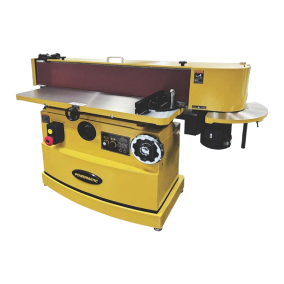
6.0 Features Figure 6-1... -
Page 8: Setup And Assembly
1100 CFM. 1. Lift the machine from the shipping skid with a Powermatic has a full line of dust collection systems hoist or forklift by attaching straps to the available. See your dealer or visit our website at eyebolts on top the sander. -
Page 9: Electrical Connections
8.0 Electrical Connections Make sure the voltage of your power supply matches the specifications on the motor plate of the machine. Electrical connections must be made by a qualified electrician in compliance with all relevant codes. This machine must be properly grounded to help prevent electrical shock and possible fatal injury. -
Page 10: Adjustments
Table 1 9.0 Adjustments Remove the safety key (A, Figure 9-1) from the power switch to guard against accidental startup while making adjustments. For safety key information, see Section 10.3. 9.1 Control and Adjustment Identification Refer to Figures 9-1 and 9-2. Figure 9-2: Control Panel Sanding Machine Controls 9.2 Adjusting Sanding Drum Tilt... -
Page 11: Main Table Positioning
Moving Table Up and Down 7. Turn sanding belt tilt wheel counterclockwise until it stops. Turn table height wheel (D) clockwise to raise the 8. Set your adjustable square to 135° and place it table. Turn table height wheel counterclockwise to on the table and against front of sanding belt lower the table. -
Page 12: End Guard
9.5 End Guard Refer to Figure 9-9. The end guard (A) on the right side of the machine can be swung out of the way for sanding long workpieces and for contour sanding using the end table (D). NOTE: The miter gauge will need to be removed for sanding long workpieces. -
Page 13: Replacing Sanding Belt
9.7 Replacing Sanding Belt Refer to Figures 9-11, 9-12, and 9-13. 1. Disconnect machine from power source. 2. Swing the end guard (A, Figure 9-9) out of the way (see Section 9.5). Open the belt guard (B). 3. Release tension on the belt by pulling the tension lever (C) all the way up until it stops against the screw head. -
Page 14: Operation
10.0 Operation To Stop — Press the STOP button (B). Reset — If the sander stops without pressing the Your oscillating belt edge sander is designed and STOP button, as the result of a tripped fuse or circuit manufactured for long-term operation creating breaker: superior sanded surfaces for wood products. -
Page 15: Maintenance
11.1 Lubrication 11.0 Maintenance All ball bearings are sealed for life and do not require further lubrication. Always disconnect power to Periodically apply grease to the trunnion teeth for the machine and remove the safety key before smooth operation of the belt angle worm gear performing maintenance. -
Page 16: Troubleshooting
12.0 Troubleshooting Trouble Probable Cause Remedy Machine will not Machine not connected to Verify machine is connected to power. start/restart or power source. repeatedly trips Fuse blown, or circuit Replace fuse or reset circuit breaker. circuit breakers or breaker tripped. blows fuses. - Page 17 Trouble Probable Cause Remedy Sanding belt won’t Excessive bite, or feed Allow sanding belt to cut freely, do not force. come up to speed. pressure too great. Belt won’t track. Drum is worn. Replace drum. Belt is stretched unevenly. Replace belt. Belt slips or stalls Sanding belt tension not Make sure lever is down all the way.
-
Page 18: Replacement Parts
Non-proprietary parts, such as fasteners, can be found at local hardware stores, or may be ordered from Powermatic. Some parts are shown for reference only and may not be available individually. -
Page 19: Base Assembly - Exploded View
13.1.1 Base Assembly – Exploded View... -
Page 20: Base Assembly - Parts List
1 ....OES9138B-501 ..Eyebolt ..............M10 x 1.5P x 20L ..2 2 ....OES9138B-502 ..Lock Knob ...................... 2 5 ....OES9138B-505K ..Top Cover Assembly (incl. belt tracking label) ..........1 7 ....OES9138B-507 ..Rubber Pad ....................5 8 .... - Page 21 81.8 ... OES9138B-581-8 ..Contactor ..............230V / 60Hz ....1 81.9 ... OES9138B-549 ..Phillips Pan Head Machined Screw ......M4 x 0.7P x 6L ....2 81.10 ..OES9138B-581-10K . Power Cable Assembly (for Single Phase) ....SJT 12AWGx3Cx2300mm ... 1 ....
-
Page 22: Tracking And Belt Release Assembly - Exploded View
13.2.1 Tracking and Belt Release Assembly – Exploded View... -
Page 23: Tracking And Belt Release Assembly - Parts List
19 ....TS-1502021 ....Socket Head Cap Screw ......... M5x0.8Px10L, Grd 12.9 ..2 20 ....OES9138B-420 ..Compression Spring Assembly ..............1 23 ....OES9138B-423 ..Flat Washer ............. 8.2 x 30 x 4.0T ....2 24 ....OES9138B-424K ..Spherical Bearing Assembly ........SBPFL 203 ....1 32 .... - Page 24 13.3.1 Table Assembly – Exploded View...
- Page 25 11 ....OES9138B-311 ..O-Ring ..............P30 ....... 2 12 ....OES9138B-312 ..Socket Head Cap Screw w/threadlocker ....M10 x 1.5P x 30L ..2 13 ....Part Not Offered ..Lock Washer ............M10, Grade 4.6 ..... 6 14 ....
-
Page 26: Drive Assembly - Exploded View
43 ....TS-1521011 ....Set Screw ..............M4x0.7Px4L, Grd 12.9 ..1 ....OES9138B-344 ..Table Caution Label (not shown) ..............1 ....OES9138B-345 ..Table Horizontal Movement label (not shown) ..........1 13.4.1 Drive Assembly – Exploded View 13.4.2 Drive Assembly –... -
Page 27: Contour Sanding Assembly - Exploded View
13.5.1 Contour Sanding Assembly – Exploded View 13.5.2 Contour Sanding Assembly – Parts List Index No Part No Description Size 1 ....OES9138B-207K ..Side Table Assembly ..................1 5 ....OES9138B-201K ..Side Table Bracket Assembly ................ 1... -
Page 28: Electrical Connections
14.0 Electrical Connections 14.1 1 Phase, 230V... -
Page 29: Phase, 230V
14.2 3 Phase, 230V... - Page 30 NOTES...
- Page 31 NOTES...
- Page 32 427 New Sanford Road LaVergne, Tennessee 37086 Phone: 800-274-6848 www.powermatic.com...
Need help?
Do you have a question about the OES9138B and is the answer not in the manual?
Questions and answers