Table of Contents
Advertisement
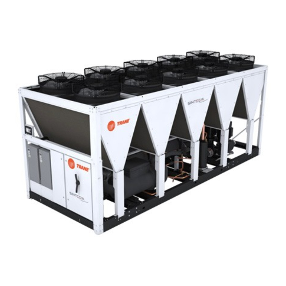
RTAF SE/HE/XE/HSS/HSE/XSE/XSS
R134a, R513A, R1234ze
Air-cooled
Helical-rotary chillers
300 - 1900 kW
July 2020
RLC-SVX19J_SHORT-GB
Confi dential and proprietary Trane information
Original instructions
Sintesis chillers are part of the Trane Technologies EcoWise™
portfolio of products that are designed to lower their
environmental impact with next-generation, low global warming
potential (GWP) refrigerants and high effi ciency operation.
Advertisement
Table of Contents

Related Manuals for Trane Sintesis RTAF SE


Summary of Contents for Trane Sintesis RTAF SE
- Page 1 Air-cooled Helical-rotary chillers 300 - 1900 kW Sintesis chillers are part of the Trane Technologies EcoWise™ portfolio of products that are designed to lower their environmental impact with next-generation, low global warming potential (GWP) refrigerants and high effi ciency operation.
-
Page 2: Warranty
Trane, to VALIDATE this WARRANTY. Contractor To avoid death, injury, equipment or property damage, the must provide a two-week startup notifi cation to Trane (or an following recommendations should be observed during agent of Trane specifi cally authorized to perform startup). -
Page 3: Pre-Installation
Request an immediate, joint inspection of the damage with the carrier and the consignee. • Notify the Trane sales representative and arrange for repair. Do not repair the unit, however, until damage is inspected by the transportation representative. - Page 4 (a) Start-up must be performed by Trane or an agent of Trane specifi cally authorized to perform start-up and warranty of Trane® products. Contractor shall provide Trane (or an agent of Trane specifi cally authorized to perform start-up) with notice of the scheduled start-up at least two weeks prior to the scheduled start-up.
-
Page 5: Unit Model Number Description
Unit Model Number Description Digit 1, 2, 3, 4 – Unit model Digit 12 - Effi ciency RTAF = Air-Cooled Chiller N = Standard Effi ciency H = High Effi ciency Digit 5 to 7 - Nominal Tonnage A = Extra Effi ciency 090 = 90 tons U = High Seasonal Short (HSS) 100 = 100 tons... - Page 6 Unit Model Number Description Digit 25 - Free Cooling Digit 39 – Open for future use = X X = No Free Cooling Digit 40 – Power socket F = Total Free-Cooling Direct X = None G = Partial Free-cooling Direct P = Included (230V - 100W) H = Total Free Cooling Glycol Free J = Partial Free Cooling Glycol Free...
-
Page 7: Installation Requirements
10 Bar at 10°C), call a qualifi ed service organization schematics provided in the control panel. and the appropriate Trane sales offi ce. Install heat tape and insulate the chilled water lines and any other portion of the system, as required, to... - Page 8 2. For installations with obstructions or multiple units, are included in submittals and diagrams provided in refer to Trane offi ce for Close Spacing and Restricted documentation package. Airfl ow advices.
- Page 9 Installation Requirements Elastomeric Isolators Installation Isolator Pads Installation (Optional) (Optional) Isolators are ready to install. Mountings have to be placed on a rigid and level foundation. External Isolators are ready to install. Mountings have to equipment should not transmit additional vibration to be placed on a rigid and level foundation.
-
Page 10: Chilled Water Piping Recommendations
Neither salt nor brackish water is recommended for use from the chilled water system. Install necessary pressure in Trane air-cooled chillers. Use of either will lead to an gauges to monitor the entering and leaving chilled water unpredictably shorter life cycle. Trane encourages the pressure. -
Page 11: Evaporator Piping Components
Evaporator Piping Evaporator Piping Components Piping components include all devices and controls used to provide proper water system operation and unit operating safety. A typical RTAF evaporator piping is shown below. Figure 3 – Typical RTAF evaporator water piping 1 = Isolation valve Pi = Pressure gauge 2 = Vibration isolators FT = Water Flow Switch... - Page 12 Drainage A large capacity drain must be provided for water vessel drain-down during shutdown or repair. The evaporator is provided with drain connections. An air vent on top of the evaporator waterbox prevents vacuum by removing air from evaporator for complete drainage. Drain connections and vents are also provided on header pipes for use when free-cooling option.
-
Page 13: Evaporator Flow Switch
Incomplete drainage increases the risk of damage due time delay after a “loss-of-fl ow” diagnostic before to expansion associated with trapped water freezing. shutting the unit down. Contact a Trane service representative if nuisance machine shutdowns Note: If evaporator will be drained for winter storage, the persist. -
Page 14: Optional Integrated Pump Package
Optional Integrated Pump Package Installation – Mechanical Chiller can be ordered with an optional integrated hydraulic module. In this case, chiller will be provided with the following components factory mounted and tested: • Twin centrifugal water pump, Low pressure or High pressure (option) •... -
Page 15: Total Heat Recovery
Total Heat Recovery 2 versions: - Digit 23=T Full equipment (BPHE + Water lines + 3-ways water valve + heaters + fl ow-switch + insulation) - Digit 23=V Naked (BPHE + insulation) - This type of unit remains an air-cooled chiller before modifi cation into a Total Heat Recovery unit. Start up and Shut down are always carried out in chiller mode. -
Page 16: Optional Free-Cooling
Optional Free-Cooling Chiller integrated free-cooling General information operation mode The chiller integrated free-cooling system fl uid based consist in a set of “Macro-channels” or “Radiators” coils, The power of chiller integrated free-cooling relies on fi t in the same frame than the MCHE condenser coils the chiller control to maximize the use of free-cooling of the chiller refrigerant circuit. - Page 17 Optional Free-Cooling Figure 8 – Flow chart – Free-Cooling – Direct free cooling version Note: glycol free cooling chilled water setpoint should be in the range of [4°C - 20° C]. Water & Glycol mixture is fi lled on the free cooling coils on valve item 4 (3/4”). RLC-SVX19J_SHORT-GB...
- Page 18 Free Cooling, Direct free cooling version b.Partial Free Cooling, Direct free cooling version If there is a need to get a defi nition for partial heat recovery coil distribution, please contact the Trane Sales offi ce. In order to maximize tandem operation of free cooling...
- Page 19 Optional Free-Cooling Figure 11 – Flow chart - Free cooling - Glycol free version Note: glycol free cooling chilled water setpoint should be in the range of [4°C - 20° C]. Glycol is fi lled on the free cooling coils on valve item 4 (3/4”). Note for installation All Submittal, lifting diagram, neoprene pads positioning and wiring diagrams have been supplied with chiller order.
- Page 20 Optional Free-Cooling The free cooling option circuit consists of copper, metal system. carbon steel, cast iron, zinc, synthetic rubber, brass, and The building glycol loop should not be vented to Aluminum AA3102, AA3003, AA4045 in addition to other atmosphere. A closed system is required to limit materials that may be in the building loop connected oxidation potential within the loop.
- Page 21 Optional Free-Cooling With a Phillips screwdriver, move the end of travel. Fix it to always keep an opening between 100% and the minimum desired (50%) in example below. If the minimum opening is modifi ed after the fi rst powering, motor re-calibration is needed to validate the new operating range.
-
Page 22: Evaporator Waterside
Evaporator Waterside Freeze Protection Depending on the ambient temperature the unit may be 2. Freeze inhibitor exposed to freeze, there are multiple options for freeze protection. They are listed in order of highest ambient a. Freeze protection can be accomplished by adding (least freeze protection) to the lowest ambient (most suffi... -
Page 23: General Electrical Recommendations
WARNING! • For variable frequency drives or other energy storing The Warning Label is displayed on the equipment components provided by Trane or others, refer to the and shown on wiring diagrams and schematics. Strict appropriate manufacturer’s literature for allowable adherence to these warnings must be observed. -
Page 24: Electrical Data
General Electrical Recommendations Electrical data To get the following electrical data details: Refer to General Data tables for each unit confi guration and size. - Maximum Power input (kW) - Unit rated amps (Max compr +Fan+Control) - Unit start up amps (Starting Amps of the largest compr+RLA of 2nd compr+RLA of all fans+ control) - Compressor Power factor - Disconnect switch size (A) - Short Circuit Rating for all sizes =35 kA... -
Page 25: Installer-Supplied Components
Tracer UC800 activates the pumps. If ambient supplied devices temperatures below -20°C are expected, contact your • Fused-disconnect switches Trane local offi ce. Power Supply Wiring CAUTION! The control panel main processor does not check for loss of power to the heat tape nor does All power supply wiring must be sized and selected it verify thermostat operation. -
Page 26: Alarm And Status Relay Outputs (Programmable Relays)
Installer-Supplied Components Alarm and Status Relay Outputs (Programmable Relays) See RTAF User Guide for alarm and status relay outputs. EDLS and ECWS Analog Input Signal Wiring Details See RTAF User Guide for EDLS and ECWS. RLC-SVX19J_SHORT-GB... -
Page 27: Operating Principles
Operating Principles This section describes the overall fl ow chart principle for RTAF . Detailed information for a given order is supplied with order package documentation. Figure 12 – Example of Typical Refrigerant System Schematic & Oil Lube Circuit Schematic 1 = Screw compressor PT = Pressure transducer 2 = Evaporator... -
Page 28: Refrigerant Circuit
1. Refrigerant and Oil RTAF use R134a, R513A or R1234ze, Trane believes that responsible refrigerant practices are important to the environment, our customers, and the air conditioning industry. All technicians who handle refrigerants must be properly qualifi... -
Page 29: Compressor And Lube Oil System
Operating Principles Compressor and Lube Oil System The rotary screw compressor is semi-hermetic, direct drive, with rolling element bearings, differential refrigerant pressure oil pump and oil heater. The motor is a suction gas cooled, hermetically sealed, two-pole squirrel cage induction motor. Capacity control is done via a slide valve on fi... -
Page 30: Controls Overview
However to adequately service Sintesis RTAF chillers, Tracer™ TU service tool is required (Non-Trane personnel, contact your local Trane offi ce for software purchase information). Tracer TU adds a level of sophistication that improves service technician effectiveness and minimizes chiller downtime. -
Page 31: Operating Map
- It is not possible to have a unit operating low and high ambient. For specifi c application with wide ambient contact Trane sales offi ce. - For RTAF 250 to 450 with a single pass evaporator, Leaving Water Temperature cannot exceed 18.3°C. -
Page 32: Pre-Start Checkout
Pre-Start Checkout Installation Checklist Unit Voltage Power Supply Complete this checklist as the unit is installed, and verify Unit voltage must meet the criteria given in the that all recommended procedures are accomplished installation Electrical Section. Measure each lead of before the unit is started. -
Page 33: Water System Flow Rates
Pre-Start Checkout WARNING! It is imperative that L1, L2, and L3 in the Figure 15 – Pump Package starter be connected in the A-BC phase sequence to prevent equipment damage due to reverse rotation. WARNING!To prevent injury or death due to electrocution, take extreme care when performing service procedures with electrical power energized. - Page 34 Pre-Start Checkout Tracer UC800 Set-Up Using Tracer TU service tool, adjust the settings. Refer to Tracer TU manual and UC800 user guide for instruction on settings. CAUTION! To prevent compressor damage, do not operate the unit until all refrigerant valves and oil-line service valves are opened.
-
Page 35: Unit Start Up Procedures
Unit Start Up Procedures Daily Unit Start Up 4. Clean the air fi lter located on the door of the control panel of AFD only on following unit type: The timeline for the sequence of operation begins with a - RTAF HSE sizes 155 and 175 on circuit 1 power-up of the main power to the chiller. -
Page 36: Temporary Shutdown And Restart
Unit Start Up Procedures CAUTION! To prevent damage to the compressor, ensure Extended Shutdown Procedure that all refrigerant valves are open before starting the The following procedure is to be followed if the system unit. Do not use untreated or improperly treated water. is to be taken out of service for an extended period of Equipment damage may occur. -
Page 37: Periodic Maintenance
Stay aware of unit enhancements, conversion refrigerants, compatible parts, and manufacturer’s Have Trane or another qualifi ed laboratory perform recommendations that will reduce refrigerant a compressor oil analysis to determine system emissions and increase equipment operating moisture content and acid level. - Page 38 Periodic Maintenance • Possible low discharge superheat at high loads ensure a 2 circuit fully loaded chiller then he must lockout one circuit and perform charge optimization for • High condenser + Subcooler pressure drop 1 circuit at a time Some of the symptoms of a refrigerant over-charged unit •...
-
Page 39: Low Side Charge-Isolation Procedure
The oil quantity is written on the nameplate of the unit. Inspect the replacement fi lter element and lubricate the o-ring with Trane oil advised for the unit (see general data table). Install the new fi lter element in the fi lter housing. - Page 40 7/16 o-ring boss plug normally in this location will have to be replaced by a 7/16-schraeder fi tting (Trane part number VAL07306). If this part is not available quickly, schraeder fi tting 2 or 1 = Oil separator 3 (Figure 18) could be removed and put in location 1.
-
Page 41: Field Oil-Charging Procedure
Figure 19: GP4 Compressor CAUTION! Use only Trane Oil 00048E in RTAF SE HE and XE chillers and Trane OIL 00317 for HSE version in the RTAF units to avoid any catastrophic damage to the compressor or unit. Deduct from fi nal charge, all charge added for prelubrifi... - Page 42 Periodic Maintenance to be isolated and pulled into vacuum. Note: Ensure that the compressor is not pressurized. Open the fl are fi tting on the oil-line shutoff valve. Open the fl are fi tting on the fi lter housing. This is the port that must be used to put oil into the compressor.
-
Page 43: Condenser Coils Mche Maintenance
If the leak is found to be within the tube area of the coil, a fi eld repair kit (KIT16112) is available through your local Trane parts center. Because of the all-aluminum construction and aluminum’s high thermal expansion rate, a leak located at or on the header assembly cannot be repaired. -
Page 44: Water Pump Maintenance
Integrated Pump Maintenance (Optional with Pump Package) Water Pump Maintenance CAUTION! The lifting eyebolts of the motor are suitable for the weight of the motor only. It is not allowed to carry the complete pump on the lifting eyebolts of the motor. Motor Check the motor at regular intervals. -
Page 45: Log Check Sheet
Log Check Sheet The operator log sheet are included for use as appropriate, for installation completion verifi cation before Trane Start-up is scheduled, and for reference during the Trane Start-up. Operator Log Sintesis RTAF chiller with UC800 Controller - Tracer AdaptiView Reports - Log Sheet... -
Page 46: Recommended Service Routine Frequencies
As a commitment to our customers, we have created a wide service network staffed with experienced factory- authorized technicians. At Trane we offer all the benefi ts of after sales service direct from the manufacturer and we are committed to our mission statement to provide effi cient customer care. -
Page 47: Additional Services
Additional services Oil analysis Annual cooling tower maintenance Trane Oil Analysis is a predictive tool used to detect This Service includes the inspection and maintenance of minor issues before they become major problems. It also the cooling tower at least once a year. - Page 48 For more information, please visit trane.com or tranetechnologies.com. Trane has a policy of continuous product and product data improvement and reserves the right to change design and specifi cations without notice. We are committed to using environmentally conscious print practices.
Need help?
Do you have a question about the Sintesis RTAF SE and is the answer not in the manual?
Questions and answers