Only qualified personnel should install and service the equipment. The installation, starting up, and servicing of heating, ventilating, and air-conditioning equipment
can be hazardous and requires specific knowledge and training. Improperly installed, adjusted or altered equipment by an unqualified person could result in death or
serious injury. When working on the equipment, observe all precautions in the literature and on the tags, stickers, and labels that are attached to the equipment.
Gear-driven centrifugal
water-cooled liquid
chillers with
adaptiview controls (128 pages)
Summary of Contents for Trane S Series
Page 1
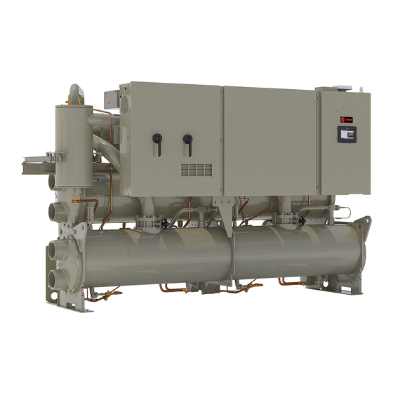
Installation, Operation, and Maintenance Series R® Rotary Liquid Chillers Water-Cooled Model RTWD 60 to 250 Tons X3964145002 SAFETY WARNING Only qualified personnel should install and service the equipment. The installation, starting up, and servicing of heating, ventilating, and air-conditioning equipment can be hazardous and requires specific knowledge and training.
This document and the information in it are the property of Trane, and may not be used or reproduced in whole or in For installation only in locations not accessible to the part without written permission. Trane reserves the right to general public.
Model Number Information Nameplates • Compressor electrical characteristics • Utilization range Unit nameplates are applied to the exterior of the control panel. A compressor nameplate is located on each • Recommended refrigerant compressor. When the unit arrives, compare all nameplate See Model Number Descriptions chapter for compressor data with ordering, submittal, and shipping information.
Model Number Descriptions Unit Model Number Digit 1, 2, 3, 4 — Chiller Model Digit 15 — Unit Application Digit 26 — Power Line Connection Type RTWD = Water-Cooled Chiller Series R® A = Std Condenser <=95°F/35°C Entering Water A = Terminal Block Temperature D = Circuit Breaker B = High Temperature Condenser >95°F/35°C...
Page 7
Model Number Descriptions Digit 36 — Power Meter Digit 45 — Factory Charge Digit 59 — Performance Test 0 = No Power Meter 5 = Full Factory Refrigerant Charge (R-513A) 0 = No Performance Test E = Energy Meter 6 = Nitrogen Charge (R-513A Field Supplied) C = 1–Point Test with Report 7 = Full Factory Refrigerant Charge (R-515B) D = 2–Point Test with Report...
The RTWD series features Trane's exclusive Adaptive are placed inside the control panel and/or starter panel for Control logic with chiller controls. It monitors the control shipment.
Page 10
General Information Table 1. General data – RTWD, 60 Hz, standard efficiency (continued) Size Water Conn. Size 12.4 14.2 16.0 16.9 18.5 18.5 20.9 Water Storage 46.8 53.6 60.4 63.8 70.1 70.1 79.2 Minimum Flow Maximum Flow 18.9 22.7 26.5 28.4 31.0 31.0...
Page 11
General Information Table 2. General data – RTWD, 60 Hz, 80 to 130 tons, high efficiency (continued) Size Maximum Flow 11.0 14.1 15.3 17.2 18.8 20.0 Condenser Water Conn. Size Non-ASME Victaulic Water Conn. Size ASME Flange 90.0 90.0 90.0 90.0 90.0 90.0...
Page 12
General Information Table 3. General data – RTWD, 60 Hz, 150 to 250 tons, high efficiency (continued) Size Water Conn. Size 18.8 20.0 22.0 23.8 27.9 31.0 Water Storage 71.2 75.6 83.2 90.1 105.5 117.5 Minimum Flow 10.0 Maximum Flow 21.6 23.3 26.1...
Page 13
General Information Table 4. General data – RTWD, 60 Hz, premium efficiency Size Compressor L2/M1 M1/M1 M1/M2 M2/M2 Size Ckt1/Ckt2 (L2/M3) (M3/M3) (M3/M4) (M4/M4) Evaporator 2 Pass Arrangement Water Conn. Size 27.8 27.8 29.3 31.3 Water Storage 105.1 105.1 110.9 118.3 Minimum Flow 11.0...
Page 14
General Information Table 4. General data – RTWD, 60 Hz, premium efficiency (continued) Size 9.5/11.4 11.4/11.4 11.4/11.4 11.4/11.4 Oil Charge_R-515B 9.0/10.8 10.8/10.8 10.8/10.8 10.8/10.8 Note: Data containing information on two circuits is shown as circuit 1/circuit 2. RLC-SVX09Q-EN...
• Notify the carrier's terminal of the damage immediately, Note: Unit Start-up must be completed by a qualified Trane by phone and by mail. Request an immediate, joint service technician. Table 5. Installation requirements...
Page 16
Pre-Installation Table 5. Installation requirements (continued) Type of Requirement Trane Supplied Field Supplied Field Installed Trane Installed Field Installed Electrical • Circuit breakers • Circuit breakers • Unit mounted starter • Electrical connections to unit mounted starter (optional) • Electrical connections to remote mounted starter (optional) •...
Page 20
Unit Dimensions and Weights Table 7. RTWD, 150 to 250 tons, 60 Hz – in (mm) RTWD High Efficiency Prem Efficiency 220, 250T 150-200T 150-200T A (2 pass evap) 132.3 (3360) 136.1 (3456) 147.9 (3755) B (3 pass evap) 132.8 (3371) 136.1 (3456) 150.9 (3831) 75.6 (1920)
Page 21
Unit Dimensions and Weights Figure 3. RTWD unit footprint Table 8. RTWD unit footprint High Efficiency High Efficiency Premium Efficiency 150- Standard Efficiency 80 - 130T (60Hz) 150 - 250T (60Hz), 200T (60Hz) Dimension inch inch inch inch 3.68 93.5 3.68 93.5 3.68...
Unit Dimensions and Weights Service Clearance Figure 4. RTWD service clearances Notes: • See table below for clearance values. • All unit configurations require 36 inch (914 mm) clearance above the unit. • All clearance values are taken from the edge of the unit.
Page 23
Unit Dimensions and Weights Table 10. Weights – RTWD, 60 Hz (continued) Standard Efficiency High Efficiency Premium Efficiency rating Operating Shipping Operating Shipping Operating Shipping Model 6530 2962 6248 2834 6510 2953 6230 2826 6535 2964 6244 2832 6543 2968 6248 2834 6971...
“Unit Dimensions,” p. 17 for unit operating weights. Once in place, the unit must be level within 1/4 inch (6.4 mm) over its length and width. The Trane Company is not Rigging responsible for equipment problems resulting from an improperly designed or constructed foundation.
Page 25
Installation - Mechanical Figure 5. RTWD – anti tipping Figure 6. RTWD – anti tipping RLC-SVX09Q-EN...
Page 26
Installation - Mechanical Figure 7. RTWD – anti tipping WARNING Heavy Objects! Failure to follow instructions below or properly lift unit could result in unit dropping and possibly crushing operator/technician which could result in death or serious injury, and equipment or property- only damage.
Installation - Mechanical Lifting Procedure WARNING Improper Unit Lift! Attach chains or cables to lifting beam, as shown in Figure 9, p. 27. Lifting beam crossbars MUST be positioned so Failure to properly lift unit in a LEVEL position could lifting cables do not contact the sides of the unit.
Page 28
Installation - Mechanical Isolation Pads During final positioning of the unit, place the isolation pads under the evaporator and condenser tube sheet supports Note: The elastomeric pads shipped (as standard) are as shown in Figure 10, p. 28. Level the unit as described in adequate for most installations.
Page 29
Installation - Mechanical Table 12. Isolator part numbers and dimensions Isolator Type Maximum Dimension - in (mm) Color [Ext] Deflection Size Effic. (in) Max Load-lbs (kg) 80, 90, 100, 110, RDP-4 120, 130, 140 0.50 5.00 0.56 0.38 2.75 6.25 4.63 Red [62] 0.50...
Page 30
Installation - Mechanical Figure 13. Mounting point locations and weights – RTWD Premium efficiency (all), RTWD High efficiency: 150 – 250T (60 Hz) Without Panel With Panel Important: Isolators need to be placed under G1, G2, G3 and G4. Table 13. Corner weights, RTWD, 60 Hz Unit Standard Efficiency 1566...
Provide shutoff valves in lines to the gauges to isolate them required. Trane assumes no responsibility for from the system when they are not in use. Replace rubber equipment failures which result from untreated or vibration eliminators to in-line elastomeric vibration improperly treated water, or saline or brackish water.
Important: If using an acidic commercial flushing solution, be installed in the water supplies to protect construct a temporary bypass around the unit components from water borne debris. Trane is not to prevent damage to internal components of responsible for equipment-only-damage caused by the evaporator and condenser.
Neither salt nor brackish water is recommended for use in shown on the pressure drop curves. Follow the Trane air-cooled Series R® chillers. Use of either will lead manufacturer’s recommendations for selection and to a shortened life to an indeterminable degree. Trane installation procedures.
Chillers Model RTWD Engineering specialist to determine what water treatment, if any, is Bulletin (RLC-PRB021*-EN) for further details regarding required. Trane assumes no responsibility for condenser water temperature control. equipment failures which result from untreated or The following guidelines must be met for adequate oil improperly treated water, or saline or brackish water.
Installation - Mechanical NOTICE Pipe each relief valve on the unit into a common vent line. Provide access valve located at the low point of the vent Equipment Damage! piping, to enable draining of any condensate that may To prevent shell damage, install pressure relief valves accumulate in the piping.
Installation - Mechanical Figure 24. Evaporator relief valves Evaporator Relief Valves Summary of Relief Valves Note: Vent line length must not exceed code recommendations. If the line length will exceed code Table 16. Relief valve descriptions recommendations for the outlet size of the valve, install a vent line of the next larger pipe size.
Installation - Electrical General Recommendations Installer-Supplied Components As you review this manual, keep in mind that: Customer wiring interface connections are shown in the electrical schematics and connection diagrams that are • All field-installed wiring must conform to National shipped with the unit. The installer must provide the Electric Code (NEC) guidelines, and any applicable following components if not ordered with the unit: state and local codes.
Installation - Electrical Chilled Water Pump Control To provide proper phasing of 3-phase input, make connections as shown in field wiring diagrams and as If factory installed flow switch option is not selected, RTWD stated on the WARNING label on the starter panel. For ®...
Installation - Electrical Alarm and Status Relay Outputs In general, when there is either a non-latching or latching diagnostic, the EWP relay is turned off as though there was (Programmable Relays) a zero time delay. Exceptions (see Table 60) whereby the A programmable relay concept provides for enunciation of relay continues to be energized occur with: certain events or states of the chiller, selected from a list of...
Installation - Electrical Table 18. Alarm and status relay output configuration (continued) Description Alarm This output is true whenever there is at least a non-latching alarm(s) that targets chiller or circuits or compressors on a Alarm – General Non Latching Unit circuit and there are latching or/and non-latching diagnostics that targets chiller, circuits or compressors so that the unit is unable to produce any capacity.
Page 50
Installation - Electrical ® Inputs LLID board. Refer to the field diagrams that are Tracer TU must also be used to enable or disable Ice ® shipped with the unit. Machine Control. This setting does not prevent the Tracer from commanding Ice Building mode. Silver or gold-plated contacts are recommended.
Page 51
Installation - Electrical Table 20. Default minimum and maximum values automation system or third party building automation system. The arbitration of the various sources of demand Default Temperature limit is described in the flow charts at the end of this External Water section.
Page 52
Installation - Electrical Figure 26. Wiring examples for EDLS and ECWS/ • CWS is the active chilled water set point before any ® EHWS reset has occurred, e.g. normally Front Panel, Tracer or ECWS • RESET RATIO is a user adjustable gain •...
Installation - Electrical The outdoor air sensor probe must be located and installed Ensemble, Tracer SC+ or when connected to a third party at a location to sense the ambient air temperature, while building automation system that supports BACnet. avoiding direct sunlight. ®...
Operating Principles This section contains an overview of the operation of WARNING ® Series R chillers equipped with microcomputer-based Refrigerant under High Pressure! control systems. It describes the overall operating Failure to follow instructions below could result in an principles. explosion which could result in death or serious Note: For proper diagnosis and repair, contact a qualified injury or equipment damage.
The refrigeration cycle of the Series R chiller is every chiller. Microprocessor-based unit control modules conceptually similar to that of other Trane chiller products. provide for accurate chilled water control as well as It makes use of a shell-and-tube evaporator design with monitoring, protection and adaptive limit functions.
Operating Principles Figure 29. Pressure enthalpy curve Liquid Enthalpy Evaporation of refrigerant occurs in the evaporator. A (State Pt. 5). The flash gas from the expansion process is metered amount of refrigerant liquid enters a distribution internally routed to compressor suction, while the liquid system in the evaporator shell and is then distributed to the refrigerant is distributed over the tube bundle in the tubes in the evaporator tube bundle.
Controls Symbio™ 800 Tracer TU serves as a common interface to all Trane chillers, and will customize itself based on the properties of The Symbio 800 controller is a factory-installed, application the chiller with which it is communicating. Thus, the service specific and programmable controller designed to control technician learns only one service interface.
Pre-Start Upon completion of installation, complete the Installation Important: Start-up must be performed by Trane or an Completion Check Sheet and Request for Trane Service agent of Trane specifically authorized to checklist in “Log and Check Sheets,” p. perform start-up and warranty of Trane products.
Start-Up and Shutdown Important: Initial unit commissioning start-up must be unit starts normally. performed by Trane or an agent of Trane To restart the unit after a temporary shutdown, enable the specifically authorized to perform start-up and chilled-water pump and press the AUTO key. The unit will warranty of Trane products.
Start-Up and Shutdown 6. Check the adjustment and operation of each safety and In the following diagrams: operating control. • The time line indicates the upper level operating mode, ® 7. Close all disconnect switches. as it would be viewed in the Tracer AdaptiView™.
Start-Up and Shutdown Second Trane Logo - Loading User Interface Template... Display Ready Black Screen …. Grey Screen Loading Data First Trane Logo *Display will show either Auto or Stop button as “ active ” White Screen (depressed) once it is ready...
Start-Up and Shutdown Last Mode Call for Cooling (adj Was Auto Differential to Start is met) Start Power Waiting Waiting Waiting Waiting Command to Waiting Waiting Auto to Start to Start to Start to Start Lead Cprsr * to Start to Start Power Applied...
Start-Up and Shutdown Normal Shutdown to Stopped the top attempt to show the final mode if stop is selected via various inputs. The following diagram shows the Transition from Running through a Normal (friendly) Shutdown. The dashed lines on Local Stop Chiller Level Diagnostic –...
• Contact Trane service organization to leak check the chiller, to inspect safety controls, and inspect electrical Weekly Maintenance and Checks components for deficiencies.
Use the services of a qualified water treatment specialist to determine what water treatment, if any, is Table 23. RTWD operation conditions at full load required. Trane assumes no responsibility for equipment failures which result from untreated or Description Condition improperly treated water, or saline or brackish water.
Maintenance 4. Install hoist ring on to the lifting connection on the Figure 32. Waterbox removal – remove bolts waterbox. Torque to 28 ft-lbs (37 Nm). 5. Disconnect water pipes, if connected. long bolt long bolt 6. Remove waterbox bolts. 7.
RTWD Safety Hoist Ring RNG01886 M12x1.75 Obtain the required parts from local Trane Parts Center. Chemical Cleaning Procedure Scale deposits are best removed by chemical means. 7. Lift the waterbox away from the shell. Consult a qualified water treatment specialist (i.e., one that...
Figure 35. Determining oil level in the sump removing oil from the compressor. Oil Separator Trane Polyolester Oil is the approved oil for RTWD units. Service Valve Polyolester oil is extremely hygroscopic meaning it readily attracts moisture. The oil can not be stored in plastic containers due to the hygroscopic properties.
Page 70
Maintenance Note: If oil levels are not between 3 inch and 5 inch, 6. After the level is determined, close the service valves contact Trane service. and remove the hose/sight glass assembly. RLC-SVX09Q-EN...
Diagnostics General Diagnostics Information there is a shutdown and special action defined in the table, then the Tracer TU Diagnostics Page display will indicate Diagnostic Name and Source: Name of Diagnostic and the shutdown type only. its source. Note that this is the exact text used in the User Persistence: Defines whether or not the diagnostic and its Interface and/or Service Tool displays.
Page 72
Diagnostics Table 31. Starter diagnostics (continued) Active Modes Diagnostic Reset Affects Target Severity [Inactive Persistence Criteria Name Level Modes] a) No current was sensed on one or two of the current transformer inputs while running or starting (See Non- latching Power Loss Diagnostic for all three phases lost while running).
Page 73
Diagnostics Table 31. Starter diagnostics (continued) Active Modes Diagnostic Reset Affects Target Severity [Inactive Persistence Criteria Name Level Modes] Detected compressor currents greater than 10% RLA on any or all phases when the compressor was commanded off. Detection time is 5 second minimum and 10 seconds Starter Contactor maximum.
Page 74
Diagnostics Table 31. Starter diagnostics (continued) Active Modes Diagnostic Reset Affects Target Severity [Inactive Persistence Criteria Name Level Modes] As part of the normal start sequence to apply power to the Starting compressor, the Shorting Contactor (1K3) and then the Starter Fault [Adaptive Main Contactor (1K1) were energized.
Diagnostics Main Processor Diagnostics Table 32. Main processor diagnostics Active Modes Diagnostic Reset Affects Target Severity [Inactive Persistence Criteria Name Level Modes] The BAS was setup as "installed" at the MP and the Lontalk LCIC lost communications with the BAS for 15 contiguous minutes after it had been established.
Page 76
Immediate Latch Local Feedback Input stop shall be 0.1 to 1.0 seconds. Energy meter failed to return the expected value. Energy Meter Warning (Note: Only applies to Trane Enercept Flex Modbus Energy Write Value Chiller Latch Remote Meter) Failure RLC-SVX09Q-EN...
Page 77
Diagnostics Table 32. Main processor diagnostics (continued) Active Modes Diagnostic Reset Affects Target Severity [Inactive Persistence Criteria Name Level Modes] Evap Rfgt Liquid Level Sensor – Circuit Normal Latch Bad Sensor or LLID Remote Cktx The Evaporator approach temperature for the respective circuit (ELWT –...
Page 78
Diagnostics Table 32. Main processor diagnostics (continued) Active Modes Diagnostic Reset Affects Target Severity [Inactive Persistence Criteria Name Level Modes] a. Function Not "Enabled": no diagnostics. External Chilled b. "Enabled ": Out-Of-Range Low or Hi or bad LLID, set Water/ Hot Water Warning Chiller NonLatch...
Page 79
Diagnostics Table 32. Main processor diagnostics (continued) Active Modes Diagnostic Reset Affects Target Severity [Inactive Persistence Criteria Name Level Modes] Either the leaving or the entering water temperature exceeded the high evap water temp limit (TU service menu settable –default 105°F (65.55°C), range 80°F (26.67°C)- 150°F(65.55°C) for 15 continuous seconds.
Page 80
Diagnostics Table 32. Main processor diagnostics (continued) Active Modes Diagnostic Reset Affects Target Severity [Inactive Persistence Criteria Name Level Modes] Loss of Oil for In running modes, Oil Loss Level Sensor detects lack of oil Starter Contactor Compressor in the oil sump feeding the compressor (distinguishing a Circuit Immediate Latch...
Page 81
Diagnostics Table 32. Main processor diagnostics (continued) Active Modes Diagnostic Reset Affects Target Severity [Inactive Persistence Criteria Name Level Modes] a. The Evaporator Pressure (as measured by the cprsr(s) suction pressure transducers) for the respective circuit, dropped below 10 Psia just prior to the circuit’s 1st compressor start (after EXV preposition).
Page 82
Diagnostics Table 32. Main processor diagnostics (continued) Active Modes Diagnostic Reset Affects Target Severity [Inactive Persistence Criteria Name Level Modes] The respective circuit’s LERTC Integral was seen to be > 0 while the chiller is in the Stop mode, or in Auto mode with no compressors running for at least one minute.
Page 83
The events that led up to this failure, if known, should be recorded and transmitted to Trane Controls Engineering. The main processor has successfully come out of a reset MP: Reset Has and built its application.
Page 84
Service The events that led up to this failure, if known, should be recorded and transmitted to Trane Controls Engineering. Starter Panel High Limit Thermostat (170°F) trip was detected. Compressor 1A is shutdown and inoperative until Starter Panel the thermostat resets.
Diagnostics Table 32. Main processor diagnostics (continued) Active Modes Diagnostic Reset Affects Target Severity [Inactive Persistence Criteria Name Level Modes] The current value for the cumulative starts and or hours for Starts/Hours the given compressor have been modified by a write Cprsr Warning NonLatch...
Page 86
Diagnostics Table 33. Communication diagnostics (continued) Active Modes Diagnostic Reset Affects Target Severity [Inactive Persistence Criteria Name Level Modes] Comm Loss: Cond Head Continual loss of communication between the MP and the Chiller Immediate Latch Remote Press Cntrl Functional ID has occurred for a 30-second period. Output Comm Loss: Continual loss of communication between the MP and the...
Page 87
Diagnostics Table 33. Communication diagnostics (continued) Active Modes Diagnostic Reset Affects Target Severity [Inactive Persistence Criteria Name Level Modes] Comm Loss: Continual loss of communication between the MP and the Energy Meter Warning Chiller Latch Remote Functional ID has occurred for a 30-second period. Pulse Input Comm Loss: Continual loss of communication between the MP and the...
Page 88
Diagnostics Table 33. Communication diagnostics (continued) Active Modes Diagnostic Reset Affects Target Severity [Inactive Persistence Criteria Name Level Modes] Continual loss of communication between the MP and the Comm Loss: Functional ID has occurred for a 30-second period. Chiller External Special Action shall discontinue use of the External Demand limit setpoint Chiller...
Page 89
Diagnostics Table 33. Communication diagnostics (continued) Active Modes Diagnostic Reset Affects Target Severity [Inactive Persistence Criteria Name Level Modes] Comm Loss: Motor Winding Continual loss of communication between the MP and the Cprsr Normal Latch Remote Temperature 2, Functional ID has occurred for a 30-second period. CprsrXY Comm Loss: Motor Winding...
Page 90
Diagnostics Table 33. Communication diagnostics (continued) Active Modes Diagnostic Reset Affects Target Severity [Inactive Persistence Criteria Name Level Modes] Comm Loss: Continual loss of communication between the MP and the Slide Valve Load Cprsr Normal Latch Remote Functional ID has occurred for a 30-second period. - xy Comm Loss: Continual loss of communication between the MP and the...
Wiring The table below provides a list of field wiring diagrams, unit. To determine the specific electrical characteristics of a electrical schematics, and connection diagrams for RTWD particular chiller, refer to the nameplates mounted on the units. Wiring diagrams can be accessed via e-Library. A units.
The following forms and check sheets are included for use • Model RTWD Installation Completion Check Sheet and with Trane start-up of RTWD chillers. Forms and check Request for Trane Service (RLC-ADF007*-EN) sheets are used, as appropriate, for installation completion •...
☐ Systems filled ☐ Pumps run, air bled from system Important: Start-up must be performed by Trane or an agent of Trane specifically authorized to ☐ Strainer installed in entering water piping perform start-up and warranty of Trane®...
Page 94
__________________, we will therefore require amount of time before Trane Service the presence of Trane service on this site, for the purpose arrives to do start-up. of start-up and commissioning, by __________________ ☐ If unit has nitrogen charge (model number digit 45 = (date).
Log and Check Sheets Chiller Log Sheet Chiller Log Sheet Measurement 15 minutes 30 minutes 1 hour Main Chiller Mode Evaporator Entering/Leaving Water Temperature Condenser Entering/Leaving Water Temperature Active Chiller Water Setpoint (°F) Average Line Current (%RLA) Active Demand Limit Setpoint (%RLA) Software Type Software Version Reports...
Page 96
Log and Check Sheets Chiller Log Sheet Measurement 15 minutes 30 minutes 1 hour Amps L1 L2 L3 (amps) Volts AB BC CA COMPRESSOR 2 Starts Run Time System Refrigerant Differential Pressure (psid) Oil Pressure (psia) Refrigerant Discharge Temperature (°F) Discharge Superheat (°F) % RLA L1 L2 L3 (%) Amps L1 L2 L3 (amps)
Page 97
Log and Check Sheets Chiller Settings Category Setting DISPLAY SETTINGS Date Format Date Time Format Time of Day Keypad/Display Lockout Display Units Pressure Units Language Selection Date: Technician: Owner: RLC-SVX09Q-EN...
Page 100
For more information, please visit trane.com or tranetechnologies.com. Trane has a policy of continuous product and product data improvements and reserves the right to change design and specifications without notice. We are committed to using environmentally conscious print practices.
Need help?
Do you have a question about the S Series and is the answer not in the manual?
Questions and answers