Advertisement
Quick Links
Data acquisition and recording modules
XJDL40D AND XDL01
INDEX
1.
GENERAL WARNING ___________________________________________ 1
2.
GENERAL DESCRIPTION _______________________________________ 1
3.
XDL01 FRONT PANEL COMMANDS _______________________________ 1
4.
WIRING CONNECTION _________________________________________ 1
5.
FIRST START UP ______________________________________________ 1
6.
XDL01: MAIN FUNCTIONS _______________________________________ 2
7.
XDL01 AND XJDL40D: PROGRAMMING MENU ______________________ 2
8.
PARAMETERS_________________________________________________ 2
9.
DATA ________________________________________________________ 3
10. ALARMS ______________________________________________________ 3
11. HOW TO DOWNLOAD THE DATA TO AN USB PEN DRIVE ____________ 3
12. HOW TO USE THE HOT KEY (XJDL40D) ___________________________ 4
13. ELECTRICAL CONNECTIONS ____________________________________ 4
14. ALARM SIGNALLING____________________________________________ 4
15. TECHNICAL DATA _____________________________________________ 4
16. PARAMETERS_________________________________________________ 4
1.
GENERAL WARNING
1.1 PLEASE READ BEFORE USING THIS MANUAL
This manual is part of the product and should be kept near the instrument for easy
and quick reference.
The instrument shall not be used for purposes different from those described
hereunder. It cannot be used as a safety device.
Check the application limits before proceeding.
Dixell Srl reserves the right to change the composition of its products, even without
notice, ensuring the same and unchanged functionality.
1.2
SAFETY PRECAUTIONS
Check the supply voltage is correct before connecting the instrument.
Do not expose to water or moisture: use the controller only within the operating limits
avoiding sudden temperature changes with high atmospheric humidity to prevent
formation of condensation
Warning: disconnect all electrical connections before any kind of maintenance.
Fit the probe where it is not accessible by the End User. The instrument must not be
opened.
In case of failure or faulty operation send the instrument back to the distributor or to
"Dixell S.r.l." (see address) with a detailed description of the fault.
Ensure that the wires for probes, loads and the power supply are separated and far
enough from each other, without crossing or intertwining.
In case of applications in industrial environments, the use of mains filters (our mod.
FT1) in parallel with inductive loads could be useful.
2. GENERAL DESCRIPTION
The XJLD40D in DIN RAIL format is an acquisition module able to read up to 4
temperature via NTC or PT1000 probes or 3 temperatures and 1 4-20mA input. It is
provided of 4 digital inputs at supply voltage.
As optional an input for back up battery is available, to supply the XJDL40D and
XDL10 system in case of power down. There are 2 batteries available:
BA6H: rechargeable battery 1.2 Ah, 6h back-up
BA24H: rechargeable battery 4.0 Ah, 24h back-up
The XDL01 is a temperature/status recording module. It is provided with 1m cable for
connection to the XJDL40D. The temperature and status come from XJDL40D.
The XDL01 is provided with USB output to download the data and alarms recorded.
The data are collected into a .txt file to be easily read with a standard spreadsheet
program such as Excel ®.
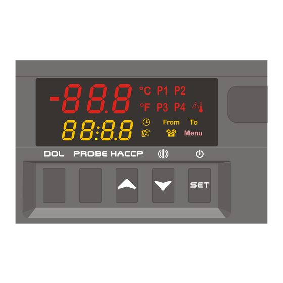
3. XDL01 FRONT PANEL COMMANDS
-
In programming mode it
operation. To start and stop recording, if the parameter rdb = y..
(UP): To see the data recorded.
In programming mode it browses the parameter codes or increases the
displayed value.
(DOWN) To see the alarms recorded.
In programming mode it browses the parameter codes or decreases the
displayed value.
DOL
To download the data to the USB pen drive.
PROBE
To select the probe to see the data
1592010270 XJDL40D GB r1.1 19.09.2012.doc
selects a parameter
or confirm an
XJDL40D - XDL01
KEY COMBINATIONS
+
To enter in programming mode.
+
To return to the room temperature display
To start the recognition of the controller connected to the
XDL01
+
DOL
To disable the alarm relay.
3.1 USE OF LEDS
LED
P1
Probe 1
P2
Probe 2
P3
Probe 3
P4
Probe 4
Clock symbol
Data symbol
XDL01 is recording
To signal the access to the "Function Menu"
Start date
End date
An alarm is happening
Celsius
Fahrenheit
4. WIRING CONNECTION
4.1 CONNECTION BETWEEN XJDL40D AND XDL01
MODEL WITH 9-40VDC SUPPLY (XJDL40D- 3xxxx)
Power supply: 11(-), 12(+)
Digital inputs:
-
I.D.1: 5(+), 6(-)
-
I.D.2: 7(+), 6(-)
-
I.D.3: 8(+), 9(-)
-
I.D.4: 10(+), 9(-)
Terminal 16: supply for P4 probe: the terminal number 16 supplies the same
voltage of the main supply of the instrument.
Warning: if the controller is powered with 40Vdc the voltage at terminal number 16
ia 40Vdc.
5. FIRST START UP
After connecting the XDL40D and XDL01 as described in the above paragraph,
parameters of XDL01 and XJDL40D have to be set.
Note: the parameters of XDL01 are accessible via XDL01.
5.1
XDL01: HOW TO SET THE RTC – TIME AND DATE
When the instrument is turned on, it's necessary to set the time and date.
In this case the controller displays the "rtc" message.
Push a key and then the following messages are displayed:
Upper Display
Lower Display
FUNCTION
Hur
value (flashing)
1/4
Advertisement

Subscribe to Our Youtube Channel
Related Manuals for Emerson dixell XJDL40D


Summary of Contents for Emerson dixell XJDL40D
- Page 1 KEY COMBINATIONS Data acquisition and recording modules XJDL40D AND XDL01 To enter in programming mode. To return to the room temperature display INDEX To start the recognition of the controller connected to the GENERAL WARNING ___________________________________________ 1 XDL01 GENERAL DESCRIPTION _______________________________________ 1 To disable the alarm relay.
- Page 2 7. XDL01 AND XJDL40D: PROGRAMMING MENU Push the UP or DOWN keys to adjust the hour. Push the SET to confirm the value. 7.1 TO ENTER IN PARAMETERS LIST “PR1” ((XDL01 E XJDL40D) Repeat the same operations for the next parameters: To enter the parameter list “Pr1”...
- Page 3 Probe 3 presence no = probe absent; YES = probe present 9.2 DATA VISUALISATION Probe 3 calibration (-12,0°C ÷ 12,0°C; -21°F ÷ 21°F); allows to adjust Push and release the UP key (HACCP) possible offset of the probe 3. The P1 or P2 or P3 or P4 is lighted (it depends on which probe has been Kind of probe 4;...
- Page 4 16. PARAMETERS 11.2 ALARM FILE STRUCTURE DESCRIPTION LABEL START STOP Nome Description Range Value Level High temperature 19/05/08 16.34 19/05/08 16.44 Serial address 0÷247 No link 19/05/08 16.53 19/05/08 16.57 Recording interval 10÷255min 16min No link 19/05/08 15.52 19/05/08 15.59 First probe recording enable y÷n High temperature...
Need help?
Do you have a question about the dixell XJDL40D and is the answer not in the manual?
Questions and answers