Table of Contents
Advertisement
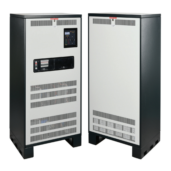
LiteMinder Modular/
LiteMinder Optimus
3KW -33.0KW
MULTI-PHASE
SPLIT/TWO and
THREE PHASE
MODELS
IMPORTANT SAFEGUARDS
When using electrical equipment, basic safety precautions should always be
followed including the following:
READ AND FOLLOW ALL SAFETY INSTRUCTIONS
A.
Do not use outdoors
B.
Do not mount near gas or electric heaters.
C.
Use caution when servicing batteries. Battery acid can cause burns to
skin and eyes. If acid is spilled on skin or in eyes, flush acid with fresh
water and contact a physician immediately.
D.
Equipment should be mounted in locations and at heights where it will
not readily be subjected to tampering by unauthorized personnel.
E.
The use of accessory equipment not recommended by the
manufacturer may cause an unsafe condition.
F.
Do not use this equipment for other than intended use.
This unit contains lethal voltages. There are no user serviceable parts inside.
Only authorized service personnel are to be used for service.
The installation and use of this product must comply with all national, state,
municipal or local codes that apply. Please read this manual thoroughly
before installing and operating the LM/LMOPT Series central inverter system.
For assistance please call EVENLITE technical support at 800-967-5573 and
speak to a technician during normal business hours (EST).
2575 Metropolitan Drive • Trevose, PA • 19053 U.S.A
Installation / Operation Manual
Emergency Lighting Central
Inverter System
SAVE THESE INSTRUCTIONS
Telephone: (215) 244-4204 • Fax: (215) 244-4208
by
8KW MODEL
SHOWN
Advertisement
Table of Contents

Related Manuals for Evenlite LiteMinder Modular


Summary of Contents for Evenlite LiteMinder Modular
- Page 1 Please read this manual thoroughly before installing and operating the LM/LMOPT Series central inverter system. For assistance please call EVENLITE technical support at 800-967-5573 and speak to a technician during normal business hours (EST).
-
Page 2: Table Of Contents
TABLE OF CONTENTS 8.0 Specifications 1.0 Introduction 1.1 Mechanical Design Features 9.0 Warranty 1.2 Electrical Design Features 9.1 Technical Service and Support 1.3 Phase Configurations 9.2 Return Material Authorization (RMA) 2.0 Receiving and Storage 2.1 Inspection 10.0 Man Machine Interface (MMI) 2.2 Storage 10.1 Introduction 10.2 System Test Button... -
Page 3: Introduction
1.0 INTRODUCTION The LM/LMOPT Central Inverter System integrates the latest power electronics and microprocessor technology and produces a pure sine wave power output intended for use in Emergency Lighting. The system is very efficient on-line and typically has a standby power loss of only 2 percent of the systems total capacity. -
Page 4: Phase Configurations
1.3 Phase Configurations The LM/LMOPT Central Inverter System is a modular design which can produce many different configurations of voltages. Since all of the modules AC outputs have a common neutral point, modules can be arranged in a split-phase (180° phasing) with two modules, two phase (120° phasing) with two modules, and three phase (120°... -
Page 5: Receiving And Storage
2.0 RECEIVING AND STORAGE 2.1 Inspection The LM/LMOPT Series central inverter and batteries are shipped together unless specified with the “ship-less batteries” option code(-UP). Upon arrival, please inspect the contents to ensure that no shipping damage has occurred. This is especially important with batteries – ensure that there are no cracks or leaks. -
Page 6: Installation
3.0 INSTALLATION 3.1 Location NEC article 700 EMERGENCY CIRCUITS should be referenced for proper installation of a central inverter system. Article 700 dictates that unit must be mounted in a permanent location. Choose a cool dry place with normal ventilation and one which will allow easy access for testing and maintenance. Avoid a location which could allow vandalism and tampering. -
Page 7: Ventilation
Ohm-Meter to check that continuity between conduit and protective earth ground has been established. Seismic bracing is available for the LM/LMOPT Series. Please see Evenlite.com for details of seismic dimensions and configurations. Note – Cabinet sizes and construction may change due to optional features such as mixed voltages which require Isolation Transformers and/or Auto- Transformers. - Page 8 Cabinet Configurations (cont.) Size 1 2.2KW, 3KW Size 2 4.2KW, 5.2KW, 6.25KW, 8.25KW, 10.5KW, Size 3 12.5KW 15.75KW, 18.75KW Size 4 10.5KW, 13.3KW, 17.0KW (LMOPT) Size 5 20.5KW, 26.5KW, 33.0KW (LMOPT) Note – Standard cabinet configurations for all sizes are shown. Other cabinet configurations may be used when optional features are provided such as mixed Input/Output voltages which requires isolation or auto-type transformers.
- Page 9 SIZE 2 4.2KW, 5.2KW, 6.25KW, 8.25KW, 10.5KW, 12.5KW Split/Two Phase Models 4.2KW, 5.2KW, 6.25KW, 8.25KW, 10.5KW, 12.5KW Three Phase Models LM/LMOPT SERIES | 9...
- Page 10 SIZE 3 15.75KW, 18.75KW Three Phase Models 10 | INSTALLATION / OPERATION MANUAL...
- Page 11 SIZE 4 8.5KW, 10.5KW, 13.3KW, 17KW Three Phase Models LM/LMOPT SERIES | 11...
- Page 12 SIZE 5 20.5KW, 26.5KW, 33KW Three Phase Models 12 | INSTALLATION / OPERATION MANUAL...
-
Page 13: Ac Connections
4.0 AC CONNECTIONS WARNING – Only qualified personnel that are familiar with AC and DC installation techniques and codes (such as an electrician) should perform the Installation. WARNING – The LM/LMOPT Series contains lethal AC Voltages. Due to the hazard of high voltage electrocution, always shut down all sources of power before you install, maintain, or service the unit. -
Page 14: Installing The Output Wires
4.3 Installing the Output Wires Connect the load wires to the Normally-On output terminal blocks. If your system has output breakers, connection directly to these circuit breakers are permitted since these are also UL489 rated. Other output configurations could include Normally-Off or Switched outputs which also use circuit breakers as the connection points. - Page 15 SIZE 1 - Can accommodate up to 6 output breakers without trip alarms, 4 output breakers with trip alarms. Output circuit breakers can be configured as Normally-On, Normally-Off and Switched-Output types. See Ordering Guide in Section 8 for your specific breaker configurations. Breaker type(s) quantity may be limited due to other installed optional features.
- Page 16 SIZE 2/3 - Can accommodate up to 24 output breakers without trip alarms – 18 output breakers with trip alarms. Output circuit breakers can be configured as Normally-On, Normally-Off and Switched-Output types. See Ordering Guide in Section 8 for your specific breaker configurations.
- Page 17 SIZE 4/5 - Can accommodate up to 36 output breakers without trip alarms – 24 output breakers with trip alarms. Output circuit breakers can be configured as Normally-On, Normally-Off and Switched-Output types. See Ordering Guide in Section 8 for your specific breaker configurations. Breaker type(s) quantity may be limited due to other installed optional features.
-
Page 18: Battery And Dc Connections
BATTERY AND DC CONNECTIONS WARNING – Only qualified personnel that are familiar with AC and DC installation techniques and codes (such as an electrician) should perform the Installation. WARNING – Remove all rings, watches, and other jewelry before doing any electrical service or installation work. - Page 19 Battery Hardware All battery hardware required for the installation comes with the system. When installing the batteries and hardware, please ensure flat washers and lock washers are used with each bolt. Ensure that the batteries jumper busbars are seated flat against the surface of the batteries terminals before tightening and NEVER over-tighten the bolts by ensuring that proper torque is applied to the bolts.
- Page 20 Power Distribution Block Detail (Shelf 3) 3.0KW 3 -PHASE MODEL 4.2 KW TWO-PHASE SPLIT-PHASE MODELS 5.2 KW TWO-PHASE SPLIT-PHASE THREE-PHASE MODELS 20 | INSTALLATION / OPERATION MANUAL...
- Page 21 6.25 KW TWO-PHASE SPLIT-PHASE MODELS 8.25 KW TWO-PHASE SPLIT-PHASE THREE-PHASE MODELS LM/LMOPT SERIES | 21...
- Page 22 10.5 KW TWO-PHASE SPLITE-PHASE THREE-PHASE MODELS 12.5 KW TWO-PHASE SPLIT-PHASE THREE-PHASE MODELS 22 | INSTALLATION / OPERATION MANUAL...
- Page 23 LM/LMOPT SERIES | 23...
- Page 24 24 | INSTALLATION / OPERATION MANUAL...
- Page 25 13.3KW MODEL LMOPT 10.5KW, 17KW MODEL LMOPT LM/LMOPT SERIES | 25...
- Page 26 26.5KW MODEL LMOPT 20.5KW 33KW MODEL LMOPT 26 | INSTALLATION / OPERATION MANUAL...
-
Page 27: Startup And Shutdown Procedures
6.0 STARTUP AND SHUTDOWN PROCEDURES 6.1 Startup After the unit is installed, the AC Input and Output wires landed and the batteries are installed and wired per Sections 3 - 5, the unit is ready to be started up. Ensure that the incoming AC voltage is reaching the unit by turning on all feed circuit breakers. -
Page 28: System Operation
7.0 SYSTEM OPERATION 7.1 Startup Mode When the LM/LMOPT Series is first turned on using the System ON/OFF switch, it goes through a sequence of self-tests which ensures proper connections are made and also checks for faults that may be present. The inverter must qualify several things before advancing to the Battery Charging mode. -
Page 29: Specifications
8.0 Specifications Input Voltage Model and Voltage Dependent (Tables 8.1 through 8.4) Current Model and Voltage Dependent (Tables 8.1 through 8.4) Frequency 60Hz +/- 2 Hz Protection Input Circuit Breaker standard Power Factor 0.5 lead to 0.5 lag Output Voltage Model and Voltage Dependent (Tables 8.1 through 8.4) Current Model and Voltage Dependent (Tables 8.1 through 8.4) - Page 30 30 | INSTALLATION / OPERATION MANUAL...
- Page 31 LM/LMOPT SERIES | 31...
- Page 32 32 | INSTALLATION / OPERATION MANUAL...
- Page 33 LM/LMOPT SERIES | 33...
- Page 34 Table 8.5 Battery Electrolyte Volume 34 | INSTALLATION / OPERATION MANUAL...
- Page 35 LM-2200W thru LM-12,500W Diagram 8.6 System One-Line Drawing Split/Two Phase LM-3000W thru LMOPT-33,000W Diagram 8.7 System One-Line Drawing Three Phase LM/LMOPT SERIES | 35...
-
Page 36: Warranty
9.0 WARRANTY There are two separate warranty periods for the LM/LMOPT Series Central Inverter System. The Electronics/Cabinet warranty period is for 2 years from the date of shipment. It is warranted against defects in workmanship and materials under normal and proper use. Batteries are covered under a separate warranty and these durations may change dependent on battery type. -
Page 37: Introduction
10.1 Introduction The Front Panel Man Machine Interface (MMI) consists of a 5 button keypad (Left Key, Up Key, Right Key, Down Key and Enter Key) for menu navigation, a 4x20 character backlit LCD display, Heads-Up LEDs for quick diagnosis of system status and alarms, Dedicated System Test pushbutton and Alarm Silence On/Off pushbutton. -
Page 38: System Test Button
10.2 System Test Button Pressing the System Test pushbutton will initiate a 30 second test of the system. This test will comply with the UL924 self-testing and self-diagnostics by analyzing battery voltages and output loads. All switched loads are energized during a system test. -
Page 39: Meter Menu
10.8 Meter Menu The following 11 functions are available through the Meter Menu. Input Voltage, Output Voltage, Output Current, Output VA, Battery Voltage, Battery Current, Battery Power, Temperature, System Days, Inverter Minutes and Inverter Events. Output Voltages and Currents are True-RMS measurements while Battery measurements use an Averaging technique. -
Page 40: Test Log
10.11 Test Log Identical to the Event Log with the exception that the Test Log is only stored when a system test is either: a) initiated from either a manual process of the User pressing the Test Button on the front panel keypad or, b) when the system is instructed by the automatic monthly or yearly test. - Page 41 Low VAC Alarm User can enable or disable this alarm by selecting the up or down arrow keys to “On” or “Off” and then press the Enter Key. If the user enables this alarm, the default setting is 85 percent of nominal AC line voltage but is fully adjustable. Using the up or down key, adjust the voltage to the desired level.
- Page 42 Load Reduction Alarm Load Reduction is an alarm available to quantify if Load Changes have occurred. When the Load Reduction option is enabled, the actual output current is compared to a user adjusted load current setting during an event only! It only looks at load current during an event because with modern lighting management, the loads can continuously change from Motion Sensors, Occupancy Sensors, etc.
-
Page 43: Maintenance And Service
11.0 MAINTENANCE AND SERVICE CAUTION – Whenever maintenance and service is to be performed, it may be desirable to shut the unit down. Please refer to Start up and Shut Down procedures for details. CAUTION – Always assume AC and DC Voltages are present at the LM/LMOPT Series terminals because the inverter is capable of providing output voltage from the batteries when there is no AC input present. -
Page 44: Battery Replacement
11.2 Battery Replacement LM/LMOPT Series is a UL approved and listed component with exact battery requirements. Failure to replace the batteries with the exact same type will VOID the UL approval. For battery replacement, please call the service number listed in Section 9 Warranty so that the unit performs as it was intended. -
Page 45: Web Interface
To logon to the LM/LMOPT series, simply go to Evenlite.com and click on the Inverter Monitoring link under the Resources drop-down menu and follow the User Setup instructions below. - Page 46 User Setup Page The user can change system parameters along with alarm trigger points and enable/disable alarms. The following features can be changed by the user: Date and Time settings(Year, Month, Day, Hour, Minute), Month Test Settings(Day, Hour, Minute) enable/disable, Year Test Settings(Month, Day, Hour, Minute) enable/disable, Low VAC Alarm enable/disable and set-point, High VAC Alarm enable/disable and set-point, Low Battery Alarm enable/disable and set-point, Near Low Battery Alarm enable/disable and set-point, Utility Failure Alarm enable/disable,...
- Page 47 Output VA Graphed in Min (Minimum) and Max (Maximum) readings for each hour and day. Min and Max values of Output VA can be selected/un-selected by mouse click and cause the graph to show both records simultaneously or one record at a time.
- Page 48 System Logs Page(s) The Inverter keeps a record of all critical events such as system tests and events and also any alarms that occur. The System Logs accessible are Test Logs, Event Logs, Alarm Logs and Discharge Logs. Alarm Logs Page Displays all of the Alarms sequentially so that number 1 was the most recent alarm.
Need help?
Do you have a question about the LiteMinder Modular and is the answer not in the manual?
Questions and answers