Advertisement
Contractors Guide
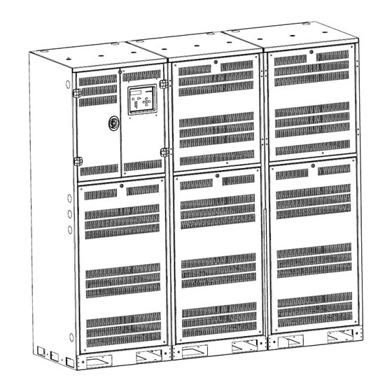
Emergency Lighting Central Inverter System
Step By Step Procedures
33,000 Watt/VA (Three Phase)
Installation Guidelines
5 Step Installation:
1.Mounting the Cabinet
2.Install / Connect Batteries
3.Install Conduit
4.Install AC Wiring
5.Energize System
For additional information, please refer to the Installation/Operation Manual
1
Technical Support / Installation Questions – Call 1-800-967-5573 (Monday-Friday, 8AM-5PM EST)
Advertisement
Table of Contents

Related Manuals for Evenlite LiteMinder Optimus


Summary of Contents for Evenlite LiteMinder Optimus
- Page 1 Contractors Guide Emergency Lighting Central Inverter System Step By Step Procedures 33,000 Watt/VA (Three Phase) Installation Guidelines 5 Step Installation: 1.Mounting the Cabinet 2.Install / Connect Batteries 3.Install Conduit 4.Install AC Wiring 5.Energize System For additional information, please refer to the Installation/Operation Manual Technical Support / Installation Questions –...
- Page 2 Overall Mounting and Product Outline Dimensions Technical Support / Installation Questions – Call 1-800-967-5573 (Monday-Friday, 8AM-5PM EST)
- Page 3 See page 5 for cabinet connections Access to Mounting Holes. Prepare floor so that it is level and smooth. Secure Inverter Cabinet into floor first, We recommend concrete wedge anchors such as the Hilti brand Wedge Anchor series Kwik Bolt TZ or equivalent. (Hardware provided by others). Note - Uneven surfaces may cause difficult front cover removal/installation Step 1.
- Page 4 Access to Mounting Holes through the floor of the battery cabinet. All 9 floor mounts should be installed. Use floor anchoring hardware to secure cabinet. (Supplied by contractor) Prepare floor so that it is level and smooth. Secure battery Cabinet(s) into floor using Concrete Wedge Anchors such as the Hilti brand Wedge Anchor series Kwik Bolt TZ or equivalent.
-
Page 5: Connecting The Cabinets
Supplied by Contractor Battery wire Port Insulating Cap 1-1/2’’ Chase Nipple Knocko 1-1/2’’ Nut Step 1 - Continued Connecting the Cabinets Technical Support / Installation Questions – Call 1-800-967-5573 (Monday-Friday, 8AM-5PM EST) -
Page 6: Check List
Check List Ensure that all the factory provided items are present and ready: Batteries – Inspect each battery to ensure no shipping damages have occurred. Battery Interconnect wires (pre-lugged) and String connection wires (black for negative, red for positive) Battery Fuse Busbars with hardware (bolt, flat washer, lock washer) Temperature Sensor busbar Tools required –... - Page 7 Reference below for safest loading and connection Procedure Nominal DC Voltage 192VDC (32 Batteries) 240VDC (40 Batteries) See Detailed Diagram on Cabinet Door Step 2. - Continued Installing and Wiring the Batteries Technical Support / Installation Questions – Call 1-800-967-5573 (Monday-Friday, 8AM-5PM EST)
- Page 8 2.0. Loading and Preparing Batteries for Connections Step 2. - Continued Installing and Wiring the Batteries Technical Support / Installation Questions – Call 1-800-967-5573 (Monday-Friday, 8AM-5PM EST)
- Page 9 2.1. Loading the Batteries Load all the batteries into the cabinet such that 4 batteries are on each shelf. 2.2. Spacing the Batteries Space the batteries equally and centered in the middle. Ensure proper alignment (front to back and side to side) for the bus bars to fit between the batteries on the battery terminals.
- Page 10 Installation of interconnection busbars 2.6. Outside Battery Busbar Connections – At this time, only install two busbars per shelf which connects the outside left two batteries and the outside right two batteries. Note – Leaving the middle connection open at this time will keep the DC voltage to a maximum of 48VDC at any point in the cabinet.
-
Page 11: Finalizing The Installation
2.8. Bottom Busbar - Connect the middle busbar to the bottom shelf. 2.9. Remaining Busbars - Connect the middle bus bar above the bottom shelf, and then connect the middle busbar to the shelf below the top battery shelf. 2.0.0 Final Busbar - If the system has 16 batteries, the connections are complete. - Page 12 Step 3. Installing the AC Conduit See Illustrations on page 2 Use Provided Knock-Outs located on Top of Inverter Cabinet. Note – Drilling into cabinets may VOID warranty - metal shavings can short circuit electronic components. Knock-Outs are 1-1/2" Input and Output Wires should be run in separate conduit per NEC. Follow all Local and National Electrical Codes (NEC) Step 4.
-
Page 13: Panel Removal
Step 1. Begin with unlocking and opening both doors on inverter cabinet Panel removal Technical Support / Installation Questions – Call 1-800-967-5573 (Monday-Friday, 8AM-5PM EST) - Page 14 Step by step guide to remove A/C module panels Step 2. Start by removing the 8 bolts on the breaker cover Panel removal - Continued Technical Support / Installation Questions – Call 1-800-967-5573 (Monday-Friday, 8AM-5PM EST)
- Page 15 Step 3. Remove Step 4. Remove the 5 bolts and 3 breaker cover nuts and remove A/C section cover Panel removal – Continued Technical Support / Installation Questions – Call 1-800-967-5573 (Monday-Friday, 8AM-5PM EST)
- Page 16 Single Pole output breakers Three Pole Input breaker Note: If inverter has a bypass switch input wires will land on the input terminal blocks Ground Termination Bus Bars Neutral Termination Bus Bars Note: The Neutral Bus Bars are on plastic standoffs Step 4 - Installing A/C Wiring Technical Support / Installation Questions –...
- Page 17 Step 5 Starting Up/Energizing the Unit Ensure batteries are installed and the wiring is checked per Step 2. Ensure AC Power is present and lighting loads are connected per Step 4. Flip on Input Circuit Breaker CB1. Flip on System's On/Off Switch located behind the right of the Interface Panel. The System will go through start up diagnostics and go into charge mode if there are no errors.
Need help?
Do you have a question about the LiteMinder Optimus and is the answer not in the manual?
Questions and answers