
Related Manuals for Fujitsu Flash-CAN-64P-M09-V2


Summary of Contents for Fujitsu Flash-CAN-64P-M09-V2
- Page 1 Flash-CAN-64P-M09-V2 Flash-CAN-64P-M09-V2 Evaluation Board Documentation Fujitsu Microelectronics Europe GmbH Rev. 3.4 Page 1...
- Page 2 Flash-CAN-64P-M09-V2 History Revision Date Author Comment V2.0 09.02.2000 New Document V2.1 11.05.2000 Shadings modified for default jumper settings to achive better printing, size of schematic adapted to A4. Signals DSR, RTS, CTS added in Chapter 1.7.2 V2.2 20.10.00 Layout Pinning refers to MB90F562 series V3.0...
- Page 3 1 year from the date of receipt by the customer. Should a Product turn out to be defect, Fujitsu Microelectronics Europe GmbH´s entire liability and the customer´s exclusive remedy shall be, at Fujitsu Microelectronics Europe GmbH´s sole discretion, either return of...
- Page 4 Microelectronics Europe GmbH´s and its suppliers´ liability is restricted to intention and gross negligence. NO LIABILITY FOR CONSEQUENTIAL DAMAGES To the maximum extent permitted by applicable law, in no event shall Fujitsu Microelectronics Europe GmbH and its suppliers be liable for damages whatsoever (including without limitation,...
-
Page 5: Table Of Contents
1.7.1 Edge connectors J16, J17, J18, J19 1.7.2 Serial Interface connectors X2, X3 1.7.3 Power connector X1 1.7.4 CAN Interface connector X4 2.0 INSTALLATION 3. SCHEMATICS AND DRAWINGS 3.1 Top Assembly Flash-CAN-64P-M09-V2 evaluation board 3.2 Schematics of Flash-CAN-64P-M09-V2 evaluation board (Pinning of MB90F562) Page 5... -
Page 6: Hardware Description
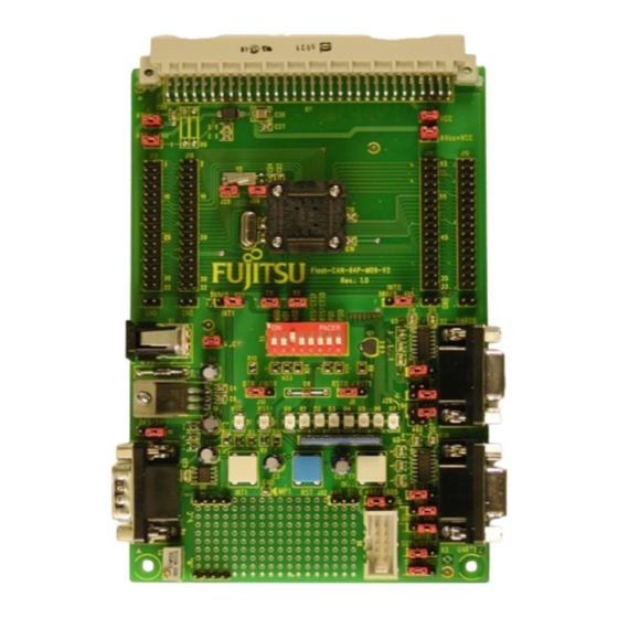
Flash-CAN-64P-M09-V2 1. Hardware description 1.1 Overview The Flash-CAN-64P-M09-V2 is a low cost multifunctional evaluation board for the Fujitsu 16-Bit Flash microcontroller series MB90560, MB90565, MB90460 and MB90495G. It can be used stand alone for software development and testing or as a simple target board to work with the emulator system. - Page 7 Flash-CAN-64P-M09-V2 FPT-64P-M09 (square QPF64 package, 0,65mm pitch) By default the board is working with a 4MHz crystal as the main oscillation clock, so internal clock rates up to 16MHz can be generated using the internal PLL of the AC. Two separate RS232 transceivers can be used to connect directly the two on- chip UARTs to the 9 pin D-Sub connectors.
-
Page 8: Jumpers And Switches
Flash-CAN-64P-M09-V2 1.4 Jumpers and Switches This chapter describes all jumpers and switches which can be modified on the evaluation board. The default setting is shown with a gray shaded area. All jumpers and switches are named directly on the board by its meaning, so it is very easy to set the jumpers according to the features. -
Page 9: Power Supply Voltage (J1, J7)
Flash-CAN-64P-M09-V2 ON (closed) 0 (low) P00 (S1/8) OFF (open)* 1 (high) Figure 2: S1 DIP switch setting for the Port P00 and P01 (default: P01= 0FF, P00 = OFF) 1.4.2. Power Supply Voltage (J1, J7) The evaluation board can be configured to work with +3.3V or +5.25V power supply voltage. -
Page 10: Define External Interrupts Int0, Int1 (J8, J24)
Flash-CAN-64P-M09-V2 OFF (open) Power supply Vcc disconnected from the AC Figure 4: J7 jumper setting for Vcc power Supply (default: J7= 0N) The Jumper JC is used to connect the on-board line regulator to the Vcc line. Open this Jumpr when using own power supply... -
Page 11: Configuration Of The Rs232 Interfaces (J20 - J23, S1)
Flash-CAN-64P-M09-V2 1.4.4 Configuration of the RS232 Interfaces (J20 - J23, S1) J20 – J23, JA, JB are used to connnect the two on board serial transceivers to the UART0 and 1 interface of the microcontroller. J20, J2, JA and JB are used to connect the UART0 interface, J22 and J23 are used to connect the UART1 interface. -
Page 12: Reset Generation (J9, J10)
Flash-CAN-64P-M09-V2 Jumper JU and JV are used to select if DTR or RTS is connected to the RTS line of the RS232 transciever. Jumper setting Description 1-2 DTR* DTR selected for UART0 RTS0 (JU) 2-3 RTS RTS selected for UART0... - Page 13 Flash-CAN-64P-M09-V2 Note: If a Reset is active, the red Reset LED is lit. During normal operation this LED should be off! If the reset LED is steadily on, change the DTR polarity or remove the jumper completely and check the power supply input voltage.
-
Page 14: Configuration Of The Analog Interface (J2, J3, J4)
Flash-CAN-64P-M09-V2 1.4.6 Configuration of the analog Interface (J2, J3, J4) The jumpers J2, J3 and J4 are used to configure the analog interface. J2 is used to connect the analog ground AVss to the digital GND, J3 is used to connect the analog power supply voltage AVcc to Vcc. -
Page 15: Subclock Crystal (J25, J26)
Flash-CAN-64P-M09-V2 1.4.7 Subclock crystal (J25, J26) The jumpers J25 and J26 are used to connect the subclock crystal to the MB90495G. If the MB90560, MB90565 or MB90460 series is used, these jumpers have to be removed, because no subclock is supportet on these series. -
Page 16: Serial Asynchr. Programming Interface
UART1 interface. The MB90F462 can be programmed with UART0 interface. Therefore a special software PC frontend must be used which is available on the Fujitsu Micros CD-ROM. To prepare the evaluation board for the serial asynchr. programming, the following... -
Page 17: Flash Programming Socket
SCK1. 1.5.1 Flash Programming Socket On this board also a Flash Programming socket (X6) is mounted. So, it is possible to plug in directly the Fujitsu Flash Programmer, Flashkit. AD00 1 2 AD01... - Page 18 Flash-CAN-64P-M09-V2 When using the Flash Programming socket, the Jumper JX1, JX2 JD and JE must set accordingly to following tables. (UART selecting) Remove Resistor Array N1 at port0. SOT, SIN selection Jumper Setting Description 1-2* SIN1 ( SIN of UART1 selected)
- Page 19 Flash-CAN-64P-M09-V2 1.6 Related Products Flash-CAN-64P-M09-V2 Evaluation board for MB90560, MB90495G and MB90460 Series MB2141A Emulator debugger main unit MB2145-507 Emulation pod MB2132-461 Emulator probe cable for QFP package (FPT- 64P-M09) MB90V560CR Evaluation chip for MB90560 series for in- circuit emulator debugger...
-
Page 20: Connectors
Flash-CAN-64P-M09-V2 1.7 Connectors 1.7.1 Edge connectors J16, J17, J18, J19 The following table shows the pinning of the edge connectors J16-J19. The pins of the QFP-64 package are directly connected to these connectors. J16 and J17 are connected to the pins 1-32, J18 and J19 are connected to the pins 33-64 of the AC. - Page 21 Flash-CAN-64P-M09-V2 Connector-Pin cross reference table for MB90560 series Connector VG - CC Pin QFP 64 (MB90560) J16/J18 connector (J17/J19) P45/PPG4 P46/PPG5 P50/AN0 P51/AN1 P52/AN2 P53/AN3 P54/AN4 P55/AN5 P56/AN6 P57/AN7 AVCC AVSS P60/SIN1 P61/SOT1 P62/SCK1 P63/IN7/DTT1 RSTX P10/INT0 P11/INT1 P12/INT2 P13/INT3...
- Page 22 Flash-CAN-64P-M09-V2 P14/INT4 P15/INT5 P16/INT6 P17/FRCK P20/TIN0 P21/TO0 P22/TIN P23/T01 P24/IN0 P25/IN1 P26/IN2 P27/IN3 P30/RTO0 P31/RTO1 P32/RTO2 P33/RTO3 P34/RTO4 P35/RTO5 P36/SIN0 P37/SOT0 P40/SCK0 P41/PPG0 P42/PPG1 P43/PPG2 P44/PPG3 Page 22...
-
Page 23: Serial Interface Connectors
Flash-CAN-64P-M09-V2 1.7.2 Serial Interface connectors X2, X3 The following diagram shows the connection of the 9-pin D-Sub female connectors X2 and X3 which are used for the serial interfaces GND DTR RXD TXD TXD is the transmit output, RXD is the receive input. The DTR signal is used as an input ,which can be connected to generate a reset. -
Page 24: Can Interface Connector X4
Flash-CAN-64P-M09-V2 1.7.4 CAN Interface connector X4 The following diagram shows the connection of the 9-pin D-Sub male connector X4 which is used for the CAN interface CANL CANH For the CAN interface the resistor trimmer P1 is used to adjust the slew rate. Take care that the slew rate is adjusted according to the local environment (CAN network configuration, transfer rate). -
Page 25: Installation
Flash-CAN-64P-M09-V2 2.0 Installation Carefully remove the board from the shipping carton. Check first if there are any damages before power on the evaluation board. Note: For the power supply a DC input voltage of about 7,5V is recommended. The positive voltage (+) must be connected to the shield, and ground (GND) must be connected to the centre of the connector X1! After power-on, the green power-on LED should be on. -
Page 26: Schematics And Drawings
Flash-CAN-64P-M09-V2 3. Schematics and Drawings 3.1 Top Assembly Flash-CAN-64P-M09-V2 evaluation board Page 26... - Page 27 Flash-CAN-64P-M09-V2 3.2 Schematics of Flash-CAN-64P-M09-V2 evaluation board (Pinning of MB90F562) J1 6 J1 7 J1 8 J1 9 Pin 1 Pin 2 Pin 1 Pin 2 Pin3 3 Pin3 4 Pin3 3 Pin3 4 Pin 3 Pin 4 Pin 3...
Need help?
Do you have a question about the Flash-CAN-64P-M09-V2 and is the answer not in the manual?
Questions and answers