
Related Manuals for Advanced Illumination PULSAR 320E


Summary of Contents for Advanced Illumination PULSAR 320E
- Page 1 PULSAR 320E STROBE CONTROLLER OPERATION AND MAINTENANCE MANUAL Version 4 10/4/2023...
-
Page 2: Table Of Contents
Running the Software File Menu Device Menu Device Information Advanced Settings Windows Pulsar 320E Utility Dialog Box Status Indicators Pulsar 320E User Interface Output Controls USB Control 4.10 Host Computer Control (Host) 4.11 External Trigger Interface 5 INPUTS AND OUTPUTS... - Page 3 7 REGULATORY REQUIREMENTS AND COMPLIANCE 7.1 Compliance Information 7.2 Warranty Information information 7.3 Return Policy 7.4 Electromagnetic Compatibility 7.5 Customer Service 8 APPENDIXES APPENDIX A: Trigger connection Diagram APPENDIX B: Pulsar 320E TCP/IP Setup Instructions APPENDIX C: Definition of Terms Page 3 of 33...
-
Page 4: Description
Pulsar 320E Operation and Maintenance Manual DESCRIPTION KEY FEATURES – PULSAR 320E 1.1.1 The Pulsar 320E provides the ultimate in lighting control for strobe-only, high power applications. 1.1.2 Two outputs for controlling 2 lights independently, each capable of 50A @ 100V DC. -
Page 5: Specifications
Pulsar 320E Operation and Maintenance Manual SPECIFICATIONS Controller Style Discrete Control System (External, Detachable) User Interface Software GUI Operating Modes Pulsed (Overdrive Strobe), Repeat Pulsed Light Head Connection Via Proprietary Header Block with Embedded EEPROM in light head connector (C5 connector) Input Supply 24V DC Nominal, Minimum 4.0A Recommended... - Page 6 *Values shown are based on controller component limitations. Actual limitations will vary depending on the limits set for the connected light head. These limits are determined using Advanced Illumination's proprietary SignaTech™ (Signature Technology) in order to ensure safe peak performance.
-
Page 7: Hardware
Pulsar 320E Operation and Maintenance Manual HARDWARE PULSAR 320E OVERVIEW AND DIMENSIONS Figure 2. Pulsar 320E Dimensions Page 7 of 33... -
Page 8: Controller Architecture
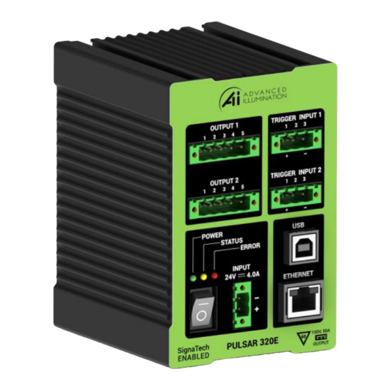
PULSAR 320E CONTROLLER CABLE CONNECTIONS Four physical connections, one of which needs to be a USB or Ethernet will be required to operate the Pulsar 320E and light head. Refer to figure 1 for an illustration of the Pulsar 320E’s front panel. 2.4.1 Power:... -
Page 9: Trigger
2.4.4 USB: The USB connector is located to the right and center of the front panel. A host computer will communicate with the Pulsar 320E via this USB connection. Connect the provided USB cable between the USB connection on the host computer and the connector labeled USB on the Pulsar 320E. -
Page 10: Light Head
Pulsar 320E Operation and Maintenance Manual HARDWARE SETUP MOUNTING The Pulsar 320E controller has an integrated 35mm din-rail clip. The clip is non-removeable and can be actuated with a flat-blade screwdriver or similar tool, located towards the bottom of the controller. Figure 6. Mounting Clip... -
Page 11: Software
Pulsar 320E Controller user interface software is required to set the operational parameters of the Pulsar 320E. This utility program is included online at our website and is installed as follows: Note: Administrator Access to the system is usually required to install the software. -
Page 12: Running The Software
Pulsar 320E Operation and Maintenance Manual 4.1.2 Select Setup_Pulsar320E_Control.exe Figure 8. Software Install Window 4.1.3 Close all open applications if prompted and press Next. RUNNING THE SOFTWARE 4.2.1 Launch Pulsar 320E Control 4.2.2 Choose USB 4.2.3 Select a USB port. Use port 0 by default. Click “Connect”. - Page 13 Pulsar 320E Operation and Maintenance Manual Figure 9. Pulsar Control 4.2.4 Upon connecting to a USB Port, the output configuration sections will be enabled – Grayed out outputs means no light is connected. Figure 10. Pulsar Control Page 13 of 33...
-
Page 14: File Menu
Pulsar 320E Operation and Maintenance Manual 4.2.5 Test the light head: 4.2.5.1 Set the output Mode to Setup. 4.2.5.2 Click Program in the upper right. 4.2.5.3 The light head should enter a continuous current mode that will allow for visible detection that the light is working. -
Page 15: Device Information
Pulsar 320E Operation and Maintenance Manual DEVICE INFORMATION Figure 13. Device Information ADVANCED SETTINGS WINDOW Figure 14. Advanced Settings 4.6.1 Slew Rate: used to reduce output ripple/ringing on the output light pulse. Using the proper slew rate setting may improve lighting performance. Note: for most applications, it is not required to change this setting. -
Page 16: Pulsar 320E Utility Dialog Box Status Indicators
Pulsar 320E Utility Dialog Box Status Indicator Output: Output 1 and Output 2 group boxes will appear active (not grayed-out) to indicate there is a light head connected to the Pulsar 320E. The type of light head will also be displayed when available. -
Page 17: Usb Control 118
USB Control 4.9.1 Connect Pulsar 320E USB cable to host PC, 24vDC, and applicable light head 4.9.2 Switch the main rocker power switch ON. A green power LED will illuminate, followed by a flashing amber LED. -
Page 18: Host Computer Control (Host)
Refer to Appendix “A” Figure 21 for common trigger connection schematics. When utilizing a single ended trigger source it is important to realize that the Pulsar 320E requires a “sourcing” output (PNP or Pull Up) as the trigger input is “sinking”. - Page 19 200 nanoseconds. 4.11.1 Alternate Trigger Configurations: If the Pulsar 320E will be triggered by a PLC refer to Appendix “A” for schematics depicting different PLC configurations. Page 19 of 33...
-
Page 20: Inputs And Outputs
Pulsar 320E Operation and Maintenance Manual INPUTS AND OUTPUTS INPUTS Power Input Pin Function Notes 24VDC 4A recommended minimum for best performance Figure 17. Power Connector DC GND External Trigger Input Function SIG + SIG - Figure 18. External Trigger Connector... -
Page 21: Troubleshooting
24VDC power connection. 6.1.2 Amber The amber light indicates the operational status of the Pulsar 320E. A blink rate of once per second indicates normal operation. A blink rate of 5 times per second indicates an error condition. -
Page 22: Error Codes
219 indicate that internal voltage levels are not correct. If these, or any codes other than those listed above occur, contact Technical Support at Advanced illumination for assistance. Under no circumstances should the user attempt repairs on the unit. -
Page 23: Regulatory Requirements And Compliance
COMPLIANCE INFORMATION WARRANTY INFORMATION Every Advanced illumination, Inc. (Ai) product is thoroughly inspected and tested before leaving the factory. Products are warranted to be free of defects in workmanship and materials for a period of FIVE YEARS from the original date of purchase. Should a defect develop during this period, customers may return the complete product, freight prepaid, to one of Ai’s distributors or to the Ai... -
Page 24: Customer Service
Friday 8:00 am to 5:00 pm ET or send an email to orders@advancedillumination.com. Company Information Advanced Illumination 440 State Garage Road, Rochester, VT 05767 Phone: 802.767.3830 Fax: 802.767.2636 Email: info@advancedillumination.com Web: advancedillumination.com © 2021 Advanced illumination Inc. All rights reserved Page 24 of 33... -
Page 25: Appendixes
Pulsar 320E Operation and Maintenance Manual APPENDIXES Appendix A: Trigger Connection Diagram Appendix B: Pulsar 320E TCP/IP Setup Instructions Appendix C: Definition of Terms Page 25 of 33... -
Page 26: Appendix A: Trigger Connection Diagram
Pulsar 320E Operation and Maintenance Manual APPENDIX A: TRIGGER CONNECTION DIAGRAM TYPICAL PULSAR TRIGGER WIRING 24VDC - External Trigger Source Ai Pulsar 320E VIN - VIN + R PULL UP 4.8 -10k 1 TRIG IN 2 TRIG DIF OUT COM 3 GND 3 Typical NPN –... -
Page 27: Appendix B: Pulsar 320E Tcp/Ip Setup Instructions
APPENDIX B: PULSAR 320E TCP/IP SETUP INSTRUCTIONS Configure network settings for the PC Connect through a network or router Direct connect with a single PC connection 2.0 Connection to the Pulsar 320E Pulsar 320E TCP/IP setup TCP/IP CONNECTION THROUGH NETWORK TO PULSAR 320E: PC SETUP Find your current IP address and determine whether it is static or dynamic: 1. - Page 28 Pulsar 320E Operation and Maintenance Manual 6. Under Active Connections, click “Ethernet” Figure 23. Access Type 7. Under Connection, click Details 8. Look for these entries in the list: • DHCP enabled. “No” means your IP address is static. “Yes” means it is dynamic.
- Page 29 Pulsar 320E Operation and Maintenance Manual 11. Select “Internet Protocol Version 4 (TCP/IPv4)” and click Properties. Figure 24. Ethernet Properties 12. Enable Obtain IP address automatically. Enable Obtain DNS automatically unless advised otherwise by your network administrator. Figure 25. Internet Protocol...
- Page 30 Static, then make note of the IP address, subnet mask, and default gateway. You will need to assign the Pulsar 320E network settings so they work in the same range. Dynamic, then assign a static IP address instead (covered in the following pages).
- Page 31 Pulsar 320E Operation and Maintenance Manual This may be handled by an administrative group or network engineers. Have this group assign an IP that you can use for both the host PC and target Pulsar 320E unit. This will prevent any IP conflicts from occurring.
-
Page 32: Appendix C: Definition Of Terms
Voltage when driven by high current pulses, VFWD can increase by 10 to 20 times. For this reason voltage levels at the Pulsar 320E output can be as high as 100 volts. A measure of temperature difference between the LED junction and the LED connection to an external heat sink. - Page 33 Hertz (cycles per second). Repetition rate is usually multiple times per second. A proprietary feature of Ai light heads and the Pulsar 320E. Signatech II identifies the type of light head connected to the Pulsar 320E and maintains safe operating limits for each type.
Need help?
Do you have a question about the PULSAR 320E and is the answer not in the manual?
Questions and answers