Advertisement
Quick Links
Advertisement

Related Manuals for Advanced Illumination DCS Series


Summary of Contents for Advanced Illumination DCS Series
- Page 1 DCS Series - Lighting Controller USER MANUAL...
- Page 2 Contents Hardware Overview ..............2 Specifications & Features............3 Lighthead Cable Description ............. 4 “C1” Cable Specifications ............4 Connections ................5 Trigger Connection Diagrams ........... 8 Modes of Operation ..............9 Quick Start ................11 Quick Start: Connect Power and Light ........12 Quick Start: To start with DHCP ..........
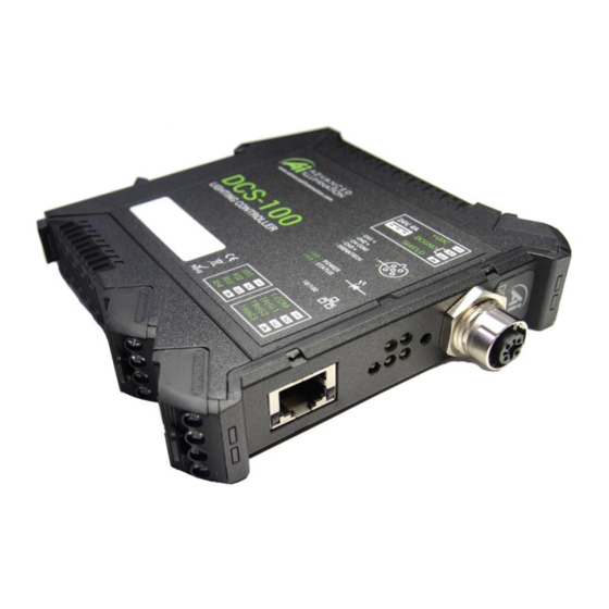
- Page 3 Hardware Overview Figure 1 - Installation and Interface DCS-100E User Manual 1595-050126 REVB 7/21/2015...
- Page 4 Specifications & Features Parameters Details Notes Input Power 24VDC Nominal, 4.5A 30VDC absolute maximum – exceeding 30VDC may result in damage to the controller Output Power 1.5A continuous per channel 5A strobe per channel Channel Control [3] Independently adjustable Channels Modes Pulsed, Continuous, or Gated Continuous...
- Page 5 Lighthead or controller. It is possible to bypass Signatech by using an authorized set of Signatch data and a software key provided by Advanced Illumination. Contact the factory for more information. Figure 2 – Controller with C1 Cable...
- Page 6 Connections Power Input (P1) Function Note 24V DC 4.5A recommended minimum for best performance. DC GND SHIELD Optional: Tied to chassis copper for ESD/EMI protection. Tie to earth ground if needed. Figure 3 – Power input Connector, P1 DCS-100E User Manual 1595-050126 REVB 7/21/2015...
- Page 7 External Trigger Input (P2) Function Note COMMON Common path for all trigger inputs Tie to a voltage level or ground depending on the type of external trigger TRIGGER 1 TRIGGER 2 TRIGGER 3 Notes: ~Trigger Inputs are bi-directional opto-isolated. ~All inputs are TTL- compliant, and are rated to +30VDC P3 IS RESERVED FOR FUTURE USE Figure 4...
- Page 8 Front Panel Color LED Behavior Function Green Solid Main power is connected Amber No light is connected Blinking @ 2Hz Heartbeat, device is ready Blinks twice Command received 3, 4, 5 Yellow External trigger signal is low External trigger signal is high BUTTON Type Button Behavior Function...
- Page 9 Trigger Connection Diagrams Figure 6 - Typical NPN / Emitter-Follower Connection Figure 7 - Typical NPN / Sinking Connection DCS-100E User Manual 1595-050126 REVB 7/21/2015...
- Page 10 Modes of Operation Continuous Continuous mode provides continuous illumination at the desired current. Light is always on unless a user issues a command to shut it off or the power is disconnected. Power is limited by the type of light that is connected and by the total power dissipation of the controller.
- Page 11 Gated Continuous This mode produces continuous illumination at the desired current, but the output follows the on-time of the external trigger signal. This mode is most useful to turn the light off during processes or in between inspections, or when longer pulse widths than pulsed mode will allow are needed.
- Page 12 Quick Start Typical Hardware Layout P1-Power P2-Trigger Figure 9 - Typical Hardware Setup For proper operation, make sure all connections are secure before applying power. DCS-100E User Manual 1595-050126 REVB 7/21/2015...
- Page 13 Quick Start: Connect Power and Light Connect 24V power supply leads to P1 and the illuminator to the output M12 connector. Connect trigger inputs to P2 if necessary. The Light contains a Signatech current-drive protection device in the molded M12 connector. This device is programmed to protect the light and govern the drive current.
- Page 14 Quick Start: To start with a Static IP Address: Power the controller without an Ethernet cable connected, or connected directly to a PC. The controller will begin with a default IP address of 192.168.0.1 Make sure the PC is using a STATIC IP connection. To assign a static IP in Windows, change your adapter settings in your network configuration to use a static ip under IPV4 Settings, See FIGURE11.
- Page 15 Quick Start: Graphical User Interface (GUI) Installation Install the software using the provided DCS-Setup application. Installation requires Microsoft .NET framework 4.0 or later. Figure 11 - DCS Software Installer DCS-100E User Manual 1595-050126 REVB 7/21/2015...
- Page 16 Quick Start: Using the GUI Pressing the devices drop-down box will ping the network for devices. The controller will scan for DCS controllers on the network, and will display any devices found in the dropdown menu. Select your device and press “Test Connection” to connect. Figure 12 &...
- Page 17 All channels can operate in a mixture of any mode. There are no restrictions. Figure 14 Output current is governed by Signatech , which are current drive restrictions implemented by Advanced Illumination. Note the different current limits depending on the mode used. Figure 15 DCS-100E User Manual 1595-050126 REVB 7/21/2015...
- Page 18 Continuous vs. Strobe Operation Strobe mode provides higher current limits than continuous. Using Signatech we can overdrive the output current higher. These values vary depending on the pulsewidth, current and type of light being used. In Strobe or Gated-Continuous modes, the output is triggered by an external device.
- Page 19 Quick Start: Other Features Renaming Devices: Devices can be renamed by clicking the “Devices” text. The part number and listed devices will be shown when opening this menu. Figure 17 Profiles: Configuration profiles can be saved by selecting a profile number and pressing save.
- Page 20 Ethernet Web Server After enabling the web server in the Software GUI, you can access the built-in web server from most internet browsers by entering the IP address of the controller in the browser address bar. Note that only the active configuration can be changed via the web server Figure 18 –...
- Page 21 Standard Ethernet Communication & Commands Default Ethernet Settings The Controller uses standard Ethernet protocol (TCP-IP and UDP) to communicate. The DCS control user interface can be used to communicate, or other software may be used to send data packets directly from the host to the controller. Setting Value Typical Port Settings...
- Page 22 Command Structure The DCS100 uses an SCPI-like interface where commands are a series of readable strings with parameters separated by commas. The strings must be terminated by a semicolon (‘;’) for proper operation. Commands with a parameter Commands that require a parameter have it separated by a comma. Example: “SET:LEVEL, 100;”...
- Page 23 Command Interface List Information / Help commands COMMAND DESCRIPTION RETURNS Advanced illumination Gets device information: firmware, hardware, etc.. “*IDN?;” “DCS-100: (fw version, hw version)” “*CHANNEL:CONFIGS?" Returns an XML formatted string: Reports the current, pulsewidth, delay, and trigger map settings on all channels “*PROFILE:NUMBER?”...
- Page 24 Channel Control Commands COMMAND DESCRIPTION RETURNS “SET:LEVEL:CHANNEL1, nnnn;” Sets the current in milliamps "SET:LEVEL:CHANNELc, nnnn" Where nnnn = 0-750 for continuous, 0- c = 1 - 3 (channel number) 3000 for strobe nnnn = 0-1500 (continuous &gated) nnnn = 0-3000 (strobe) Sets the mode c = 0 - 3...
- Page 25 Utility Commands COMMAND DESCRIPTION RETURNS "SAVE:PROFILE, n " Saves the profile in EEPROM INFO: Profile “n” has been saved. n = 0-5 (profile number) Updates all settings to the INFO: Name of profile 0 set to ' "LOAD:PROFILE" chosen profile test' INFO: Name of profile “n”...
- Page 26 Warranty Information Every Advanced illumination, Inc. (Ai) product is thoroughly inspected and tested before leaving the factory. Products are warranted to be free of defects in workmanship and materials for a period of two years from the original date of purchase. Should a...
Need help?
Do you have a question about the DCS Series and is the answer not in the manual?
Questions and answers