Table of Contents
Advertisement
Quick Links
Advertisement
Table of Contents

Subscribe to Our Youtube Channel
Summary of Contents for Advanced Illumination DCS-400E
- Page 1 Photometric Stereo with the Ai DCS-400E Quad Controller User Guide...
- Page 2 24 V DC Nominal, 4.5 A Vmin = 22 V DC Vmax = 48 V DC External Trigger Channel Control Input/Output DCS-400E: 4 Independent Channels, 1 Output 5 V, TTL Compatible DCS-800E: 8 Independent Channels, 2 Outputs Overtvoltage Protected, Safe up to 30 V DC...
-
Page 3: Table Of Contents
Table of Contents Introduction Hardware & Setup Hardware Overview Setup Diagram DCS-400E & DCS-800E General Specs DCS 400E Overview Modes Standard Sequenced Connections Camera Setup Design Assistant Software Setup Application Examples Threaded Metallic Part Inspection Glossy Vitamin Bottle Inspection Page 1... -
Page 4: Introduction
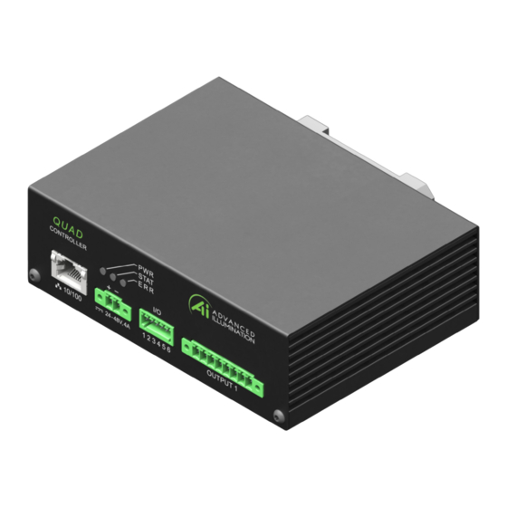
A typical photometric stereo imaging application uses two or more channels of lighting to sequentially illuminate the target from different directions. The DCS-400E and DCS-800E allow up to 4 or 8 potential channels, respectively, which can be used in any combination of quadrants or colors, or even different light types. -
Page 5: Setup Diagram
5A Pulsed per Channel; 12.5W per Channel 5A Pulsed per Channel; 12.5W per Channel Pulse Width Range 30 μsec - 3600 msec Strobe Frequency Limit 2KHz Trigger Latency 30 μsec Typical Download the User Manual for the DCS-400E & DCS-800E here: https://www.advancedillumination.com/quad-controllers-manual Page 3... -
Page 6: Dcs 400E Overview
Figure 1 - DCS-400E Standard Channel Settings, Single Event. If using DCS-800E, Channels 1-8 will be visible. Figure 2 - A Single Trigger Flashes each channel, with or without independent delay. Note: delay is not to scale with the channel settings shown in Figure 1. -
Page 7: Sequenced
(pulse delay, current, pulse width, etc.) associated with the receiving trigger. With the DCS-400E, each Event can include anywhere from 1-4 channels (DCS-800E includes 1-8 channels), with their respective settings (pulse delay, current, pulse width). For example, to set up a quadrant imaging application, the user should create x4 Events, one for each quadrant. -
Page 8: Connections
Connections Basic Camera to LC (Light Controller) Connections. Figure 5 - Camera Exposure Triggers LC Channels. Figure 6 - LC Triggered Externally, Frame-Start Triggers Camera Exposure. Camera Setup In the following examples, we are using a typical USB 3.0 camera with Matrox Design Assistant. The Quad Controllers are compatible with any camera and software combination that is capable of Photometric Stereo. -
Page 9: Design Assistant Software Setup
The full extent of using Matrox Design Assistant is beyond the scope of this User Guide. However, included in this document is a broad overview of how the DCS-400E Quad Controller and Ai lights work in conjunction with the Photometric Stereo library functions. -
Page 10: Application Examples
We independently control the quadrants of a DF198-115 MicroBrite Diffuse Ring Light with the DCS-400E Quad Controller to illuminate the threaded part from four directions. Figure 7 - Input images of the inspected threaded metallic part. -
Page 11: Glossy Vitamin Bottle Inspection
However, by using a DF198 MicroBrite Diffuse Ring Light with each of its four quadrants independently controlled with the DCS-400E Quad Controller, we are able to capture four images with illumination at the same angle of incidence, but from multiple directions. - Page 12 P: 802-767-3830 | F: 802-767-2636 | E: info@advancedillumination.com www.advancedillumination.com | 440 State Garage Rd., Rochester, VT 05767...


Need help?
Do you have a question about the DCS-400E and is the answer not in the manual?
Questions and answers