Table of Contents
Advertisement
Quick Links
Advertisement
Table of Contents

Related Manuals for MSI MS-7100


Summary of Contents for MSI MS-7100
- Page 1 K8N SLI Platinum MS-7100 (v1.X) ATX Mainboard G52-M7100XB...
-
Page 2: Fcc-B Radio Frequency Interference Statement
VOIR LA NOTICE D’INSTALLATION AVANT DE RACCORDER AU RESEAU. Micro-Star International MS-7100 This device complies with Part 15 of the FCC Rules. Operation is subject to the following two conditions: (1) this device may not cause harmful interference, and... -
Page 3: Copyright Notice
Copyright Notice T he material in this document is the intellec tual property of M ICRO-STAR INTERNATIONAL. W e take every care in the preparation of this document, but no guarantee is given as to the correctness of its contents. Our products are under continual improvement and we reserve the right to make changes without notice. -
Page 4: Technical Support
Alternatively, please try the following help resources for further guidance. † Visit the MSI homepage & FAQ site for technical guide, BIOS updates, driver updates, and other information: http://www.msi.com.tw & http://www.msi. -
Page 5: Table Of Contents
CONTENTS FCC-B Radio Frequency Interference Statement ............ii Copyright Notice ......................iii Revision History ......................iii Technical Support ......................iv Safety Instructions ......................iv English version ...................... E1-1 1. Getting Started ....................E1-3 2. Hardware Setup ..................... E2-1 3. BIOS Setup ...................... E3-1 French version ...................... - Page 6 Getting Started K8N SLI Platinum User’s Guide English E1-1...
- Page 7 M S-7100 ATX M ainboard E1-2...
-
Page 8: Getting Started
Getting Started Chap t er 1 . Ge tting Started Getting Started Thank you for choosing the K8N SLI Platinum (MS-7100) v1.X ATX mainboard. The K8N SLI Platinum mainboard are based ® on nVIDIA nForce™4 SLI chipset for optimal system efficiency. - Page 9 Mainboard Specifications † Supports Socket-939 for AMD K8 Athlon 64 FX / Athlon 64 (Socket939) processor † Supports up to 4000+ Athlon FX55 , or higher CPU (For the latest information about CPU, please visit http://www.msi.com.tw/program/ products/mainboard/mbd/pro_mbd_cpu_support.php) Chipset † nVIDIA nForce4 SLI...
- Page 10 Getting Started USB Interface † 10 USB ports - Controlled by nForce4 SLI chipset - 4 ports in the rear I/O, 6 ports via the external bracket NV RAID (Software) † Supports up to 4 SATA and 2 ATA133 Hard drives - RAID 0 or 1, 0+1, JBOD is supported - RAID function available for ATA133+SATA H/D or 4 SATA H/D drives †...
- Page 11 † ATX Form Factor (30.4 cm X 24.4 cm) M ounting † 9 mounting holes MSI Reminds You... To create a bootable RAID volume for a Windows 2000 environment, Microsoft’s Windows 2000 Service Pack 4 (SP4) is required. As the...
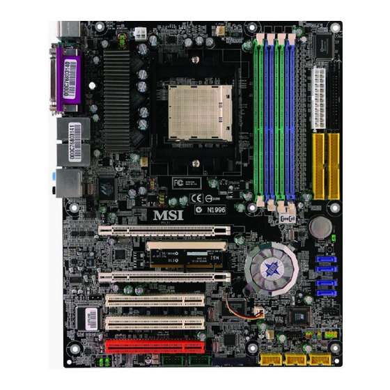
- Page 12 SATA4 PCI Slot 1 SATA3 NB_FAN1 VT6306 CREATIVE PCI Slot 2 JDB1 (Optional) Sound Bluster S_FAN2 PCI Slot 3 JFP1 JFP2 JLPC1 JUSB1 J1394_2 JUSB2 JUSB3 AUD1 J139 4_1 (Optional) (Option al) K8N SLI Platinum (MS-7100 v1.X) ATX Mainboard E1-7...
- Page 13 M S-7100 ATX M ainboard Packing Contents MSI Driver/Utility CD SATA RAID Driver SATA Cable/ Diskette/ Creative MSI motherboard Power Cable (Optional) Audio Driver D-Bracket 2 SLI Switch card SLI bridge (Optional) Round Cable of Round Cable of 1394 Cable...
-
Page 14: Hardware Setup
Hardware Setup Chapter 2. Hardware Setup Hardware Setup This chapter tells you how to install the CPU, memory modules, and expansion cards, as well as how to setup the jumpers on the mainboard. Also, it provides the instructions on connecting the periph- eral devices, such as the mouse, keyboard, etc. - Page 15 M S-7100 ATX M ainboard Quick Components Guide CPU, E-2-3 S_FAN1, E-2-16 DDR DIMMs, E-2-7 C_FAN1, JPWR2, E-2-16 E-2-10 JCI1, E-2-17 JIR1, E-2-20 Back Panel FDD1, E-2-16 I/O, E-2-12 JPWR1, E-2-10 IDE1/2,E-2-17 JCD1, E-2-18 PCI_E1, E-2-28 SW1, PCI_E4, E-2-27 E-2-24 SATA1~4, PCI_E3, E-2-28 E-2-18...
- Page 16 If you do not have the heat sink and cooling fan, contact your dealer to purchase and install them before turning on the computer. For the latest information about CPU, please visit http://www.msi.com.tw/pro- gram/products/mainboard/mbd/pro_mbd_cpu_support.php. MSI Reminds You...
- Page 17 M S-7100 ATX M ainboard CPU Installation Procedures for Socket 939 1. Please turn off the power and unplug the power cord before Open Lever installing the CPU. Sliding 2. Pull the lever s ideways away 90 degree Plate from the socket. Make sure to raise the lever up to a 90-de- gree angle.
- Page 18 Hardware Setup Installing AMD Athlon64/ Athlon64 FX CPU Cooler Set W hen you are installing the CPU, make sure the CPU has a heat sink and a cooling fan attached on the top to prevent overheating. If you do not have the heat sink and cooling fan, contact your dealer to purchase and install them before turning on the computer.
- Page 19 Safety Hook Fixed Lever Fixed Bolt MSI Reminds You... While disconnecting the Safety Hook from the fixed bolt, it is neces- sary to keep an eye on your fingers, because once the Safety Hook is disconnected from the fixed bolt, the fixed lever will spring back instantly.
- Page 20 The mainboard provides 4 slots for 184-pin DDR SDRAM DIMM (Double In-Line Memory Module) modules and supports the memory size up to 4GB. You can install DDR266/ 333/ 400 modules on the DDR DIMM slots (DDR 1~4). For the updated supporting memory modules, please visit http://www.msi.com.tw/ program/products/mainboard/mbd/pro_mbd_trp_list.php. DIMM1~4...
- Page 21 128MB~1GB 128MB~1GB 128MB~1GB 512MB~4GB MSI Reminds You... - Dual-channel DDR works ONLY in the 3 combinations listed in the table shown in the previous page. - Please select the identical memory modules to install on the dual channel, and DO NOT install three memory modules on three DIMMs, or it may cause some failure.
- Page 22 3. The plastic clip at each side of the DIMM slot will automatically close. Notch Volt MSI Reminds You... You can barely see the golden finger if the module is properly in- serted in the socket. E2-9...
- Page 23 Pin Definition SIGNAL JPWR2 MSI Reminds You... 1. These two connectors connect to the ATX power supply and have to work together to ensure stable operation of the mainboard. 2. Power supply of 450 watts (and above) is highly recommended for system stability.
- Page 24 Hardware Setup Important Notification about Power Issue NForce chipset is very sensitive to ESD (Electrostatic Discharge), therefore this issue mostly happens while the users intensively swap memory modules under S5 (power-off) states, and the power code is plugged while installing modules. Due to several pins are very sensitive to ESD, so this kind of memory-replacement actions might cause system chipset unable to boot.
- Page 25 M S-7100 ATX M ainboard Back Panel The back panel provides the following connectors: L-In RS-Out Parallel M ou se 1394 Port USB Ports SPDIF L-Out CS-Out Keyboard COM Port (optional) SPDIF Out (Coaxial) (Optical) Mouse Connector (Green) / Keyboard Connector (Purple) ®...
- Page 26 Hardware Setup Serial Port Connector The mainboard offers one 9-pin male DIN connector as the serial port. The port is a 16550A high speed communication port that sends/receives 16 bytes FIFOs. You can attach a serial mouse or other serial devices directly to the connector. Pin Definition 1 2 3 4 5 SIGNAL...
- Page 27 M S-7100 ATX M ainboard LAN (RJ-45) Jack The mainboard provides 1standard RJ-45 jack for connection to single Local Area Network (LAN). This Giga-bit LAN enables data to be transferred at 1000, 100 or 10Mbps. You can connect a network cable to the LAN jack. Giga-bit LAN Pin Definition SIGNAL DESCRIPTION...
- Page 28 Hardware Setup Parallel Port Connector: LPT1 The mainboard provides a 25-pin female centronic connector as LPT. A parallel port is a standard printer port that supports Enhanced Parallel Port (EPP) and Ex- tended Capabilities Parallel Port (ECP) mode. Pin Definition SIGNAL DESCRIPTION STROBE...
- Page 29 +12V +12V +12V +12V Sensor Sensor Sensor C_FAN1 S_ FAN1 S_ FAN2 NB_FAN1 MSI Reminds You... 1. Always consult the vendors for proper CPU cooling fan. ® 2. Please refer to the recommended CPU fans at AMD official website. E2-16...
- Page 30 IDE2 (Secondary IDE Connector) IDE2 can also connect a Master and a Slave drive. MSI Reminds You... If you install two hard disks on cable, you must configure the second drive to Slave mode by setting its jumper. Refer to the hard disk documentation supplied by hard disk vendors for jumper setting instructions.
- Page 31 Take out the dust cover and connect to the hard disk devices Connect to serial ATA ports MSI Reminds You... Please do not fold the serial ATA cable in a 90-degree angle, which will cause the loss of data during the transmission. CD-In Connector: JCD1 The connector is for CD-ROM audio connector.
- Page 32 Hardware Setup Front Panel Connectors: JFP1 / JFP2 The mainboard provides two front panel connectors for electrical connection ® to the front panel switches and LEDs. JFP1 is compliant with Intel Front Panel I/O Connectivity Design Guide. JFP1 Pin Definition SIGNAL DESCRIPTION HD_LED_P...
- Page 33 M S-7100 ATX M ainboard MSI Reminds You... Note that the pins of VCC and GND must be connected correctly, or it may cause some damage. Front Panel Audio Connector: AUD1 The AUD1 front panel audio connector allows you to connect to the front panel ®...
- Page 34 Hardware Setup IEEE 1394 Connectors: J1394_1 / J1394_2 (optional) The mainboard provides two 1394 pin headers that allow you to connect IEEE 1394 ports via an external IEEE1394 bracket. Pin Definition SIGNAL SIGNAL TPA+ TPA- Ground Ground J1394_1/ J1394_2 TPB+ TPB- Cable power Cable power...
- Page 35 M S-7100 ATX M ainboard D-Bracket™ 2 Connected to JDB1 (Optional) Connected to JUSB1, JUSB2 or JUSB3 LEDs (the USB pinheader in YELLOW color) D-Bracket™ 2 is an external USB bracket integrating four Diagnostic LEDs, which use graphic signal display to help users understand their system. The LEDs provide up to 16 combinations of signals to debug the system.
- Page 36 Hardware Setup Decompressing BIOS image to RAM for fast booting. Initializing Keyboard Controller. Testing VGA BIOS This will start writing VGA sign-on message to the screen. Processor Initialization This will show information regarding the processor (like brand name, system bus, etc...) Testing RTC (Real Time Clock) Initializing Video Interface This will start detecting CPU clock, checking type of video...
- Page 37 1. Turn the latch either right or left and the SLI switch card will spring upward instantly (refer to fig.2). Turn the latch to loose the card Fig.2 MSI Reminds You... Please make sure to turn off the system before you remove the SLI switch card. E2-24...
- Page 38 SLI bridge Fig.5 MSI Reminds You... 1. Install one graphics card to first PCI Express x 16 slot (PCI_E1) when non-SLI mode enabled. 2. When SLI mode was be enabled, to tear the sticker on the second- ary PCI Express x 16 slot (PCI_E3) and install the second graphics card to the slot (PCI_E3).
- Page 39 6. Finally, you've to reboot the system and you’ll see a information that inform you M ulti-GPU has been enabled. MSI Reminds You... If you want to remove one graphics card and change the status from SLI mode to normal, make sure that you have to unclick the "MultiGPU"...
- Page 40 Hardware Setup Button The motherboard provides the following jumpers for you to set the computer’s function. This section will explain how to change your motherboard’s function through the use of button. Clear CMOS Button: SW1 There is a CMOS RAM on board that has a power supply from external battery to keep the system configuration data.
- Page 41 M S-7100 ATX M ainboard Slots The mainboard provides two PCI Express x16 slot and three 32-bit PCI bus slots. PCI Express Slots: PCI_E1 & PCI_E3 The PCI Express slots, as a high-bandwidth, low pin count, serial, intercon- nect technology, support Intel highest performance desktop platforms utilizing the AMD processor.
- Page 42 Hardware Setup PCI Interrupt Request Routing The IRQ, acronym of interrupt request line and pronounced I-R-Q, are hard- ware lines over which devices can send interrupt signals to the microprocessor. The PCI IRQ pins are typically connected to the PCI bus INT A# ~ INT D# pins as follows: Order 1 Order 2 Order 3...
-
Page 43: Bios Setup
SETUP. ² You want to change the default settings for customized features. MSI Reminds You... 1. The items under each BIOS category described in this chapter are under c ontinuous update for better s y s tem performanc e. - Page 44 MSI Reminds You... The items under each BIOS category described in this chapter are under continuous update for better system performance. Therefore, the description may be slightly different from the latest BIOS and should be held for reference only.
- Page 45 BIOS Setup Control Keys <↑> Move to the previous item <↓> Move to the next item <←> Move to the item in the left hand <→> Move to the item in the right hand <Enter> Select the item <Esc> Jumps to the Exit menu or returns to the main menu from a submenu <+/PU>...
- Page 46 M S-7100 ATX M ainboard The Main Menu ® Once you enter Phoenix-Award BIOS CMOS Setup Utility, the Main Menu will appear on the screen. The Main Menu allows you to select from twelve setup func- tions and two exit choices. Use arrow keys to select among the items and press <Enter>...
- Page 47 BIOS Setup Load Fail-Safe Defaults Use this menu to load the default values set by the BIOS vendor for stable system performance. Load Optimized Defaults Use this menu to load the default values set by the mainboard manufacturer specifi- cally for optimal performance of the mainboard. BIOS Setting Password Use this menu to set the password for BIOS.
- Page 48 M S-7100 ATX M ainboard nVidis RAID Config nVidiaRAID Config Press <Enter> to enter the sub-menu and the following screen appears: RAID Enabled This item is used to enable/disable the onchip RAID function. W hen you set to enable and the following fields will be selectabled. Setting options: [Enabled], [Disabled].
- Page 49 BIOS Setup Onboard Device Onboard Device Press <Enter> to enter the sub-menu and the following screen appears: OnChip USB This setting allows you to enable/disable the onboard USB controller. Selecting [V1.1+V2.0] enables the system to support both USB 1.1 and 2.0 spec. Setting options: [Disabled], [V1.1], [V1.1+V2.0].
- Page 50 M S-7100 ATX M ainboard H/W Monitor This section shows the status of your CPU, fan, overall system status, etc. Monitor function is available only if there is hardware monitoring mechanism onboard. Chassis Intrusion Detect The field enables or disables the feature of recording the chassis intrusion status and issuing a warning message if the chassis is once opened.
- Page 51 Cell Menu The items in Cell Menu includes some important settings of CPU, AGP, DRAM and overclocking functions. MSI Reminds You... Change these settings only if you are familiar with the chipset. Current CPU / DDR Clock These two items show the current clocks of CPU & DDR. Read-only.
- Page 52 Dynamic Overclocking Dynamic Overclocking Technology is the automatic overclocking function, included in ’s newly developed CoreCell the MSI Technology. It is designed to detect the load balance of CPU while running programs, and to adjust the best CPU frequency automatically. W hen the motherboard detects CPU is running programs, it will speed up CPU automatically to make the program run smoothly and faster.
- Page 53 BIOS Setup MSI Reminds You... Even though the Dynamic Overclocking Technology is more stable than manual overclocking, basically, it is still risky. We suggest user to make sure that your CPU can afford to overclocking regularly first. If you find the PC appears to be unstable or reboot incidentally, it's better to disable the Dynamic Overclocking or to lower the level of overclocking options.
- Page 54 CPU’s from overheating due to the heavy working loading. Setting options: [Disabled], [Auto]. MSI Reminds You... For the purpose of ensuring the stability of Cool'n'Quiet function, it is always recommended to have the memories plugged in DIMM1.
- Page 55 BIOS Setup Load Fail-Safe/Optimized Defaults The two options on the main menu allow users to restore all of the BIOS settings to the default Fail-Safe or Optimized values. The Optimized Defaults are the default values set by the mainboard manufacturer specifically for optimal performance of the mainboard.
- Page 56 M anuel d’utilisation K8N SLI Platinum User’s Guide French...
- Page 57 Carte Mère ATX MS-7100...
- Page 58 K8N SLI Platinum Manuel d’Utilisation Félicitation vous venez d’acheter une carte mère ATX K8N ® SLI Platinum (MS-7100) v1.X basées sur le c hipset nVIDIA nForce™4 SLI offrant un système optimal. Destinées à recevoir les ® processeurs AMD K8 Athlon 64 FX / Athlon 64, les K8N SLI Platinum très sont performantes et offrent une solution adaptée...
- Page 59 † Supporte le dual channel, huit banques de mémoire DDR 266/333/400, 4 DDR DIMMs 184 broches † Supporte jusqu’à 4GB † Supporte DDR SDRAM DIMM 2.5v (Pour une mise à jour sur les mémoires veuillez visiter : http://www.msi.com.tw/ program/products/mainboard/mbd/pro_mbd_trp_list.php.Référez-vous à la partie du module de mémoire dans le rapport de test.) Slots †...
- Page 60 M anuel d’utilisation Interface USB † 10 ports USB - Contrôlé par le chipset nForce4 SLI - 4 ports I/O à l’arrière , 6 ports par le bracket externe NV RAID (Software) † Supporte jusqu’à 4 SATA et 2 disque durs ATA133 - RAID 0 ou 1, 0+1, JBOD supporté...
- Page 61 Carte Mère ATX MS-7100 BIOS † La carte mère procure un BIOS “Plug & Play” BIOS qui détecte automatiquement les cartes d’extension ou les périphériques. † La carte mère offre une interface Desktop Management Interface (DMI) qui enregistre les spécificités de la carte mère.
- Page 62 NB_ FAN1 Vt6306 CREATIVE PCI Slo t 2 JDB1 (Optional ) Sound Bl uste r S_FAN2 PCI Slo t 3 JFP1 JFP2 JLPC1 J1394_2 JUSB1 JUSB2 JUSB3 (Optiona l) (Opti onal) AUD1 J1394_1 Carte Mère ATX K8N SLI Platinum (MS-7100 v1.X)
- Page 63 Carte Mère ATX MS-7100 Connecteur d’alimentation ATX 24 broches : JPWR1. Ce connecteur vous permet de vous connecter à une alimentation ATX. Connecteur d’alimentation ATX 12V : JPWR2. Ce connecteur d’alimentation est utilisé pour alimenter le CPU. Connecteur Floppy Disk Drive : FDD1. La carte mère procure un connecteur floppy disk drive standard supportant les floppy disk drives de 360K, 720K, 1.2M, 1.44M et 2.88M.
- Page 64 M anuel d’utilisation Connecteurs Front USB: JUSB1, JUSB2 & JUSB3. Cette carte mère procure trois connecteurs standards USB2.0: JUSB1, JUSB2 & JUSB3. Connecteur Front Panel Audio: AUD1. Ce connecteur front panel audio permet de vous connecter au front panel audio. Connecteur Infra rouge IrDA : JIR1.
- Page 65 Carte Mère ATX MS-7100 Central Processing Unit: CPU ® La carte mčre supporte les processeurs AMD Athlon64/ Athlon64 FX. La carte utilise un socket appelé Socket-939. Lors de l’installation du CPU, assurez-vous de bien installer un dissipateur + ventilateur afin d’éviter la surchauffe. Si vous ne savez pas le modèle qu’il vous faut, il est recommandé...
- Page 66 M anuel d’utilisation CPU Installation Procedures for Socket 939 1. Veuillez éteindre et débrancher votr e PC avant l’installation du Open Lever Sliding 90 degree Plate 2. Tirez le levier vers le haut. Assurez-vous que celui-ci est bien en position ouverte maximum (angle de 90°) Gold arrow 3.
- Page 67 Carte Mère ATX MS-7100 Installation du ventilateur CPU AMD Athlon64/ Athlon64 FX Quand vous installez votre CPU, assurez-vous que le CPU possède un système de refroidissement pour prévenir les surchauffes. 3. Retourner la carte mère et localiser 1. Détacher la protection les deux trous de vis sur la carte mère.
- Page 68 à cet effet Fixed Lever Fixed Bolt MSI Vous Rapelle... Lorsque vous déconnectez le crochet, il est nécessaire de garder un oeil sur vos doigts car une fois le crochet déconnecté, celui-ci reprend sa position initial du à son ressort.
- Page 69 Carte Mère ATX MS-7100 Mémoire Lacarte mère procure 4 slots DDR DIMM (Double In-Line Memory Module) (184 broches) et supporte jusqu’à 4GB de mémoire. Vous pouvez installer les modules DDR 266/ 333/ 400 sur les slotsDDR DIMM (DIMM 1~4). Pour les dernières mises à jours sur les modules de mémoires, veuillez visiter le site suivant : http://www.msi.com.tw/program/products/mainboard/mbd/pro_mbd_trp_list.
- Page 70 128MB~1GB 128MB~1GB 512MB~4GB MSI Vous Rappelle... - Du al-c ha nn el DD R fo nc t io nn en t uniqu em en t s elon les 3 combinaisons présentées dans le tableau ci-dessus. - M erc i de c hois ir des modules de mémoire identiques pour l’installation en dual channel, et de ne pas pas installer 3 modules...
- Page 71 Carte Mère ATX MS-7100 Installation des modules DDR 1. La DDR DIMM ne posséde qu’une encoche en son centre. Le module ne peut ętre monté que dans le bon sens 2. Insérez le module de mémoire DIMM verticalement sur le slot. Puis appuyez dessus 3.
- Page 72 M anuel d’utilisation Information Importante sur l’alimentation Le chipset NForce est très sensible à l’ESD (Décharge Eléctrostatique). Ce problème intevient la plupart du temps lorsque l’utilisateur change des modules de mémoire lorsque le pc est en veille (S5) et que l’alimentation est toujours connectée. Etant donné...
- Page 73 Carte Mère ATX MS-7100 Setup du BIOS Allumez votre ordinateur, le système lance le processus de POST (Power On Self Test). Quand le message ci-dessous apparaît à l’écran, appuyez sur le bouton <DEL> pour entrer dans le setup. Press DEL to enter SETUP Si le message disparaît avant que vous ne puissiez entrer dans le setup,...
- Page 74 M anuel d’utilisation Menu Principal ® Une fois entré dans Phoenix-Award BIOS CMOS Setup Utility, le Menu prinicpal appraît à l’écran. Utilisez les flèches pour vous diriger et appuyez sur <Entrer> pour accéder aux sous-menus.. Standard CMOS Features Cette fonction permet le paramétrage des éléments standards du BIOS. Advanced BIOS Features Cette fonction permet de paramétrer des éléments avancés du Bios.
- Page 75 Carte Mère ATX MS-7100 Load Fail-Safe Defaults Utilisez ce menu afin de charger les valeurs définies en usine pour le BIOS, offrant ainsi des performances stables. Load Optimized Defaults Charge les paramètres optimum du BIOS sans affecter la stabilité du système.
- Page 76 M anuel d’utilisation Configuration nVidiA RAID Configuration nVidiaRAID Appuyez sur <Enter> afin d’entrer dans le menu et que l’écran ci-dessous apparaissent : RAID Enabled Cet élément est utiliser pour activer/désactiver la fonction RAID. En position activer les différents champss eront accessibles. Les options : [Enabled], [Disabled].
- Page 77 Carte Mère ATX MS-7100 H/W Monitor Ce chapitre vous montre le statut du CPU, ventilateur, etc. Monitor function is available only if there is hardware monitoring mechanism onboard. Chassis Intrusion Detect Active ou désactive le dispositif d’intrusion du boitîer. Lors d’une intrusion il y a un message d’erreur qui apparaît.
- Page 78 M anuel d’utilisation Cell Menu Ce Chapitre inclus des paramètres importants sur le CPU, AGP, DRAM et les fonctions d’overclocking. MSI Vous Rappelle... Vous pouvez changer ces paramètres uniquement si vous êtes familiarisés avec le chipset Current CPU / DDR Clock Ces deux fonctions montrent l’horloge du CPU &...
- Page 79 Carte Mère ATX MS-7100 User Config mode Ce paramètre permet de détecter automatiquement les 4 paramčtres ci-dessous. En position [Manual], le champs sera selectionnable. Les choix : [Auto], [Manual]. S/W & H/W memory hole Remapping Ce paramètre permet aux matériels/logiciels d’utiliser la mémoire à une adresse supérieure à...
- Page 80 M anuel d’utilisation MSI Vous Rappelle... Même si la fonction de DOT est un overclocking plus stable, cela reste une opération risquée. Nous suggérons de vérifier que votre CPU peut supporter cet overclocking. Si le PC devient instable ou rebott, il est alors préférable de réduire le niveau d’overclocking ou de dés activ er la fonc tion.
- Page 81 Carte Mère ATX MS-7100 Les SSE2 (Streaming SIMD Extensions 2) sont introduites avec les processeurs Pentium 4 et Intel Xeon. Elles consistent en de nouveaux jeux d’instructions qui fonctionnent avec les registres XXM et MXCSR pour améliorer les performances SIMD des opérations en virgules flottantes et en valeurs intégrées. Plusieurs de ces nouvelles instruc tions fonctionnent avec le regis tre MMX.
- Page 82 Benutzerhandbuch K8N SLI Platinum User’s Guide German...
- Page 83 M S-7100 ATX M ainboard...
- Page 84 Chap t er 1 . Ge tting Started K8N SLI Platinum Benutzerhandbuch Danke, dass Sie das K8N SLI Platinum (MS-7100) V1.X ATX Mainboard gewählt haben. Das K8N SLI Platinum Mainboard ® basiert auf dem nVIDIA nForce™4 SLI Chipsatz und ermöglicht somit ein optimales und effizientes System.
- Page 85 † Unterstützt den Sockel-939 für AMD K8 Athlon 64 FX / Athlon 64 (Sockel939) Prozessoren † Unterstützt Prozessoren bis hin zum 4000+ Athlon FX55, oder höher (Die neuesten Informationen zu unterstützten Prozessoren finden Sie unter http:// www.msi.com.tw/program/products/mainboard/mbd/pro_mbd_cpu_support.php) Chipsatz † nVIDIA nForce4 SLI - HyperTransport Link zur AMD Athlon 64/Athlon 64 FX CPU - HyperTransport unterstützt Geschwindigkeiten bis hin zu 1GHz (2000MT/s)
- Page 86 Benutzerhandbuch USB Schnittstellen † 10 USB Anschlüsse - Kontrolliert durch den nForce4 SLI Chipsatz - 4 Anschlüsse im hinteren Ein-/Ausgabebereich, 6 Anschlüsse über ein externes Slotblech NV RAID (Software) † Unterstützt bus zu 4 SATA und 2 ATA133 Festplatten - Bietet RAID 0 oder 1, 0+1, sowie JBOD - RAID Funktionalität verfügbar für ATA133+SATA H/D oder 4 SATA Festplatten †...
- Page 87 M S-7100 ATX M ainboard BIOS † Das Mainboard- BIOS verfügt über “Plug & Play”- Funktionalität, mit der angeschlossene Peripheriegeräte und Erweiterungskarten automatisch erkannt werden. † Das Mainboard stellt ein Desktop - Management - Interface (DMI) zur Verfügung, welches automatisch die Spezifikationen Ihres Mainboards aufzeichnet.
- Page 88 NB_ FAN1 Vt6306 CREATIVE PCI Slo t 2 JDB1 (Optional ) Sound Bl uste r S_FAN2 PCI Slo t 3 JFP1 JLPC1 JFP2 J1394_2 JUSB1 JUSB2 JUSB3 (Optiona l) (Opti onal) AUD1 J1394_1 K8N SLI Platinum (MS-7100 V1.X) ATX Mainboard...
- Page 89 M S-7100 ATX M ainboard ATX 24-Pin Stromanschluss: JPWR1 Hier können Sie ein ATX Netzteil anschließen ATX 12V Stromanschluss: JPWR2 Dieser 12V Stromanschluss wird verwendet, um die CPU mit Stromzu versorgen. Anschluss des Diskettenlaufwerks: FDD1 Das Mainboard verfügt über einen Standardanschluss für Diskettenlaufwerke mit 360 KB, 720 KB, 1,2 MB, 1,44 MB oder 2,88 MB Kapazität.
- Page 90 Benutzerhandbuch USB Vorderanschlüsse: JUSB1, JUSB2 & JUSB3 Das Mainboard verfügt über drei Standard- USB- 2.0- Anschlüsse in Form der Stift- Blöcke JUSB1 & JUSB2 & JUSB3. Audioanschluss des Frontpaneels: AUD1 Der Audio Vorderanschluss AUD1 ermöglicht den Anschluss von Audioein- und -ausgängen eines Frontpaneels.
- Page 91 S i e b i t t e h t t p : / / w w w . m s i . c o m . t w / p r o g r a m / p r o d u c t s / m a i n b o a r d / m b d / pro_mbd_cpu_support.php) MSI Reminds You... Überhitzung Überhitzung beschädigt die CPU und das System nachhaltig, stellen...
- Page 92 Benutzerhandbuch CPU Einbau Sockel 939 1. Bitte Schalten Sie das System aus und ziehen Sie den Netz- 鐪 Hebel fnen stecker, bevor Sie die CPU einbauen. Gleitplatte 90 Grad 2. Ziehen Sie den Hebel leicht seitlich weg vom Sockel, heben Sie ihn danach bis zu einem Winkel von ca.
- Page 93 M S-7100 ATX M ainboard Installation des AMD Athlon64 / Athlon 64 FX CPU Kühlersets W enn Sie die CPU einbauen, stellen Sie bitte sicher, dass Sie auf der Kü hl kö rp er mi t ak ti v en Pro z e ss orl üf te r anb ri ng en , um CPU ei ne n Überhitzung zu vermeiden.
- Page 94 S i c h e r u n g s - dem Mainboard. haken Sicherungshebel Sicherungsbolzen MSI weist darauf hin... Es besteht Verletzungsgefahr, wenn Sie den Sicherungs-haken vom Sicherungsbolzen trennen. Sobald der Sicher-ungshaken gelöst wird, schnellt der Sicherungshaken sofort zurück. G-13...
- Page 95 M S-7100 ATX M ainboard Speicher Das Mainboard bietet Platz für vier 184-pin DDR SDRAM DIMMs (Double In- Line Memory Module) und unterstützt den Speicherausbau auf bis zu 4GB. Sie können DDR266/333 oder 400 Module in die DDR DIMM Sockel einsetzen (DDR 1- 4). Um den letzten Stand bezüglich der unterstützten Speichermodule zu erhalten, besuc hen Sie bitte http://www.ms i.c om.tw/program/products/mainboard/mbd/ pro_mbd_trp_list.php...
- Page 96 128MB~1GB 128MB~1GB 128MB~1GB 512MB~4GB MSI weist darauf hin... - Zweik anal DDR funk tioniert NUR in den 3 Kombinationen aufgeführt in der vorangegangenen Liste. - Bitte wählen Sie identische Module, um s ie paarweise in die Zweikanalslots einzusetzen und VERWENDEN SIE KEINE drei Module in drei Sockeln, sonst kommt es zu unvorhersehbaren Fehlern.
- Page 97 Sie ihn hinein, bis die goldenen Kontakte tief im Sockel sitzen. Die Plastikklammern an den Seiten des DIMM- Sockels schließen sich automatisch. Kerbe Volt MSI weist darauf hin... Die goldenen Kontakte sind kaum noch sichtbar, wenn die Module richtig eingesetzt sind. Hinteres Anschlusspaneel Das hintere Anschlusspaneel verfügt über folgende Anschlüsse:...
- Page 98 Benutzerhandbuch Wichtiger Hinweis in Bezug auf Probleme mit der Stromversorgung Der NForce Chipsatz ist gegenüber statischen Entladungen sehr empfindlich, deswegen kommt es zu diesem Problem vornehmlich, wenn der Nutzer häufig Speichermodule im Modus S5 (Strom aus) austauscht, und das Stromkabel während des Tausc hes eingesteckt is t.
- Page 99 M S-7100 ATX M ainboard BIOS Setup > key Nach dem Einschalten beginnt der Computer den POST (Power On Self Test - Selbstüberprüfung nach Anschalten). Sobald die Meldung unten erscheint, drücken Sie die Taste <Entf>(<Del>) um das Setup aufzurufen. Press DEL to enter SETUP W enn die Nachricht verschwindet, bevor Sie reagieren und Sie möchten immer noch ins Setup, starten Sie das System neu, indem Sie es erst AUS- und danach wieder ANSCHALTEN, oder die “RESET”-Taste am Gehäuse betätigen.
- Page 100 Benutzerhandbuch The Main Menu ® Nachdem Sie das Phoenix-Award BIOS CMOS Setup Utility, aufgerufen haben, erscheint das Hauptmenü. Es weist zwölf Setup- Funktionen und zwei Arten das Menü zu verlassen auf. Verwenden Sie die Pfeiltasten, um im Menü zu navigieren und drücken Sie die Eingabetaste (<Enter>), um ein Untermenü aufzurufen.
- Page 101 Abspeichern der BIOS-Änderungen im CMOS und verlassen des BIOS. Exit Without Saving Verlassen des BIOS´ ohne Speicherung, vorgenommene Änderungen verfallen MSI Reminds You... Die Menüpunkte jeder BIOS Kategorie, die in diesem Kapitel beschrieben wird, werden permanent auf den neuesten Stand gebracht, um die Systemleistung zu verbessern.
- Page 102 Benutzerhandbuch nVidia RAID Config nVidiaRAID Config Mit <Eingabetaster> rufen Sie das folgende Untermenü auf: RAID Enabled Hier können Sie die on- Chip RAID Funktion ein- oder ausschalten. Schalten Sie sie ein, werden die nachfolgenden Felder auswählbar. Die möglichen Einstellungen sind: [Enabled] (eingeschaltet), [Disabled] (ausgeschaltet). IDE Primary/ Secondary Master/Slave RAID Erlaubt es Ihnen, die RAID Funktion für jede IDE- Festplatte einzeln zu aktivieren oder zu deaktivieren.
- Page 103 M S-7100 ATX M ainboard H/W Monitor Dieser Bereich gibt den Status Ihrer CPU, von Lüftern, Gesamtstatus des System usw. an. Überwachungsfunktionen sind nur verfügbar, wenn es auf dem Mainboard einen Überwachungsmechanismus für die Hardware gibt. Chassis Intrusion Detect Ist diese Option eingeschaltet, dann wird jedes Öffnen des Gehäuses aufgezeichnet und eine W arnung ausgegeben.
- Page 104 Cell Menu Hier können Sie die Einstellungen bezüglich Frequenz und Spannung von CPU und AGP sowie zur Übertaktung vornehmen. MSI weist darauf hin... Ändern Sie diese Einstellungen nur, wenn Sie mit diesem Chipsatz vertraut sind. Current CPU / DDR Clock Diese beiden Punkte zeigen die derzeitige Taktung des eingebauten Speichers und der der CPU an.
- Page 105 Dynamic Overclocking Dynamic Overclocking Technology (D.O.T) ist die automatische Übertaktungsfunktion, ’s neu entwickelter CoreCell die in MSI Technologie enthalten ist. Sie dient zur Feststellung des Auslastungsgrades der CPU, während diese Programme abarbeitet, und passt die CPU-Frequenz automatisch an. Stellt das Motherboard fest, dass die CPU Programme ausführt, beschleunigt es automatisch die CPU und erlaubt so eine...
- Page 106 Benutzerhandbuch MSI weist darauf hin... O bgleic h Dy namic O v erc loc k ing Tec hnology s tabiler is t, als manuelles Übertakten, ist es dennoch grundsätzlich riskant. Es ist empfehlens wert z uerst sic her z u stellen, das s Ihre CPU eine regelmäßige Übertaktung verträgt.
- Page 107 Erfassung der CPU Temperatur bereit, um Ihre CPU vor Überhitzung durch hohe Last zu bewahren. Mögliche Einstellungen: [Disabled] (ausgeschaltet), [Auto]. MSI weist darauf hin... Um einen stabilen Betrien der Cool'n'Quiet Funktion sicher zu stellen, ist es immer angeraten, die Speicherbank DMM1 zu bestücken.
Need help?
Do you have a question about the MS-7100 and is the answer not in the manual?
Questions and answers