Table of Contents
Advertisement
Quick Links
Advertisement
Table of Contents

Related Manuals for Polaroid SINGLE PASS


Summary of Contents for Polaroid SINGLE PASS
- Page 1 POLAROID SINGLE PASS USER MANUAL...
-
Page 3: Table Of Contents
Table of Contents Table of Contents............................... 3 Foreword................................4 Safety Precautions............................. 4 1. Indications of symbols..........................4 2. Precautions of operations........................5 3. Working environment..........................5 4. Computer configuration........................5 Introduction................................. 6 1. Printer brief introduction......................... 6 2. Printer configurations..........................6 Electrical description............................ -
Page 4: Foreword
Foreword The Single Pass printer is a precision machine equipped with extremely fine mechanisms and integrated circuit. This manual has been prepared for end users’ easy understanding and using of this printer safely and efficiently. Please read all the contents carefully in detail before operating the printer. -
Page 5: Precautions Of Operations
2. Precautions of operations Working environment Never use the printer in a non-ventilated or stuffy workplace, or it may lead to toxic hazards to operators. A ventilator is always a necessity. Do not use the machine in the explosive atmosphere. The printer is a precision equipment and should always avoid strong impact or shake in any process of loading, installation and operation, or it may result in equipment damage. -
Page 6: Introduction
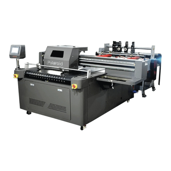
Introduction 1. Printer brief introduction The model of PolaroidHP Single Pass printer is highly cost-effective equipment specially designed for commercial printing enterprises. 2. Printer configurations Model Polaroid SC215 (SC430 SC645 SC860) Printhead type HP heads Printhead array 1/2/3/4 PCS Maximum resolution... -
Page 7: Electrical Description
Electrical description 1. Power Switch 220V 2. Y axis Servo 3. PLC 4. 220V terminal block 5. 24V terminal block 6. 24V terminal block 6. 24V terminal block 7. Ink supply module 8. DC 33V power supply (Head1) 9. DC 33V power supply (Head2) 10. -
Page 10: Heads Installation Instructions
Heads installation instructions This step must be operated by qualified technicians with a view to avoid damage to printhead and integrated circuit, and reduce the risk of unexpected hazard due to improper operations. The connection of printhead cables can only be executed in the state of power-off. The pins of the cables must avoid to be dipped with any liquid and should never be bent. - Page 11 1. Follow the picture instructions to connect the print head cable. 2. Install the heads on the bottom plate, align it at the lower left corner, and lock the pressure block to fix the heads. 3. As shown in the picture, insert the ink inlet tube and the ink return tube. 4.
- Page 12 Horizontal is closed, vertical is open. Ink circulation switch As shown in the picture: closed Horizontal is closed, vertical is open. Ink switch As shown in the picture: closed Turn on one ink switch, and all others are off. Turn on the corresponding ink circulation switch Wait for two minutes, the inside of the nozzle is filled with ink.
-
Page 13: Computer System Configuration
7. Vertical correction The heads are installed for the first time, it needs to be corrected vertically 1) First make a 650 cm black wire frame. 2) Print it out and check where the two nozzles meet. 3) Rotate the nozzle to make the transfer place become a straight line 4) Print the wireframe again and see the result. -
Page 15: Unstable Internet Speed Solution
1.2 Unstable internet speed solution If you find that the network speed is unstable and the packet loss and reconnection rates are high during use, you can do the following: Right-click "This Computer" on the desktop and select "Manage"... - Page 16 Set the "Jumbo Packet" value to 4088Bytes. OK.
-
Page 17: Software Installation
Software Installation Printing software installation Open the U disk Double-click the installation package Follow the instructions step by step (pictured) Change the installation location (where you need it) Tick the number of head of your machine(2500-1H=1 head ;2500-2H=2 head;2500-3H=3 head) Click "yes"... - Page 18 Click "Finish" Double click to open 1.3 Environment installation Double click the installation file Follow the installation instructions to complete the installation.
-
Page 19: Software Interface Description
Software interface description Open: Add a single print file Folder: Add print files for an entire folder Send: The data loaded by ①"Open" is sent to the board for printing through here. The number of print copies can be set at ⑨. Set 0 copies as external photoeye trigger; Pause: Pause print task Stop and reset:... - Page 20 There are 10 groups of one nozzle, from there to the left . (G1 G2 G3 G4 G5 G6 G7 G8 G9 G10) (G11 G12 G13 G14 G15 G16 G17 G17 G19 G20) The even-numbered (G2 G4 G6 G8) printheads remain stationary, and the odd-numbered (G1 G3 G5 G7 G9) printheads are offset by 58 pixels overall, so that each group of printheads can be correctly connected...
- Page 21 7.2 Color base adjust The color registration of the channels between each column in each group of nozzles is based on the unit of the code disk. mm is coarse adjustment, the unit is millimeter, PX is fine adjustment. The unit is the code disk value. For example, make a pixel-wide KCMY four-color black line, and print with eight channels inside each group of nozzles after adjustment.
- Page 22 3. Compare the state diagram of the nozzle to confirm which channel is not well connected. 4. Modify the value of the software corresponding to the two channels, increase (image overlap), decrease (image separation) save (For example 25 becomes 15)...
- Page 23 5. Must be modified in order from G1→G2→G3 (Modify one by one) 6. Print the image again to see the effect of the modification. This better...
- Page 24 7.4 Nozzle distance Adjust the distance between the two nozzles so that the two nozzles just overlap horizontally...
-
Page 25: Advanced Settings
For example, in the picture above, HB00 needs to move downwards and be on the same level as HB01. If it is 3H, 4H, use the middle nozzle as the reference, adjust the left and right nozzles to align with the middle nozzle. Advanced settings:... -
Page 26: Test
Test: Click to load the print head test image. Then print a test to check if the head works well 10. Trigger and Copies Settings Set the conditions that trigger printing, and the number of copies printed by a single task 11. -
Page 27: Touch Screen Instructions
Touch screen instructions 1.1 Home page display 1.2 Print control interface... - Page 28 Control Click to switch the printing It is recommended to use low speed for speed high precision (DPI) and high speed for low (High speed, medium speed, precision (DPI). low speed) Select the set material X and Select Custom to write parameters in X and Z parameters Y below 1.
-
Page 29: Parameter Setting Interface
Other Number of copies that Display the number of prints have been printed. Click on the right box and enter the number of copies to be printed Set the number of copies When the value in Quantity reaches to be printed the set value entered, the machine stops working After clicking the button, the... - Page 30 X axis Running speed X axis movement speed When there is an error between the moving distance of the motor and Motion coefficient the set value, you need to modify the value here to correct Deviation Positioning calibration compensation Maximunm stroke Maximum movable distance of trolley Z axis Running speed...
- Page 31 Engineer Real-time monitoring of ink cartridges Real-time sensor monitoring Currently only supports Click to switch language Chinese, English, Portuguese, Spanish, Italian.
-
Page 32: Material Information
1.4 Material information 1. Fill in the position information set during printing of the printed material. If the same material is printed again next time, it can be called directly. Print job flow Turn on the machine 1. Power on the machine, open the software 2. -
Page 33: Appendix I Feeder
Appendix I: Feeder Move to a suitable location Adjust height, lock(The material is 5mm higher than the equipment platform) Connect cables and signal lines Put the material, adjust the baffles on both sides, clamp the material Raise the tail of the material Adjust the height of the discharge baffle The exit height is higher than 1pc, lower than 2pc... - Page 35 Calle 10 No. 206, Col. Granjas San Antonio Del. Iztapalapa, C.P. 09070 CDMX, México info@polaroidlargeformat.com www.polaroidlargeformat.com...
Need help?
Do you have a question about the SINGLE PASS and is the answer not in the manual?
Questions and answers