
Related Manuals for AEG PROTECT RCS MIPe


Summary of Contents for AEG PROTECT RCS MIPe
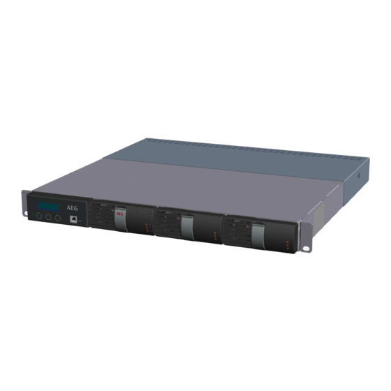
- Page 1 Rectifier, battery charger and PROTECT RCS DC/DC converter rack with CoSSMIC Slot controller Installation and operation manual MIPe Modular Industrial Power 19'' rack 6kW-150A BN 133436/01/01 – 13/03/2024...
- Page 2 AEG Power Solutions is a world specialist in AC and DC power conversion. The company designs and manufactures rectifiers, inverters and power electronics systems associated with all types of batteries. The applications range from Oil & Gas, Petrochemicals, Transport, Power, Manufacturing and Telecommunications Industries through to Military applications.
-
Page 3: Table Of Contents
CONTENTS INTRODUCTION ................4 PRESENTATION OF THE SYSTEM ..........5 2.1 RECTIFIER / CONVERTER POWER RACK ........... 6 2.2 RECTIFIER / CONVERTER MODULE ............. 6 2.3 COSSMIC SLOT CONTROL MODULE ........... 7 INSTALLATION ................8 3.1 HANDLING ....................8 3.2 INSTALLING AND SECURING THE RACK ..........8 3.3 INSTALLING THE BATTERY .............. -
Page 4: Introduction
RCS MIPe range of rectifiers, battery chargers and DC/DC converters delivered as 19 inches racks. To use the system properly, the user should first read this manual carefully. AEG is not be responsible for damage due to improper use, neglect, alterations, or use of other than original parts without our written consent. -
Page 5: Presentation Of The System
2 PRESENTATION OF THE SYSTEM The aim of the 19” rack is to provide a compact and ready to use solution for DC power supply or battery charger solutions. The racks are composed of the following elements: 1. 19’’ compatible rack used a mechanical support and receiving the interface mother board, the CoSSMIC Slot controller and up to 3x rectifier or converter modules 2. -
Page 6: Rectifier / Converter Power Rack
2.1 RECTIFIER / CONVERTER POWER RACK Through its interface mother board, the power rack is designed to receive up to 3x MIPe rectifier or converter modules, and is compatible with the 4 DC nominal voltages 24V, 48V, 110V and 220V. 1. -
Page 7: Cossmic Slot Control Module
WARNING : the mother interface board is not delivered with all the male connectors as standard feature. The user shall purchase himself the missing connectors or buy the AEG optional connector set. NOTE : the battery charger function is only available when rectifier modules are used. When DC/DC converters are used, the system will work as a DC power supply only without battery management function. -
Page 8: Installation
3 INSTALLATION The racks are delivered with all the different parts assembled on a 19’’ compatible mechanical structure. 3.1 HANDLING The equipment and its associated batteries (if applicable) must be handled with care, the electronic boards that are not protected shall not be touched or sustain mechanical constraints nor shocks. CAUTION: - The 19”... -
Page 9: Installing The Battery
CAUTION: Do not touch the internal rack mechanical parts, high temperatures might be present. Make sure that enough space is present above and below the charger rack in order to ensure a proper cooling. Rack mechanical fixing : The front 19’’ fixing plates do not procure a sufficient mechanical robustness, therefore a mechanical support located in the rack depth is mandatory. -
Page 10: Environmental Requirements (Excluding The Battery)
3.4 ENVIRONMENTAL REQUIREMENTS (EXCLUDING THE BATTERY) Storage in standard carboard packing box Temperature: - 25°C to +70°C Relative humidity: 15% to 90% in the original package. Maximum storage period: 3 months. Storage in seaworthy packing Temperature: - 25°C to +70°C Relative humidity: 15% to 90% in the original package. -
Page 11: Mains Input Connection
4.1 MAINS INPUT CONNECTION DANGER, THE RECTIFIER MODULE IS EQUIPPED WITH INPUT FILTERS: MAINS INPUT: HIGH LEAKAGE CURRENT. EARTH CONNECTION IS MANDATORY BEFORE CONNECTING THE MAINS SUPPLY. IF A 3 PHASE MAINS IS SUPPLYING THE RACK, THE NEUTRAL CONNECTION IS MANDATORY It is mandatory to install a mains input protection in the mains switchboard upstream the charger. -
Page 12: Dc Load Connection
4.2 DC LOAD CONNECTION IMPORTANT RECOMMENDATIONS REFER TO THE BATTERY MANUAL. Refer to the battery manufacturer's instructions for the storage conditions. Never short-circuit a battery. Allow no flame nor sparks in the battery room. Never smoke in the battery room. Never disconnect a battery being charged. - Page 13 P105 : DC + output of Rectifier 1 or DC/DC converter 1 P106 : DC - output of Rectifier 1 or DC/DC converter 1 P107 : DC + output of Rectifier 2 & Rectifier 3 or DC/DC converter 2 and 3 P108 : DC - output of Rectifier 2 &...
-
Page 14: Connecting The Options And Alarm Contacts
4.3 CONNECTING THE OPTIONS AND ALARM CONTACTS All the options and the associated functions are connected to the interface mother board as shown hereafter : Option Connector name on Connector/cable type Comment interface mother board Internal CAN bus J103 and J104 RJ4P/4C For extension 19”... -
Page 15: Start-Up (Refer To The Drawing Package)
5 START-UP (REFER TO THE DRAWING PACKAGE) Important notice : the 19” power rack is delivered with generic parameters that might not be adapted to the solution technical features (mains input, DC output voltage, battery type and charging voltages, type of rectifier or converter module …). -
Page 16: Battery Commissioning Charge
To check that the battery polarities are correct, take a voltage reading using a DC voltmeter as shown below: + BATT + BATT - BATT - BATT LOAD LOAD - Case 1 - - Case 2 - Configuration with battery fuse F13 Configuration without opening device The voltage reading must not exceed 30% of the nominal voltage (refer to the customer drawings). -
Page 17: Operating Instructions
6 OPERATING INSTRUCTIONS The following section explains the basic operator menu structure of your system. It allows you to access all necessary functions in order to operate your system. The menus, indications and controls available depend on the system configuration. The keyboard assembly has two LEDs indicators: green LED: CoSSMICSlot controller is powered red LED: steady = URGENT alarm / blinking = NON URGENT alarm... -
Page 18: Human Interface Structure
6.3 HUMAN INTERFACE STRUCTURE The human interface is based on consistency in operation. Consistency means that the functions are grouped logically within the menu structure and will provide ease of use for the operator. The LCD Display has 2 lines by 16 characters. The top line is always used to indicate information while the bottom line is used for the menu structure indication. -
Page 19: Monitoring Functions
6.4 MONITORING FUNCTIONS 6.4.1 Alarm menu Display of the list of the alarms present on the system. Bat : Low Volt EXIT NEXT PREV ● ● ● EXIT : go back to the main menu / NEXT : display of the next alarm in the list / PREV : display the previous alarm in the list Alarm list present on the system and depending on the configuration : Label... - Page 20 6.4.2 System menu Display of the system electrical and physical measurements. Vload : 54.5V EXIT NEXT PREV ● ● ● EXIT : go back to the main menu / NEXT : display of the next value / PREV : go back to the previous value List of the displayed values : Vload : Load output voltage (V)
- Page 21 6.4.4 Converter module menu Display of the converter module group status and information. DC_DC EXIT NEXT ENTER ● ● ● EXIT : go back to the main menu / NEXT : go to the next converter group / ENTER : access to the converter group data.
- Page 22 Communication type declared in the control board SLAVE : Slave number PROT : Communication protocole (AEG PS / MODBUS ASCII ; RTU ; master) IP ADDRESS : IP address (for UART 1 to 2) NET MASK : Net mask information (for UART 1 to 2)
- Page 23 6.4.10 Service counter menu Display of the service counter figures, stored on a memory of the CoSSMIC board, and recoreded over the time of service of the system. Those information can be used for preventive maintenance and can be associated with alarm triggering events.
- Page 24 6.4.12 Date and time menu Display of the date and time of the internal clock of the control board. Those data are used in history loggin process. 22/10/2020 EXIT NEXT PREV ● ● ● EXIT : go back to the main menu / NEXT : display of the next parameter / PREV : go back to the previous value List of the displayed information : 22/10/2020 Date in Day/Month/Year format...
-
Page 25: Configuration Functions
6.5 CONFIGURATION FUNCTIONS The configuration menu is composed of the following menus which allow to change the associated parameters : Batt. Setting Access to battery settings for modification Batt. Float Access to battery floating parameters for modification Batt. Highrate Access to battery high rate parameters for modification Batt. - Page 26 6.5.2 Battery float charge parameter menu Access to the battery float charge parameters for modification. NEXT ● ● ● - : decrease the value / + : increase the value / NEXT : go to the next parameter or in case of parameter change a confirmation message is displayed (OK / CANCEL).
- Page 27 6.5.5 Battery discharge test menu Access to the battery discharge parameters for modification. This test will assess the actual battery capacity, handling a discharge test using dedicated parameters. It can be either automatically triggered with a pre-defined interval, or triggered manually. I Test : 15% NEXT ●...
- Page 28 6.5.7 Power supply menu Access to the power supply parameters for modification. The values entered have an immediate effect on the system output voltage and maximum current when acknowledged, but can’t exceed the system limit values fixed by the control board and calculated from nominal parameters. Vout : 56V NEXT ●...
- Page 29 Date and time : Access to the modification of date (format Day/Month/Year) and time (format Hour/Min/Sec) Note : all the other parameters (system setup, alarm and events setup, calibration) are only accessible through AEG Power Solution dedicated software. BN 133436/01/01 – 13/03/2024...
-
Page 30: Command Functions
6.6 COMMAND FUNCTIONS The command menu is composed of the following menus which allows to change the associated parameters : Rectifier Launch the process to take into account a new configuration of rectifier, rectifier LED test and to trigger a shutdown of the rectfiers. Alarm For alarm acknowledgment and to clear the alarm history Battery charge... - Page 31 6.6.3 Battery charge menu Access to the battery charge commands. Force float EXIT NEXT VALID ● ● ● EXIT : go back to the main menu / NEXT : go to the next menu item / VALID : trigger the selected action List of the parameters accessible to trigger an action : Force float : Force the charger to enter in floating charge (used to stop manually high rate,...
- Page 32 6.6.6 Controller menu Access to the controller parameters commands. Synch. memory EXIT NEXT ENTER ● ● ● EXIT : go back to the main menu / NEXT : go to the next menu item / ENTER : trigger the action displayed List of the parameters accessible to trigger an action : Synch.
-
Page 33: Functional Description
7 FUNCTIONAL DESCRIPTION The MIPe rectifiers and converters are switch mode modules suitable for charging nickel-cadmium or lead-acid batteries while supplying DC loads. The rectifier/converters can be also used without batteries as direct power supplies. 7.1 OPERATING SEQUENCES Example on rectifier with associated battery Mains power ON –... -
Page 34: Charge Modes
7.2 CHARGE MODES The following battery charge modes are available (depending on the equipment): Floating charge Floating charge compensates for the self-discharge of the battery and, in normal operation, maintains the battery in a fully charged condition. High rate charge (or equalizing charge) High rate charge restores the battery to full capacity. -
Page 35: Cossmic Slot" Generic Control And Alarm Unit - Slot (A1)
The mains voltage is applied to the rectifier or converter module input via the upstream circuit-opening devices. The rectifier/converter is then in service, provided no fault has been detected and/or stored by the monitoring systems. The AC/DC rectifies the mains voltage (or the DC/DC module converts the DC input voltage into a DC output voltage). -
Page 36: Options
8 OPTIONS The equipment has these options fitted only if they have been specified in the initial order. Refer to the customer drawings. 8.1 ALARM/SIGNALLING/MEASUREMENT OPTIONS 8.1.1 LED box (A6) The front door of the rectifier can be equipped with 16 electroluminescent diodes and related texts. The LEDs indicate alarm or events as configured in the CoSSMIC Slot board. -
Page 37: Communication Options
8.1.4 Ground fault detection 1 - Case of a single MIPe rectifier The option is integrated into the CoSSMIC board. The ground fault detection circuit monitors the impedance of the connection between ground and the positive and negative polarities of the DC output. An alarm is delivered on detection of a leakage current ≈... - Page 38 ASCII format. This provides the ability to control/monitor several types of equipment (external meters, inverters, etc…) Contact your AEG reseller for details. 8.2.5 TCP/IP Communication This option includes a NCS board connected to A71 (RS232 board) and allowing TCP/IP communication with the CoSSMIC Slot control board.
-
Page 39: Control/Command Options
Please contact AEG Power Solutions Service Department for more details. • Factory: this 4 level allows to change all the parameters in the system. This level is reserved to AEG Power Systems staff.. 8.3 CONTROL/COMMAND OPTIONS 8.3.1 Manual voltage and/or current adjustments... -
Page 40: Load Options
8.3.4 Remote high rate charge This option is used to put the rectifier in high rate charge via a normally open (NO) contact from remote control panel. The option uses one spare input . 8.3.5 Remote fan control room & remote forced floating charge This combined remote option allows to control the ventilation of the battery room for air renewal. - Page 41 8.5.3 Cable drop compensation The rectifiers can be programmed (cable drop parameter) to compensate for cable drop between the system and the battery without the need of remote sensing. If battery current limit/display option is present: The output voltage will be increased as a function of the battery recharge current. If battery current limit/display option is not present: The output voltage will be increased as a function of the load current.
- Page 42 The time needed to reach the End Voltage level is compared to the time of the previous battery test. This previous time is multiplied with a tolerance factor to compensate for battery performance. If the time is shorter than this reference time, an alarm “BATT.TEST FAILED”...
-
Page 43: Rack Options
8.6 RACK OPTIONS 8.6.1 Connector set for mother interface board In order to connect the wires to the optional functions, connectors need to be added on the interface board. This set supplies all the missing connector in order to make accessible all the connection points. This set does not contain the DC output power connection bus bars included in cover option. -
Page 44: Maintenance
9 MAINTENANCE AEG Power Solutions can provide a Global Service capability through regional Service Centres. Electronic boards are sensitive to E.S.D. (electrostatic discharge). When not installed in the equipment, they are delivered in antistatic bags. -
Page 45: Fan Maintenance
9.1.2 Battery maintenance For the recommended battery maintenance procedures, refer to the battery manufacturer’s manual. At the end of their service life, the batteries must be recycled in compliance with the European Directive n° 91/157/EEC of 18.03.91 and WEEE directive. You can also apply to the battery manufacturer as indicated in the battery manual. - Page 46 ALARM or EVENT PROBABLE CAUSE CORRECTIVE ACTION BATT VOLT HIGH The rectifier output voltage is higher than . Call the Customer Service the maximum allowable value. Department. Programmable threshold: default value or customer demand value. BATT VOLT LOW Battery in discharge resulting from: .
- Page 47 ALARM or EVENT PROBABLE CAUSE CORRECTIVE ACTION DISCH TEST FAIL Appears after a battery test. . Call the customer service department BATT CONN TEST . Battery blackout. . Battery in end of life. . Battery not connected BATT ON DISCH Battery in discharge resulting from: .
- Page 48 AEG PS – Technical data in this document does not contain any binding guarantees or warranties. Content only serves for information purposes and can be modified at any time. We will make binding commitments only upon receipt of concrete enquiries and customer notification of the relevant conditions. Due to the non-binding nature of these terms, we assume liability neither for the accuracy nor...
Need help?
Do you have a question about the PROTECT RCS MIPe and is the answer not in the manual?
Questions and answers