Page 1
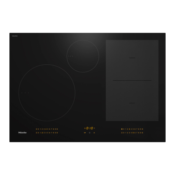
Operating and Installation Instructions Induction Cooktops It is essential to read the operating and installation instructions be- fore setup, installation, and commissioning. This prevents both per- sonal injury and damage to the appliance. en-US, CA M.-Nr. 12 161 430...
Cleaning the cooktop for the first time..............36 Switching on the cooktop for the first time ............36 Miele@home ......................37 Installing the Miele app .................. 37 Setting up Miele@home ................. 37 Establishing a direct connection with the ventilation hood......... 41...
Page 3
Contents Operation......................43 Safety notes for operation ................... 43 Switching the cooktop on ................... 44 Switching off a cooking zone/the cooktop............44 Positioning cookware ..................44 Power level ......................46 Setting the power level................... 46 Setting the power level – extended power level range........46 Changing the power level................
Page 4
Contents Cooktop data ...................... 54 Displaying the model identifier/serial number ..........54 Displaying the software version ..............54 Activating/deactivating demo mode ..............54 Setting ranges....................55 Good to know ....................56 How induction cooktops work ................56 Noises........................56 Cookware ......................57 Customizing settings ..................
Page 5
Contents Declaration of conformity ..................90...
“Installation”, as well as in the “IMPORTANT SAFETY INSTRUCTIONS”. Miele cannot be held liable for injury or damage caused by non- compliance with these instructions. Keep these instructions in a safe place and pass them on to any future owner.
Page 7
IMPORTANT SAFETY INSTRUCTIONS Safety with children Do not leave children unattended: Children should not be alone or unsupervised in the area where the appliance is installed. Do not al- low them to sit or stand on the appliance. Be sure to supervise any children in the vicinity of the cooktop, and do not let them play with it.
Page 8
Unauthorized installation, maintenance, and repairs can cause considerable danger for the user. Installation, maintenance, and re- pairs must only be carried out by a Miele authorized technician. Damage to the cooktop can compromise your safety. Check the cooktop for visible signs of damage. Do not use the cooktop if it is damaged.
Page 9
Do not open the casing of the cooktop under any circumstances. Any repairs not performed by a Miele authorized service techni- cian will void the warranty. Defective components should be replaced by Miele original parts only.
Page 10
Switch it off immediately. Disconnect the cooktop from the electrical power supply. Contact Miele Service. If the cooktop is installed behind a cabinet door, do not close the door while the cooktop is in operation.
Page 11
IMPORTANT SAFETY INSTRUCTIONS Correct use The cooktop gets hot when in use and remains hot for a while af- ter being turned off. There is a potential hazard until the residual heat indicator goes out. Never leave the appliance unattended at high heat settings – Boilover causes smoking and greasy spillovers that may ignite.
Page 12
IMPORTANT SAFETY INSTRUCTIONS If the cooktop is turned on or accidentally turned on or if it is still hot, metal objects on the cooktop can heat up. Other items may melt or catch fire. Damp lids can become attached to the cooktop by suction.
Page 13
IMPORTANT SAFETY INSTRUCTIONS Pots and pans with bases with pronounced edges or ridges can scratch the ceramic surface. Only use pots and pans with smooth bases. Lift pans into position on the cooktop. Sliding them into place can cause scuffs and scratches.
Page 14
IMPORTANT SAFETY INSTRUCTIONS Do not use 2 items of cookware on a cooking zone or extended zone at the same time. If the cookware only partially covers a cooking zone, the handle could become very hot. Always place cookware in the middle of the cooking zone. ...
Page 15
IMPORTANT SAFETY INSTRUCTIONS Cleaning and maintenance Do not use a steam cleaner to clean the cooktop. The steam may reach electrical components and cause a short cir- cuit.
They have been designed to be biodegradable and recyclable. Consult with local authorities, dealers or Miele in order to dispose of and recycle Ensure that any plastic wrappings, electrical and electronic appliances. bags, etc. are disposed of safely and Miele assumes no responsibility for kept out of the reach of children.
Overview Cooktop KM 7735 FL a Cooking zone with TwinBooster b Cooking zone with TwinBooster c PowerFlex cooking zone with TwinBooster can be combined with PowerFlex cooking zone to form PowerFlex cooking area d PowerFlex cooking zone with TwinBooster e Controls and indicators...
Page 18
Overview KM 7745 FL a PowerFlex cooking zone with TwinBooster b PowerFlex cooking zone with TwinBooster can be combined with PowerFlex cooking zone to form PowerFlex cooking area c PowerFlex cooking zone with TwinBooster can be combined with PowerFlex cooking zone to form PowerFlex cooking area d PowerFlex cooking zone with TwinBooster can be combined with PowerFlex cooking zone ...
Page 19
Overview KM 7755 FL a PowerFlex cooking zone with TwinBooster b PowerFlex cooking zone with TwinBooster can be combined with PowerFlex cooking zone to form PowerFlex cooking area c Cooking zone with TwinBooster d PowerFlex cooking zone with TwinBooster can be combined with PowerFlex cooking zone to form PowerFlex cooking area e PowerFlex cooking zone with TwinBooster f Controls and indicators...
Overview Controls and display a Stop & Go sensor control For stopping/starting a cooking process in progress b Cooktop On/Off sensor control c Wipe protection sensor control For locking the sensor controls d PowerFlex cooking zones sensor control For manual connection/disconnection of PowerFlex cooking zones e Keeping warm sensor control For activating/deactivating the Keeping warm function f Numerical display sensor controls...
Overview Cooking zone data KM 7735 FL Cooking Max. rating Linked cooking Size zone in watts for 208 V zone Ø Normal 2,400 7"–11" – TwinBooster, level 1 2,750 (18–28 cm) TwinBooster, level 2 3,350 Normal 1,300 4"–6 1/2" –...
Page 22
Overview KM 7735 FL Cooking Max. rating Linked cooking Size zone in watts for 240 V zone Ø Normal 2,600 7"–11" – TwinBooster, level 1 3,000 (18–28 cm) TwinBooster, level 2 3,700 Normal 1,400 4"–6 1/2" – TwinBooster, level 1 1,700 (10–16 cm) TwinBooster, level 2...
Page 23
Overview KM 7745 FL Cooking Max. rating Linked cooking Size zone in watts for 208 V zone Ø 5 7/8" x 5 7/8" (15 x 15 cm) Normal 1,900 5 7/8"–9" – TwinBooster, level 1 2,750 (15-23 cm) 9" x 7 1/2" TwinBooster, level 2 3,350 (23 x 19 cm)
Page 24
Overview Cookware with a base diameter/surface (width x depth) within the given range may be used. The power indicated may vary depending on the size and material of the cookware used. The cooking zone is linked to this cooking zone electrically so that the rating can be increased; see “Overview –...
Page 25
Overview KM 7745 FL Cooking Max. rating Linked cooking Size zone in watts for 240 V zone Ø 5 7/8" x 5 7/8" (15 x 15 cm) Normal 2,100 5 7/8"–9" – TwinBooster, level 1 3,000 (15-23 cm) 9" x 7 1/2" TwinBooster, level 2 3,700 (23 x 19 cm)
Page 26
Overview Cookware with a base diameter/surface (width x depth) within the given range may be used. The power indicated may vary depending on the size and material of the cookware used. The cooking zone is linked to this cooking zone electrically so that the rating can be increased; see “Overview –...
Page 27
Overview KM 7755 FL Cooking Max. rating Linked cooking Size zone in watts for 208 V zone Ø 5 7/8" x 5 7/8" (15 x 15 cm) Normal 1,900 5 7/8"–9" – TwinBooster, level 1 2,750 (15-23 cm) 9" x 7 1/2" TwinBooster, level 2 3,350 (23 x 19 cm)
Page 28
Overview KM 7755 FL Cooking Max. rating Linked cooking Size zone in watts for 240 V zone Ø 5 7/8" x 5 7/8" (15 x 15 cm) Normal 2,100 5 7/8"–9" – TwinBooster, level 1 3,000 (15-23 cm) 9" x 7 1/2" TwinBooster, level 2 3,700 (23 x 19 cm)
Overview Effects of power distribution Power management system If a cooking zone gives power to an- Total power other zone, this can have the following The cooktop has a maximum total per- effects on the zone giving the power: mitted power consumption which can- - The power level is reduced.
Overview Operation Cooktop when switched off When the cooktop is switched off, you can only see the printed symbols for the sensor controls and the numerical dis- play. More sensor controls light up when the cooktop is switched on. Operation a Sensor controls and indicators This glass-ceramic cooktop is equipped with sensor controls which react to fin-...
- control a connected Miele ventilation hood automatically via the cooktop Miele@home settings (Con@ctivity 3.0) After installing the Miele app on a mo- bile device, you can do the following: - call up information on the operating status of your cooktop...
Con@ctivity 3.0 is the direct communi- quantities can be heated up quickly, cation system between your cooktop e.g., when boiling water for cooking and a Miele ventilation hood. Communi- pasta. cation is achieved by means of net- Stop & Go working. Con@ctivity 3.0 enables the ventilation hood to operate automati- When Stop & Go is activated, all power...
Overview Kitchen timer Residual heat indicator You can set a timer for activities that are If a cooking zone is still hot, the residual independent of the cooktop. heat indicator will light up after it has been switched off. Depending on the Safety shut-off temperature, a dot will appear above power levels 1, 2, and 3.
Overview Safety shut-off Power level* Maximum operating time [h:min] Sensor controls are covered Safety setting Your cooktop will turn off automatically if one or several of the sensor controls 10:00 8:00 5:00 remain covered for longer than 10 sec- onds; for example, by finger contact, 10:00 7:00 4:00...
Overview Overheating protection Triggering the overheating protection mechanism In order to prevent the cooktop from being damaged by excessive tempera- The overheating protection may be acti- tures, the overheating protection mech- vated under the following circum- anism intervenes in one of the following stances: ways: - The cookware being heated is empty.
Commissioning Unpacking the cooktop Switching on the cooktop for the first time Please stick the extra data plate for the appliance supplied with this doc- The metal components have a protec- umentation in the space provided in tive coating. When the cooktop is used the “Customer Service”...
The WiFi connection shares a frequency Installing the Miele app range with other appliances (including The ability to use the Miele app de- microwave ovens and remote control pends on the availability of the toys). This can give rise to sporadic or Miele@home service in your country.
Page 38
The seconds can be seen counting ventilation hood (Con@ctivity 3.0). down in the timer display. After this time has elapsed, the code : is displayed - The Miele app is installed on your in the timer display for 10 seconds. device. You now have 10 minutes to configure the WiFi.
Page 39
The seconds can be seen counting - There is no direct Wi-Fi connection down in the timer display. After the time between the cooktop and a Miele has elapsed, a progress light appears in ventilation hood (Con@ctivity 3.0). the timer display during the connection - You must have a WPS (Wi-Fi pro- attempt (for max.
Page 40
Commissioning Canceling the process Touch any sensor control. Resetting settings Reset the settings if you are disposing of your cooktop, selling it, or putting a used cooktop into operation. This is the only way to ensure that all personal data has been removed and the previ- ous owner will no longer be able to ac- cess the cooktop.
Availability of the Wi-Fi connection The Wi-Fi connection shares a fre- - Miele ventilation hood with quency range with other appliances (in- Con@ctivity 3.0 cluding microwave ovens and remote - The cooktop is not connected to control toys).
Page 42
Commissioning Canceling the process Touch any sensor control. Resetting settings Reset the settings if you are disposing of your cooktop, selling it, or putting a used cooktop into operation. This is the only way to ensure that all personal data has been removed and the previ- ous owner will no longer be able to ac- cess the cooktop.
Operation Safety notes for operation Fire hazard due to overheated food. Unattended food can overheat and ignite. Do not leave the cooktop unattended while it is being used. Risk of burning or scalding due to hot cooking zones. The cooking zones will be hot after use.
Operation Switching the cooktop on Positioning cookware Touch the sensor control. Refer to the cooking zone data for your cooktop model for information about Additional sensor controls will light up. cookware sizes and the corresponding positions (see “Overview – Cooking If no further entry is made, the cook- zone data”).
Page 45
Operation PowerFlex cooking area PowerFlex cooking area...
Operation Changing the power level Power level Touch the appropriate sensor control Setting the power level for the power level you want on the Permanent pan recognition is activated numerical display. as standard (see “Customizing set- Manually switching PowerFlex tings”).
Operation TwinBooster level 2 Booster Place the cookware on the cooking Activating the Booster function zone you want to use. When the Booster function is activated, Select a power level, if necessary. the settings for the linked cooking zone may be changed (see “Overview –...
Operation Activating Auto heat-up Auto heat-up Touch the sensor control for the con- The heat-up time depends on which tinued cooking level you want until a continued cooking level has been cho- tone sounds and the sensor control sen: starts to pulsate.
Operation Setting the kitchen timer Timer Touch the sensor control. Setting timer durations The timer display flashes. A duration of between 1 minute (:) and 9 hours 59 minutes (:) can be Set the required duration (see “Timer set. – Setting timer durations”). Durations of up to 59 minutes are Touch the sensor control or wait shown in minutes (00:59) and durations...
Operation Setting the switch-off time Deleting the switch-off time Touch the sensor control repeat- A cooking zone will switch off when the maximum operating time has elapsed, edly until the indicator light for the independently of a set switch-off time cooking zone you require pulsates.
Operation Using both timer functions at the same time If you use both functions simultane- ously, the shortest time is always dis- played. The sensor control (kitchen timer) or the indicator light of the cook- ing zone with the shortest switch-off time pulsates.
Operation System lock Safety lock Activating the system lock Activating the safety lock When the safety lock is activated: All sensor controls are locked. A set kitchen timer will continue to count - the cooking zones and the cooktop down. can only be switched off - a set kitchen timer can be modified ...
Operation Keeping warm Wipe protection Activating/deactivating the Keeping Activating wipe protection warm function Touch the sensor control. The Keeping warm function cannot be The time counts down in the timer dis- used to reheat food that has gone cold. play.
Operation Cooktop data Activating/deactivating demo mode Displaying the model identifier/serial Switch the cooktop on. number Press the 0 sensor control on any nu- There must not be any cookware on merical display. the cooktop. Press the 0 and 2 sensor controls on ...
Setting ranges The cooktop is programmed with 9 power levels at the factory. If you wish to fine- tune a setting, you can extend the power level range to 17 power levels (see “Cus- tomizing settings”). Setting range Extended set- ting (17 power lev- els) Melting butter, chocolate, etc.
Good to know How induction cooktops work Noises An induction coil is located under each When you use induction cooking zones, cooking zone. The coil creates a mag- the following noises may occur, de- netic field that reacts directly with the pending on the type and shape of the base of the pan and heats it up.
Good to know Unsuitable cookware Cookware - Stainless steel without a magnetic Suitable cookware base - stainless steel with a magnetic base - Aluminum or copper - enameled steel - Glass, ceramics, earthenware, - cast iron stoneware The composition of the pan base can Testing cookware affect the evenness of the cooking re- To test whether a pot or pan is suitable...
Page 58
Good to know Cookware tips - Please note that the pot or pan diam- eter quoted by manufacturers often - Position the cookware as centrally as refers to the maximum diameter or di- possible on the relevant cooking ameter of the top rim. The diameter of zone/cooking area.
Customizing settings Accessing programming mode Setting the program The sensor control is located ap- For a two-digit program number you prox. 1/2" (1 cm) (index finger width) to first need to set the tens position. the left of the sensor control. ...
Page 60
Customizing settings Settings Program Code P:01 Demo mode C:00 Demo mode off C:01 Demo mode on P:03 Factory default C:00 Do not restore factory default set- tings C:01 Restore factory default settings P:04 Power level setting range C:00 9 power levels + Booster C:01 17 power levels + Booster P:06...
Page 61
C:03 Connection possible via WPS push button C:04 WiFi reset to default ( C:00 C:05 Direct WiFi connection of cooktop and ventilation hood without Miele app (Con@ctivity 3.0) P:12 Sensor controls reaction speed C:00 Slow C:01 Normal C:02 Fast...
Page 62
Customizing settings Settings Program Code P:25 Keeping warm temperature C:00 120°F (50°C) 130°F (55°C) C:01 C:02 140°F (60°C) 150°F (65°C) C:03 C:04 160°F (70°C) 170°F (75°C) C:05 C:06 175°F (80°C) 185°F (85°C) C:07 C:08 195°F (90°C) Programs not shown here have no allocation. The factory default setting is shown in bold.
Cleaning and care Safety notes on cleaning and care Danger of burning due to hot surfaces. All parts of the cooktop may be hot after use. Turn off the cooktop. Allow the cooktop to cool down before cleaning it. All surfaces could be discolored or damaged if unsuitable cleaning agents are used or if residues from suitable cleaning agents are heated on the cooktop.
Page 64
- eraser sponges Clean the glass ceramic surface with - sponges the Miele ceramic and stainless steel cleaner (see “Optional accessories – Cleaning and care products”) or with a proprietary ceramic glass cleaner. Please follow the cleaning-agent manufacturer’s instructions.
You can save time and money in many cases, as you do not need to contact Miele Customer Service. Information to help you rectify faults yourself can be found at www.miele.com/service. The following tables are designed to help you to find the cause of a malfunction or a fault and to resolve it.
Page 66
Make sure it has not been blocked by an object. the timer display. Remove the obstruction. If this fault message continues to appear in the display, contact Miele Customer Service. In the timer display, an The fan is blocked or defective. E-number such as E-0 ...
Frequently asked questions Unexpected behavior Problem Possible cause and solution The symbol lights up No cookware is present on the cooking zone. or flashes alternately Unsuitable cookware is present on the cooking zone. with the set power level The base diameter of the cookware used is too small. or ...
Page 68
Frequently asked questions Problem Possible cause and solution The Booster level has Overheating protection has been triggered. automatically turned off Allow the cooktop to cool down. early. Rectify the causes of the overheating (see “Over- view – Overheating protection”). ...
Check if the breaker has tripped. Contact a quali- switched on. fied electrician or Miele Customer Service (for the minimum fuse rating, see the data plate). There may be a technical fault. Disconnect the cooktop from the electricity supply for approx.
Customer Service Information to help you rectify faults yourself and about Miele spare parts can be found at www.miele.com/service. Contact in the event of a fault In the event of a fault which you cannot remedy yourself, please contact your Miele dealer or Miele Customer Service.
Optional accessories Miele offers a range of useful acces- Cleaning and care products sories, as well as cleaning and condi- Ceramic and stainless steel cleaner tioning products for your appliance. 250 mL These products can be easily ordered Removes heavy soiling, lime scale, and from the Miele webshop.
*INSTALLATION* Installation Safety notes for installation Risk of damage caused by incorrect installation. Incorrect installation can damage the cooktop. The cooktop must only be installed by a qualified specialist. Risk of electric shock from voltage. Incorrect connection to the power supply may result in an electric shock.
Page 73
*INSTALLATION* Installation After the installation of the cooktop, the electrical cord may not come into contact with any moving kitchen parts (e.g. a drawer) or be subject to mechanical stress. The countertop must be heat-resistant (up to 212°F / 100°C), so that it does not become deformed or the veneer detached.
*INSTALLATION* Installation Additional safety notes for proud installation Damage caused by incorrect installation. Using sealant under the cooktop could result in damage to the cooktop and the countertop if the cooktop ever needs to be re- moved for servicing. Do not use sealant between the cooktop and the countertop.
*INSTALLATION* Installation Additional safety notes for flush installation Damage caused by unsuitable sealant. Unsuitable sealant can damage natural stone. For natural-stone countertops and natural-stone tiles, only use sili- cone sealant that is specially formulated for natural stone. Please follow the manufacturer’s instructions. ...
*INSTALLATION* Installation Safety distances Safety distance above the cooktop She safety distance specified by the manufacturer of the ventilation hood must be maintained between the cook- top and the ventilation hood above it. When two or more appliances which have different safety distances are in- stalled together below a ventilation hood, you should observe the greatest safety distance.
Page 77
*INSTALLATION* Installation Safety distance behind and to the side of the cooktop The minimum safety distances shown below must be maintained between the appliance and a tall cabinet or wall: - between the back of the counter- top cut-out and the rear edge of the countertop: 2"...
Page 78
To ensure sufficient ventilation to the cooktop, a minimum safety distance must be left between the underside of the cooktop and any oven, protective base, or drawer. The minimum safety distance KM 7735 FL, KM between the underside of the KM 7745 FL 7755 FL...
Page 79
*INSTALLATION* Installation Safety distance from the wall covering If a wall covering is installed, a minimum safety distance must be maintained be- tween the countertop cut-out and the covering. High temperatures can alter or damage these materials. Flush installation Proud installation a Wall frame b Dimension x = thickness of the wall covering material c Countertop...
*INSTALLATION* Installation Building-in dimensions for proud installation KM 7735 FL All dimensions are given in mm and inches. The superscript numbers after the cut-out di- mensions are the tolerances for the cut-out. a Front b Flexible metal hose with power cords, L = 4' (1,200 mm)
Page 81
*INSTALLATION* Installation KM 7745 FL All dimensions are given in mm and inches. The superscript numbers after the cut-out di- mensions are the tolerances for the cut-out. a Front b Flexible metal hose with power cords, L = 4' (1,200 mm) c Spacer plate (only required if a protective base is installed)
Page 82
*INSTALLATION* Installation KM 7755 FL All dimensions are given in mm and inches. The superscript numbers after the cut-out di- mensions are the tolerances for the cut-out. a Front b Flexible metal hose with power cords, L = 4' (1,200 mm)
*INSTALLATION* Installation Installation dimensions for flush installation KM 7735 FL All dimensions are given in mm and inches. The superscript numbers after the cut-out di- mensions are the tolerances for the cut-out. a Front b Flexible metal hose with power cords, L = 4' (1,200 mm) c Stepped cut-out, natural stone countertop d Wooden strip 1/2"...
Page 84
*INSTALLATION* Installation KM 7745 FL All dimensions are given in mm and inches. The superscript numbers after the cut-out di- mensions are the tolerances for the cut-out. a Front b Flexible metal hose with power cords, L = 4' (1,200 mm) c Spacer plate (only required if a protective base is installed) d Stepped cut-out, natural stone countertop e Wooden strip 1/2"...
Page 85
*INSTALLATION* Installation KM 7755 FL All dimensions are given in mm and inches. The superscript numbers after the cut-out di- mensions are the tolerances for the cut-out. a Front b Flexible metal hose with power cords, L = 4' (1,200 mm) c Stepped cut-out, natural stone countertop d Wooden strip 1/2"...
*INSTALLATION* Installation Place the cooktop centrally in the Installing a proud cooktop cut-out. When doing this, make sure Create the countertop cut-out. Re- that the seal of the appliance sits member to maintain the minimum flush with the countertop on all sides. safety distances (see “Installation –...
*INSTALLATION* Installation If an air intake-optimized base panel Installing the cooktop flush is installed, position the cooktop so with the countertop that the fans are located above the Create the countertop cut-out. Re- cut-outs. member to maintain the minimum ...
It is impera- Miele cannot be held liable for any tive that this basic safety require- damage arising as a result of such ment be met. If there is any doubt, work.
Page 89
*INSTALLATION* Installation Connection Make sure that the power outlet is ac- cessible after the installation of the ap- Ensure that the connection data on pliance. the data plate (voltage, frequency, and fuse rating) match those of your Further information can be found on the electrical supply.
Page 90
*INSTALLATION* Installation Declaration of conformity Supplier's Declaration of Conformity 47 CFR § 2.1077 Compliance Informa- tion Induction Cooktop Unique Identifier: Miele Model: KM7735; KM7745; KM7755 Responsible Party Miele, Inc. National Headquarters 9 Independence Way Princeton, NJ 08540 Phone: 800-843-7232 Fax: 609-419-4298 www.mieleusa.com FCC Compliance Statement: This device complies with Part 18 of the FCC Rules.
Page 91
*INSTALLATION* Installation Warning! Any changes or modifications to this unit not expressly approved by the party responsible for compliance could void the user’s authority to operate the equip- ment.
Page 95
Customer Service. U.S.A. Canada Miele, Inc. Importer Miele Limited National Headquarters Headquarters and Miele Centre 9 Independence Way 161 Four Valley Drive Princeton, NJ 08540 www.mieleusa.com Vaughan, ON L4K 4V8 www.miele.ca Customer Support Phone: 888-99-MIELE (64353) Customer Care Centre info@mieleusa.com...
Page 96
KM 7735 FL, KM 7745 FL, KM 7755 FL en-US, CA M.-Nr. 12 161 430 / 00...
Need help?
Do you have a question about the KM 7735 FL and is the answer not in the manual?
Questions and answers