Table of Contents
Advertisement
Advertisement
Table of Contents

Related Manuals for Asus ROG Strix G15DK


Summary of Contents for Asus ROG Strix G15DK
- Page 1 Desktop ROG Strix (G15DK) Service Manual...
- Page 2 INCIDENTAL, OR CONSEQUENTIAL DAMAGES (INCLUDING DAMAGES FOR LOSS OF PROFITS, LOSS OF BUSINESS, LOSS OF USE OR DATA, INTERRUPTION OF BUSINESS AND THE LIKE), EVEN IF ASUS HAS BEEN ADVISED OF THE POSSIBILITY OF SUCH DAMAGES ARISING FROM ANY DEFECT OR ERROR INTHIS MANUAL OR PRODUCT.
- Page 3 ASUS will only be responsible for or indemnify you for loss, damages or claims based in contract, tort or infringement under this Warranty Statement. This limit also applies to ASUS' suppliers and its reseller. It is the maximum for which ASUS, its suppliers, and your reseller are collectively responsible.
- Page 4 Disclaimer ASUS is not responsible for direct, indirect, intentional or unintentional damages resulting from improper installation and operation. Safety precautions • Before handling components, use a grounded wrist strap or touch a safely grounded object to avoid damaging them due to static electricity.
-
Page 5: Table Of Contents
Table of Contents ⚫ ASUS Desktop ROG strix G15DK Overview ⚫ Components Top View ⚫ Components Bottom View ⚫ Components top View (For Glass version) ⚫ Appropriate Tools ⚫ Disassembly steps : • SLIDE DOOR • VGA CARD • DDR & SSD CARD •... -
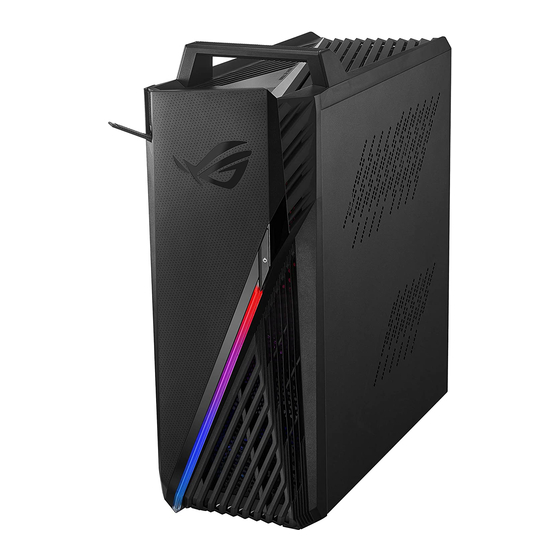
Page 6: Asus Desktop Rog Strix G15Dk Overview
ASUS Desktop ROG strix G15DK Overview Front & Top View Rear Panel View ❶ Power button ❶ PS/2 keyboard/mouse combo port ❷ Headphone port ❷ USB 3.2 Gen 1 ports ❸ Microphone port ❸ DVI-D port ❹ USB 3.2 Gen 1 Type-C® port ❹... -
Page 7: Components Top View
Components Top View ♦ VGA Card ♦ D700TA M2 ♦ LED CR BD ♦ HDD SATA CABLE ♦ POWER SW CABLE ♦ D640MB STAND OFF ♦ ♦ VRM HS SUP BKT PAD 25X20X7 M2*4.6H*4.75D GA15DH_PSU_GASKET ♦ DDR ♦ FAN ♦ GA15DH FRONT ♦... -
Page 8: Components Bottom View
Components Bottom View ♦ VGA Card ♦ FAN ♦ MB PLATE AL FOIL ♦ DDR ♦ MAIN BOARD ♦ CPU SOCKET ♦ ♦ WIFI CARD ♦ LED CR BD ♦ M.2 SSD ♦ FRONT IO BD Back... -
Page 9: Components Top View (For Glass Version)
Components top View (For Glass version) ♦ HDD SCREW MYLAR ♦ MID BKT ♦ GA15DH TOP LED BD ASSY ♦ VRM ♦ GA15DH SIDE LED BD SINK Tighten HDD screws and paste the Mylar on the case when assembling. ♦ GA35DX GLASS DOOR ASSY ♦... -
Page 10: Appropriate Tools
Appropriate Tools Please prepare and select the appropriate tools to disassemble/assemble for the ROG Strix (G15DK) desktop. ♦ Screwdriver ♦ Alcohol 95% ♦ Glove ♦ Dust-free Cloth Please accord to different screw specification to choose different screwdriver and head. #1 #2 ♦... -
Page 11: Slide Door
SLIDE DOOR Disassembly Notice Please be sure to pull out adapter and disconnect the battery. Step 1 : Remove screws *4pcs. Screws Spec Torque (kgf-cm) Step 2 : Pull the side doors*2pcs. SCREW #6-32 L6*H2.3 (B)B-NI-ZN 8.0± 0.5 Pull SLIDE DOOR (L) Pull SLIDE DOOR (R) Back... -
Page 12: Vga Card
VGA CARD Disassembly Notice Please be sure to pull out adapter and disconnect the battery. Step 1 : Remove screws *2pcs. Screws Spec Torque(kgf-cm) Step 2 : Press and unlock the VGA card. SCREW #6-32*L6 (B)B-NI-ZN NY 4.0± 0.5 Step 3 : Take out the VGA card. Press Back... -
Page 13: Ddr & Ssd Card
DDR & SSD CARD Disassembly Notice Please be sure to pull out adapter and disconnect the battery. Screws Spec Torque (kgf-cm) Step 1 : Unlock then remove DDR *2pcs. Step 2 : Remove screw *1pcs then take out the SSD *1pcs. M2*3L(4.6,0.8) (K)#1 2.0 ±... -
Page 14: Wifi Card & M.2 Wifi Card
WIFI CARD & M.2 WIFI CARD Disassembly Notice Please be sure to pull out adapter and disconnect the battery. Step 1 : Disconnect the RF CABLE (connectors)*2pcs. Screws Spec Torque (kgf-cm) Step 2 : Remove the screw *1pcs. Step 3 : Remove WIFI CARD. M2*3L(4.6,0.8) (K)#1 2.0±... -
Page 15: Fan
Disassembly Notice Please be sure to pull out adapter and disconnect the battery. Step 1 : Disconnect (yellow mark) FAN connector *1pcs. Screws Spec Torque (kgf-cm) Step 2 : Remove 4 screws on the outside of iron grid. M5*10L (F) W-NI (TP5) 8.0±... -
Page 16: Main Board With Cpu Cooler & Cpu
MAIN BOARD with CPU COOLER & CPU Disassembly Notice Please be sure to pull out adapter and disconnect the battery. Step 1 : Disconnect (yellow mark) connectors *8pcs. Screws Spec Torque (kgf-cm) Step 2 : Remove screws *8pcs (Red and green mark). Step 3 : Take out the Main Board. - Page 17 MAIN BOARD with CPU COOLER & CPU CPU COOLER Disassembly Notice Assembly Notice If the CPU COOLER is hard to disassemble, Please follow the instructions to assemble the CPU. please move the COOLER left and right to separate CPU triangle must be aligned to MB triangle Pin facing down on Processor packaging to protect the Please follow the instructions to assemble MAIN BOARD.
- Page 18 MAIN BOARD with CPU COOLER & CPU Assembly Notice Please be sure to pull out adapter and disconnect the battery. Please make sure that re-smear thermal material on CPU Die, if thermal module have to be reassembled. Step-1 : Using dust-free cloth with 95% alcohol to clean up the residual thermal grease on CPU& GPU Die. Step-2 : Please use plastic tool (Plastic stick) to get Thermal Grease, and smear over CPU around 0.2~0.3mm thick.
-
Page 19: Front Cover And Led Board
FRONT COVER AND LED BOARD Disassembly Notice Please be sure to pull out adapter and disconnect the battery. Step 1 : Tear the CABLE CONDUCTIVE CLOTH and loose the POWER SW CABLE. Screws Spec Torque (kgf-cm) Step 2 : Pull the latch slightly away. M2.5*5L (4.6,1.7) (P) #1 3.0±... -
Page 20: Power Switch
POWER SWITCH Disassembly Notice Please be sure to pull out AC POWER CORD. Assembly Notice Please follow the steps below to assemble POWER SWITCH HOLDER and Step 1 : remove POWER SWITCH HOLDER with POWER SW CABLE from front case. Step 2 : Release hooks (green mark) then take out POWER SW CABLE from POWER SWITCH HOLDER. - Page 21 FRONT BEZEL ASSY FRONT BEZEL Assembly Notice NOTE! Before assembling the FRONT BEZEL ASSY, please carefully read the following assembly instructions . When assembling the LED board, USB cable and power cord on the FRONT BEZEL ASSY, please make sure that the USB cable and power cord do not touch the PIN HEADER of the LED board, otherwise it may cause a short circuit and overheating.
- Page 22 FRONT BEZEL ASSY FRONT BEZEL Assembly Notice Step-3 After connecting the POWER and USB cable to the LED board, please tidy up the cables in the direction of the yellow arrow and be careful to avoid the PIN HEADER (marked in red). PIN HEADER PIN HEADER Step-4 Check that the cable direction must follow the yellow arrow, paste...
-
Page 23: Top Cover
TOP COVER Disassembly Notice Please be sure to pull out adapter and disconnect the battery. Step 1 : Use the Plastic Blade to Remove the Handle case. Screws Spec Torque (kgf-cm) Step 2 : Remove screws *2pcs located on the end of the Handle. SCREW M2.5*6L (5.5,0.8) (K) Step 3 : Pull the latch slightly away from the edge case until it’s detached. -
Page 24: Front Io Board
FRONT IO BOARD Disassembly Notice Please be sure to pull out adapter and disconnect the battery. Step 1 : Remove screws *2pcs. Screws Spec Torque (kgf-cm) Step 2 : Disconnect the USB 3.0 cable and Audio cable. M2.5*4L (K) B-ZN NY #1 3.0±... -
Page 25: Hdd
Disassembly Notice Please be sure to pull out adapter and disconnect the battery. Step 1 : Remove screws *4pcs. Screws Spec Torque (kgf-cm) Step 2 : Disconnect the connectors *2pcs Step 3 : Take out the HDD. SCREW #6-32*6L(7.1,2.3) (B) #2 6.5±... -
Page 26: Power Supply
POWER SUPPLY Disassembly Notice Please be sure to pull out adapter and disconnect the battery. Step 1 : Disconnect the connector *1pcs. Screws Spec Torque (kgf-cm) Step 2 : Remove screws *4pcs. SCREW #6-32*L6 (B)B-NI-ZN NY 8.0± 0.5 Step 3 : Take out the POWER SUPPLY. Unscrew Disconnect Back... -
Page 27: Wifi Main Antenna
WIFI MAIN ANTENNA Disassembly Notice Please be sure to pull out adapter and disconnect the battery. Step 1 : Tear off the CONDUCTIVE TAPE. Screws Spec Torque (kgf-cm) Step 2 : Remove screws*4pcs. M2*2.5L (K) W-NI #1 NY 2.0± 0.2 Step 3 : Take out ANTENNA. - Page 28 WIFI MAIN ANTENNA Assembly Notice Please be sure to pull out adapter and disconnect the battery. Please follow the instructions to tidy Antenna cables and EDP cable. Paste CONDUCTIVE CLOTH (RF1*2pcs/RF2*2pcs) Tighten 4 screws : Pierce through the hole GA15DH RF1 CONDUCTIVE CLOTH Front Antenna : Going out from the hole Long Tape...
- Page 29 WIFI MAIN ANTENNA Assembly Notice Please be sure to pull out adapter and disconnect the battery. Tidy up the cable of the back mainframe as illustrated. Clip the 2 Antenna cables into a hook Paste RF ACETATE TAPE*1 pcs to fix Antenna cable. at the place Point 6-8.
-
Page 30: Cable Assembly
CABLE ASSEMBLY Assembly Notice Please be sure to pull out adapter and disconnect the battery. Tidy up the cable of the back mainframe as illustrated. Tidy up the cables as illustrated and stick Conductive tape. CABLE CONDUCTIVE CLOTH GA15DH MB PLATE AL FOIL Back... - Page 31 Assembly Notice for Glass version Assembly Notice Please be sure to pull out adapter and disconnect the battery. Screws Spec Torque (kgf-cm) Please follow the instructions below to assemble MID BKT ASSY. 8.0 ± 0.5 Updated MID BKT screws.(*Note: EN-0338329) #6-32 L6*H2.3 (B) M2.5*4L (K) B-ZN NY #1 3.0 ±...
Need help?
Do you have a question about the ROG Strix G15DK and is the answer not in the manual?
Questions and answers