
Related Manuals for MCZ MOOD COMFORT AIRMATIC 8 M2 CORE


Summary of Contents for MCZ MOOD COMFORT AIRMATIC 8 M2 CORE
- Page 1 INSTALLATION GUIDE SEALED PELLET STOVE MOOD COMFORT AIRMATIC 8 M2 CORE PART 1 - REGULATIONS AND ASSEMBLY Translation of original instructions...
-
Page 2: Table Of Contents
TABLE OF CONTENTS TABLE OF CONTENTS ....................II INTRODUCTION ......................1 1-WARNINGS AND WARRANTY CONDITIONS ..............2 2-INSTALLATION .......................11 3-DRAWINGS AND TECHNICAL SPECIFICATIONS ............19 4-UNPACKING ......................22 5-ACCESSORIES ......................26 6-HOW THE STOVE ARRIVES ..................27 7-REMOVING THE TOP ....................28 8-CLADDING ASSEMBLY .....................29 9-DOOR OPENING .....................42 10-CONNECTIONS TO ADDITIONAL DEVICES ..............43 11-ELECTRICAL CONNECTION ..................45 12-LOADING THE PELLETS ..................47... -
Page 3: Introduction
No part of this manual may be translated into other languages, adapted and/or reproduced, even in part, in other mechanical and/or electronic form or media, for photocopies, recordings or other, without the prior written authorisation of MCZ Group Spa. The company reserves the right to make changes to the product at any time without prior notice. The owner company reserves its rights according to law. -
Page 4: 1-Warnings And Warranty Conditions
1-WARNINGS AND WARRANTY CONDITIONS SAFETY WARNINGS • The installation, electrical connection, operating test and maintenance must only be carried out by a qualified operator. • Install the product in compliance with the laws and regulations in force. • Only use the fuel recommended by the manufacturer. The product must not be used as an incinerator. - Page 5 1-WARNINGS AND WARRANTY CONDITIONS • Do not dry laundry on the product. Any drying racks or the like must be kept at a safe distance from the product. Fire hazard. • The product maintenance operations must be exclusively carried out by a qualified operator on a yearly basis.
- Page 6 1-WARNINGS AND WARRANTY CONDITIONS • Do not allow the product to come into contact with water, it contains live electrical parts. • Do not wash the product with water (or other liquids) as they could penetrate inside the unit, damaging the electrical insulation with the risk of electrocution. •...
- Page 7 1-WARNINGS AND WARRANTY CONDITIONS • The sound pressure level of this appliance does not exceed 70 dB(A). • Live electrical parts: only power the product once it has been fully assembled. • Disconnect the product from the 230V power supply before performing any maintenance operations.
- Page 8 1-WARNINGS AND WARRANTY CONDITIONS INFORMATION: • Please contact the retailer or qualified personnel for any information, problem or malfunction. • Only use the fuel specified by the manufacturer. • When the product is switched on for the first time, it is normal for it to emit smoke due to the paint heating up for the first time. Therefore make sure the room it is installed in is well-ventilated.
- Page 9 1-WARNINGS AND WARRANTY CONDITIONS WARRANTY CONDITIONS For the duration, terms, conditions, limitations of the MCZ conventional warranty, please refer to the specific warranty card that is included with the product. Information for management of waste electrical and electronic equipment containing batteries and accumulators This symbol appears on the product, on the batteries, on the accumulators or on their packaging or on their documentation;...
- Page 10 1-WARNINGS AND WARRANTY CONDITIONS WARNINGS FOR THE CORRECT DISPOSAL OF THE PRODUCT The owner is the sole party responsible for demolishing and disposing of the product. This must be performed in compliance with laws related to safety and environmental protection in force in his/her country. At the end of its working life, the product must not be disposed of as urban waste.
- Page 11 1-WARNINGS AND WARRANTY CONDITIONS LEGENDA WHERE TO DISPOSE MATERIALS Metal Glass If there is any, to be disposed of separately based on the material used: Tiles or ceramics OUTER CLADDING Stone Glass ceramic (fire door): to be disposed of with inert or mixed waste If there is any, to be disposed of separately based on the material used: Tempered glass (oven door): to be disposed...
- Page 12 The EC Declaration of Conformity, the Declaration of Performance required by EU Regulation 305/2011 and all other product certification documents can be downloaded by scanning the QR code on this page (also found on the product label) or by accessing the website page www.mczgroup.com/support/mcz Having specified the above, we highlight and report that: •...
-
Page 13: 2-Installation
2-INSTALLATION The instructions in this chapter refer explicitly to the Italian installation regulation UNI 10683. In any case, always observe the regulations in force in the country of installation. PELLETS The pellet is obtained from natural dried wood sawdust (without paint). The compactness of the material is guaranteed by the lignin contained in the wood itself, without glue or binders. - Page 14 2-INSTALLATION FOREWORD The heating system (generator + combustion air supply + combustion product expulsion system + any hydraulic/aeraulic system) must be installed in compliance with the laws and regulations in force , and carried out by a qualified technician, who must issue a declaration of conformity of the system to the system manager and shall undertake full responsibility for final installation and consequent good operation of the product.
- Page 15 2-INSTALLATION MINIMUM DISTANCES Observe the distances from flammable objects (sofas, furniture, wood panelling, etc..) as specified in the following diagram. If objects considered to be particularly sensitive to heat are present, such as furniture, curtains or sofas, as a precaution, increase the stove clearances substantially to avoid possible deterioration due to the effect of heat.
- Page 16 2-INSTALLATION In any case, ensure adequate distance to facilitate access during cleaning and extraordinary maintenance. If this is not possible, it must still be possible to distance the product from adjacent walls/elements. This operation must be performed by a technician qualified to disconnect the combustion product expulsion ducts and their subsequent restoration.
- Page 17 2-INSTALLATION Below 15kW: Air duct diameter Maximum length Maximum length (smooth duct) (corrugated duct) 50mm 60mm 80mm 100mm Above 15kW: Air duct diameter Maximum length Maximum length (smooth duct) (corrugated duct) 50mm 60mm 80mm 100mm Technical Dept. - All rights reserved - Reproduction prohibited...
- Page 18 2-INSTALLATION Preparing the smoke expulsion system The combustion product expulsion system is a particularly important element for the proper operation of the appliance and must be correctly sized according to EN 13384-1. Its creation/adaptation/verification must always be carried out by a legally qualified operator and must comply with the regulations in force in the country where the appliance is installed.
- Page 19 2-INSTALLATION Chimneypot The chimneypot, meaning the end part of the flue, must meet the following characteristics: • the smoke outlet section must be at least double the internal section of the chimney; • prevent the penetration of rain or snow; •...
- Page 20 2-INSTALLATION EXAMPLES OF INSTALLATION (DIAMETERS AND LENGTHS TO BE SIZED) 1. Flue installation with hole for the passage of the pipe increased by: • minimum 100mm around the pipe if next to non-flammable parts such as cement, brick, etc.; or •...
-
Page 21: 3-Drawings And Technical Specifications
3-DRAWINGS AND TECHNICAL SPECIFICATIONS DRAWINGS AND CHARACTERISTICS MOOD COMFORT AIRMATIC 8 M2 CORE STOVE DIMENSIONS Ø80 Ø60 Ø60 Ø80 Technical Dept. - All rights reserved - Reproduction prohibited... - Page 22 3-DRAWINGS AND TECHNICAL SPECIFICATIONS TECHNICAL SPECIFICATIONS MOOD COMFORT AIRMATIC 8 M2 CORE Energy Efficiency Class Nominal output power 8.0 kW (6880 kcal/h) Minimum power output 2.4 kW (2064 kcal/h) Efficiency at Max 90.4% Efficiency at Min 92.9% Temperature of exhaust smoke at Max 166 °C...
- Page 23 ACCORDING TO COMMISSION REGULATIONS (EU) 2015/1185 - (EU) 2015/1186 (PRODUCT FICHE) MCZ GROUP SpA Manufacturer: Trademak: Model Identifier: MOOD COMFORT AIRMATIC 8 M2 CORE Indirect heating functionality: Direct heat output (space heat output): Indirect heat output (water heat output): CPR harmonised standard:...
-
Page 24: 4-Unpacking
4-UNPACKING INSTRUCTIONS FOR PACKAGING DISPOSAL The material that the appliance’s packaging is made of must be managed correctly, in order to make collection, reuse, recovery and recycling easier, where possible. The table below illustrates the possible components that the packaging is made of, and the relative instructions for correct disposal. DESCRIPTION CODE MATERIAL SYMBOL... - Page 25 4-UNPACKING Handle the product with suitable means paying attention to the applicable safety regulations in force. Do not turn the packaging over and handle the majolica parts with care. The stoves are delivered in a single package with the metal panels packaged together with the structure. Open the package, remove the cardboard, polystyrene and any straps and position the stove in the preset place making sure that it complies with the requirements.
- Page 26 4-UNPACKING REMOVING THE FASTENING BRACKETS To remove the MOOD stove from the pallet, you must remove the two screws “u” and plate “s” from the stove’s foot. There are four brackets “s”.
- Page 27 4-UNPACKING Position the stove and connect it to the flue. Use the 4 adjustable feet (J) to get the stove correctly levelled so that the smoke outlet is lined up with the connecting pipe. If the stove needs to be connected to an outlet pipe which goes through the rear wall (to connect to the flue), take the utmost care to make sure that the joint is not forced.
-
Page 28: 5-Accessories
5-ACCESSORIES The included accessories are: • “S” brush for cleaning the brazier • “T” cone to facilitate pellet insertion into the hopper • “Z” cold hand for opening the firebox door... -
Page 29: 6-How The Stove Arrives
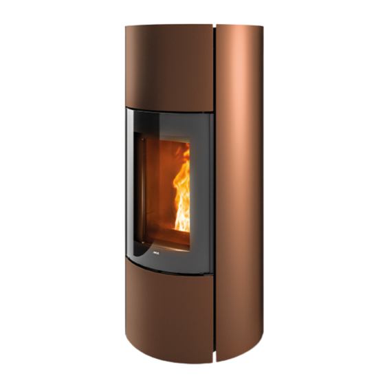
6-HOW THE STOVE ARRIVES Live electrical parts: only power the product once it has been fully assembled. On delivery, the stove has no metal cladding, as shown in the image below. Take the boxes with the two claddings (side and front/rear) and prepare them for assembly. The claddings are already fully assembled and must be fitted on the stove according to the instructions on the following pages. -
Page 30: 7-Removing The Top
7-REMOVING THE TOP DISASSEMBLING THE TOP To remove the upper top ‘G’ , follow the steps below: • remove the two screws “x” at the front of the top (firebox side) • lift the top “G” and put it in a safe place... -
Page 31: 8-Cladding Assembly
8-CLADDING ASSEMBLY UPPER PANEL ASSEMBLY Take the upper front panel ‘D’ , three screws“x” and two washers “y” from the packaging. Place panel “D” on the stove so that the top of the front panel rests on the top of the stove. Fasten panel “D” at the bottom (with the firebox door open) with screw “x”. - Page 32 8-CLADDING ASSEMBLY Fasten the panel “D” at the top with the two washers “y” and the two screws “x”.
- Page 33 8-CLADDING ASSEMBLY LOWER PANEL ASSEMBLY Take the lower front panel “C” and the two screws “k” from the package (the screws are to be used if the two screws “g” are missing in the structure). Remove the two screws “j” from the structure of the stove and remove the bracket “O”. Technical Dept.
- Page 34 8-CLADDING ASSEMBLY Remove the screw “g” from the lower part of the bracket “O”. Insert the bracket “O” into the frame of the panel “C” and secure it at the bottom with the screw “g” just removed (if screws “g” are not present, use those supplied “k”).
- Page 35 8-CLADDING ASSEMBLY Now fasten panel “C” to the stove structure using the two screws “j” (removed earlier). Technical Dept. - All rights reserved - Reproduction prohibited...
- Page 36 8-CLADDING ASSEMBLY ADJUSTING THE LOWER PANEL It is possible to adjust the magnet “r” by means of the nut “v”. Then try to make the lower front panel “C” flush with the decorative door “F”. The magnet “r” blocks the front panel “C” by means of the coupling to point “s”.
- Page 37 8-CLADDING ASSEMBLY RIGHT SIDE PANEL ASSEMBLY Take panel “A” from the package (these are two identical panels to be placed on the right or left). At the bottom insert hook “v” from panel “A” into hole “s” in the base of the stove structure. Technical Dept.
- Page 38 8-CLADDING ASSEMBLY Take two screws “x” and two washers “y” and secure the panel at the top.
- Page 39 8-CLADDING ASSEMBLY ASSEMBLY OF LEFT SIDE PANEL Repeat the same operations for the left side panel “A”. Technical Dept. - All rights reserved - Reproduction prohibited...
- Page 40 8-CLADDING ASSEMBLY REAR PANEL ASSEMBLY Take the panel “B” from the package with 4 screws “x” and 2 washers “y”. Insert the panel “B” into the structure so that the two slots “z” match the holes in the rear panel “F” already installed on the stove (also see image below). The panel “B”...
- Page 41 8-CLADDING ASSEMBLY At the top, secure the panel “B” by means of the two screws “x” and two washers “y” Technical Dept. - All rights reserved - Reproduction prohibited...
- Page 42 8-CLADDING ASSEMBLY UPPER TOP ASSEMBLY Take the top “G” removed earlier and set it at the top of the stove with a feather keys for opening the pellet loading door towards the back of the stove. Take the two screws “x” and secure the top “G” to the stove from above.
- Page 43 8-CLADDING ASSEMBLY REMOVING THE REAR PANEL If it is necessary to intervene on any stove component, proceed as follows to remove the rear panel “F” or the two lids “G” and “E”: • remove the screws “J”, so that element “E” can be removed •...
-
Page 44: 9-Door Opening
9-DOOR OPENING The Mood stove is fitted with two doors. To open the decorative door “F”, insert the cold handle “Z” into the designated joint on the door itself. To open firebox door “G”, insert the cold handle “Z” into the hole of handle and pull towards you. Caution! Only open the door when the stove is off and cold. -
Page 45: 10-Connections To Additional Devices
10-CONNECTIONS TO ADDITIONAL DEVICES Comfort Air ducting Comfort Air stoves can channel the air into other rooms through the connection with the accessory pipes to the rear extension “S” provided as standard. The outlet air pipe can reach very high temperatures, even around 150°C: therefore, it must be adequately insulated with suitable material, especially points that could come in contact with flammable surfaces or parts that are affected by heat (e.g. - Page 46 10-CONNECTIONS TO ADDITIONAL DEVICES Attention! It is mandatory to install the vents with “V” netting (1 or 2 depending on the type of appliance) on the rear “S” output for safety purposes and to prevent the rear wall from being hit directly by the hot air flow, generating halos, blackening or even dangerous heating in the case of flammable walls.
-
Page 47: 11-Electrical Connection
11-ELECTRICAL CONNECTION ELECTRICAL CONNECTION First connect the power cable to the back of the stove and then to a wall socket. It is recommended to disconnect the power cable when the stove is not used. ELECTRICAL STOVE CONNECTION The cable must never come into contact with the smoke exhaust pipe or any other part of the stove. STOVE POWER SUPPLY Connect the power cable to the back of the stove and then to a wall socket. - Page 48 11-ELECTRICAL CONNECTION USB SOCKET There is a USB socket on the back of the stove, if a software update is required; the ceramic/metal parts do not have to be removed to reach the socket directly in the circuit board (pos. 13 in the PCB). Attention! The USB socket must be used by skilled technicians.
-
Page 49: 12-Loading The Pellets
12-LOADING THE PELLETS LOADING THE PELLETS The fuel is loaded from the top of the stove by lifting rear top hatch “W” and pellet loading door “Q”. To open both doors, insert the cold handle “Z” in the designated hole “s”. Pour the pellets in slowly so that they are deposited at the bottom of the hopper. - Page 52 MCZ GROUP S.p.A. Via La Croce n°8 33074 Vigonovo di Fontanafredda (PN) – ITALY Telephone: 0434/599599 a.s. Fax: 0434/599598 Website: www.mcz.it e-mail: mcz@mcz.it 8902330800 REV.0 15/07/2024...
Need help?
Do you have a question about the MOOD COMFORT AIRMATIC 8 M2 CORE and is the answer not in the manual?
Questions and answers