
Related Manuals for MCZ MOOD COMFORT AIR 8 M1


Summary of Contents for MCZ MOOD COMFORT AIR 8 M1
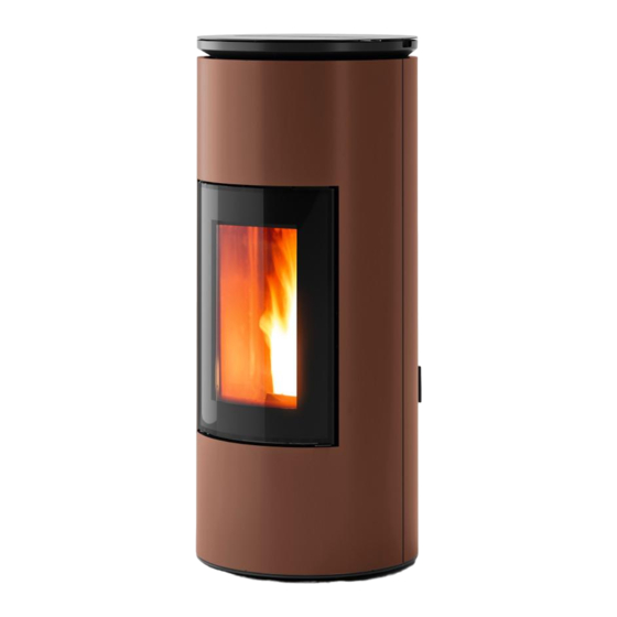
- Page 1 INSTALLATION GUIDE SEALED PELLET STOVE MOOD COMFORT AIR 8 M1 PART 1 - REGULATIONS AND ASSEMBLY Instructions in English...
-
Page 2: Table Of Contents
TABLE OF CONTENTS TABLE OF CONTENTS ....................II INTRODUCTION ......................1 1-WARNINGS AND WARRANTY CONDITIONS ..............2 2-INSTALLATION ......................9 3-DRAWINGS AND TECHNICAL FEATURES ..............18 4-UNPACKING ......................20 5-CLADDING REMOVAL ....................23 6-OPENING THE DOORS .....................32 7-CONNECTIONS TO ADDITIONAL DEVICES ..............33 8-LOADING THE PELLETS ...................37... -
Page 3: Introduction
REVISIONS TO THE PUBLICATION The content of this manual is strictly technical and the property of MCZ Group Spa. No part of this manual may be translated into other languages, adapted or reproduced, even in part, in other mechanical or electronic forms, photocopies, recordings or other, without the prior written authorisation from MCZ Group Spa. -
Page 4: 1-Warnings And Warranty Conditions
1-WARNINGS AND WARRANTY CONDITIONS SAFETY PRECAUTIONS • Installation, electrical connection, operating test and maintenance must only be carried out by authorised and qualified personnel. • Install the product in accordance with all local and national legislation and regulations in force in the region or state. • Only use the fuel recommended by the manufacturer. - Page 5 1-WARNINGS AND WARRANTY CONDITIONS • Do not put linen on the product to dry. Any drying racks or the like must be kept at a safe distance from the product. Fire hazard. • All liability for improper use of the product is entirely borne by the user and relieves the Manufacturer from any civil and criminal liability.
- Page 6 1-WARNINGS AND WARRANTY CONDITIONS exposed to weathering. • It is recommended not to remove the feet that support the product in order to guarantee adequate insulation, especially if the flooring is made of flammable materials. • In the event of a malfunction of the ignition system, do not force it to light by using flammable materials.
- Page 7 1-WARNINGS AND WARRANTY CONDITIONS INFORMATION: Please contact the retailer or qualified personnel authorised by the company to resolve a problem. • You must only use the fuel specified by the manufacturer. • When the product is switched on for the first time it is normal for it to emit smoke due to the paint heating for the first time. Therefore make sure the room in which it is installed is well ventilated.
- Page 8 1-WARNINGS AND WARRANTY CONDITIONS The replacement of the entire system or the repair of one of its components does not extend the warranty period, and the original expiry date remains unchanged. The warranty covers the replacement or free repair of parts recognised as being faulty at source due to manufacturing defects. In the event of a fault, to benefit from the warranty, the customer must keep the warranty certificate and provide it with the document given at the time of purchase to the Service Centre.
- Page 9 1-WARNINGS AND WARRANTY CONDITIONS SPARE PARTS In the event of a malfunction, consult the retailer who will forward the call to the Technical Assistance Department. Only use original spare parts. The retailer or service centre can provide all necessary information regarding spare parts. We do not recommend waiting for the parts to get worn out before having them replaced.
- Page 10 1-WARNINGS AND WARRANTY CONDITIONS Our solid bio-combustible products, (hereinafter called “Products”) are designed and manufactured in compliance with one of the following European standard harmonised to Regulation (UE) no. 305/2011 for construction products: EN 14785: “Residential space heating appliances fired by wood pellets” EN 13240: “Room heaters fired by solid fuel.”...
-
Page 11: 2-Installation
2-INSTALLATION The instructions in this chapter refer explicitly to the Italian installation regulation UNI 10683. In any case, always observe the regulations in force in the country of installation. PELLETS Wood pellets are manufactured by hot-extruding compressed sawdust which is produced during the working of natural dried wood. The compactness of the material is guaranteed by the lignin contained in the wood itself and allows pellets to be produced without glue or binders. - Page 12 2-INSTALLATION FOREWORD The installation position must be chosen according to the room, smoke extraction system and flue. Check with local authorities whether there are any restrictive regulations in force regarding the combustion air inlet, the smoke outlet system, the flue or the chimneypot. The manufacturer declines all responsibility in the event of installations that do not comply with the laws in force, incorrect room air exchange, electrical connection non-compliant with the standards and inappropriate use of the appliance.
- Page 13 2-INSTALLATION FOREWORD The Chimney Flue chapter has been drawn up with reference to the provisions of European Standards (EN13384 - EN1443 - EN1856 - EN1457). The chapter provides indications for installing an efficient and correct flue but is under no circumstances to substitute the regulations in force, which the qualified technician must be in possession of.
- Page 14 2-INSTALLATION TECHNICAL CHARACTERISTICS Have the efficiency of the flue checked by an authorised technician. The flue must be sealed against flue gasses, in a vertical direction without narrowing, be made with materials impermeable to smoke, condensation, thermally insulated and suitable to resist normal mechanical stress over time (we recommend fireplaces made of A/316 or refractory material with insulated round section double chamber).
- Page 15 2-INSTALLATION ROOF AT 60° ROOF AT 45° 45° 60° A = MIN. 2.60 metres A = MIN. 2.00 metres FIGURE 5 FIGURE 6 B = DISTANCE > 1.20 metres B = DISTANCE > 1.30 metres C = DISTANCE < 1.20 metres C = DISTANCE <...
- Page 16 2-INSTALLATION MAINTENANCE The flue must be kept clean, since the deposit of soot or unburned oils reduces the cross-section reducing the draft and thus compromising the efficient operation of the stove and, if large build-ups accumulate, can catch fire. The flue and chimneypot must be cleaned and checked by a qualified chimney sweep at least once a year.
- Page 17 2-INSTALLATION EXTERNAL AIR INLET It is mandatory to provide an adequate external air inlet that supplies the combustion air required for the product to work properly. The flow of air between the outside and the installation room may be direct, through an inlet in an external wall of the room (preferable solution see Figure 9 a);...
- Page 18 2-INSTALLATION DISTANCE (metres) The air inlet must be at a distance of: 1.5 m BELOW Windows, doors, smoke outlets, cavities, ..1.5 m HORIZONTALLY Windows, doors, smoke outlets, cavities, ..0.3 m ABOVE Windows, doors, smoke outlets, cavities, ..1.5 m AT A DISTANCE from smoke outlet CONNECTION TO THE FLUE...
- Page 19 2-INSTALLATION EXAMPLES OF CORRECT INSTALLATION 1. Installation of Ø120mm flue with hole for the passage of the pipe increased by: minimum 100mm around the pipe if next to non flammable parts such as cement, brick, etc.; or minimum 300mm around the pipe (or as required by rating plate) if next to flammable parts such as wood etc.
-
Page 20: 3-Drawings And Technical Features
3-DRAWINGS AND TECHNICAL FEATURES DRAWINGS AND CHARACTERISTICS MOOD COMFORT AIR 8 M1STOVE DIMENSIONS Ø80 Ø60 Ø80... - Page 21 3-DRAWINGS AND TECHNICAL FEATURES TECHNICAL CHARACTERISTICS MOOD COMFORT AIR 8 M1 Energy Efficiency Class Nominal output power 8.1 kW (6966 kcal/h) Minimum power output 2.3 kW (1978 kcal/h) Efficiency at Max 90.9% Efficiency at Min 92.6% Temperature of exhaust smoke at Max 188 °C...
-
Page 22: 4-Unpacking
4-UNPACKING PREPARATION AND UNPACKING The packaging consists of a recyclable cardboard box in line with RESY standards and a wooden pallet. All packaging materials can be reused for similar use or eventually disposed of as urban solid waste, in compliance with the regulations in force. After having removed the packaging make sure the product is intact. - Page 23 4-UNPACKING REMOVING THE FASTENING BRACKETS To remove the stove from the pallet, you must remove the two screws “u” and plate “s” from the stove’s foot. There are four brackets “s”. Technical Dept. - All rights reserved - Reproduction is prohibited...
- Page 24 4-UNPACKING Position the stove and connect it to the flue pipe. Use the 4 adjustable feet (J), to level the stove correctly so that the smoke outlet is lined up with the connecting pipe. If the stove needs to be connected to an outlet pipe which goes through the rear wall (to connect to the flue), take utmost care to make sure that the joint is not forced.
-
Page 25: 5-Cladding Removal
5-CLADDING REMOVAL On delivery, the Mood stove has steel cladding, as shown in the image below. The following pages have indications for removing the cladding (see pieces in figure below). Live electrical parts: only power the product once it has been fully assembled. - Page 26 5-CLADDING REMOVAL DISASSEMBLING THE TOP The top consists of two parts: • A- rear part • B - front part To remove the top proceed as follows: • lift the cover “A” • remove the two screws “x” • release the hook “y” on the top “B” from the plate “k” on the part of top “A” •...
- Page 27 5-CLADDING REMOVAL REMOVING THE FRONT PANEL After having removed the top (“A” and “B”) you may remove the decorative cladding panels. To remove the front panel “C” proceed as follows: • remove the three screws “s” at the top of the stove •...
- Page 28 5-CLADDING REMOVAL • at this point lift the front panel “C” and extract the holes “u” on the panel from the pin “t” at the base of the stove...
- Page 29 5-CLADDING REMOVAL AESTHETIC DOOR REMOVAL Attention! It is advisable to remove the aesthetic door before the front panel in order to avoid damaging the latter and to facilitate the process of removal. Remove the door as follows: • open the door •...
- Page 30 5-CLADDING REMOVAL REMOVING THE REAR PANEL Before removing the rear cladding “F” the panel “D” and “E” must be removed as follows: • remove the two screws “j”, so that element “E” can be removed • remove the 8 screws “h” •...
- Page 31 5-CLADDING REMOVAL REMOVING REAR CLADDING PANEL After having removed the panel “D”, remove the two screws “i” at the bottom in the rear. Looking at the stove on the front right-hand side, remove the three screws “o”. Technical Dept. - All rights reserved - Reproduction is prohibited...
- Page 32 5-CLADDING REMOVAL On the front left-hand side, remove the three screws “o” like on the right. Remove the two screws “v” at the top in the rear.
- Page 33 5-CLADDING REMOVAL Now you may remove the panel “F”and put it in a safe place. Technical Dept. - All rights reserved - Reproduction is prohibited...
-
Page 34: 6-Opening The Doors
6-OPENING THE DOORS The Mood stove is fitted with two doors. To open the decorative door “G” insert cold handle “Z” into the designated joint on the door itself. To open firebox door “H”, insert the cold handle“Z” into the hole of handle and pull. Attention! Only open the doors when the stove is switched off and cold. -
Page 35: 7-Connections To Additional Devices
7-CONNECTIONS TO ADDITIONAL DEVICES USB SOCKET There is a USB socket on the back of the stove, if a software update is required; the ceramic/metal parts do not have to be removed to reach the socket directly in the circuit board (pos. 5 in the PCB). Attention! The USB socket must be used by skilled technicians. - Page 36 7-CONNECTIONS TO ADDITIONAL DEVICES Comfort Air ducting Comfort Air stoves can channel the air into other rooms through the connection with the accessory pipes to the rear “S” shaped flange provided as standard. The recommended maximum duct length is 8 metres per fan. It is advisable to set up ducts of similar length to distribute the hot air evenly in the various rooms.
- Page 37 7-CONNECTIONS TO ADDITIONAL DEVICES Attention! It is mandatory to install the vents with “V” netting (1 or 2 depending on the type of appliance) on the rear “S” output for safety purposes and to prevent the rear wall from being hit directly by the hot air flow, generating halos, blackening or even dangerous heating in the case of flammable walls.
- Page 38 7-CONNECTIONS TO ADDITIONAL DEVICES ELECTRICAL CONNECTION First connect the power cable to the back of the stove and then to a wall socket. It is recommended to disconnect the power cable when the stove is not used. The cable must never come into contact with the smoke exhaust pipe or any other part of the stove. ELECTRICAL STOVE CONNECTION STOVE POWER SUPPLY Connect the power cable to the back of the stove and then to a wall socket.
-
Page 39: 8-Loading The Pellets
8-LOADING THE PELLETS LOADING PALLETS The fuel is loaded from the top of the stove by lifting rear top hatch “A” and pellet loading door “T”. To open both doors, insert the cold handle “Z” in the designated hole. Pour the pellets in slowly so that they are deposited at the bottom of the hopper. If loading pellets when the stove is running, open the door of the tank using the stove mitten that comes with the stove itself. - Page 40 MCZ GROUP S.p.A. Via La Croce n°8 33074 Vigonovo di Fontanafredda (PN) – ITALY Telefono: 0434/599599 a.s. Fax: 0434/599598 Internet: www.mcz.it e-mail: mcz@mcz.it 8901853200 REV.0 07/03/2022...
Need help?
Do you have a question about the MOOD COMFORT AIR 8 M1 and is the answer not in the manual?
Questions and answers