Advertisement
Quick Links
Engineering Data
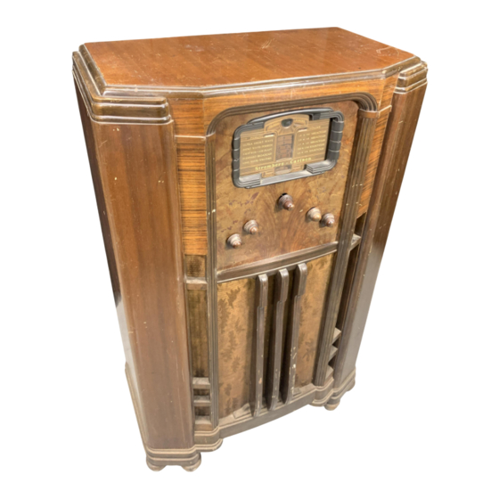
Stromberg-Carlson No. 150 Radio Receiver
STROMBERG-CARLSON TELEPHONE MANUFACTURING COMPANY
Rochester, New York
ELECTRICAL SPECIFICATIONS
Type of Circuit_Superheterodyne
Tuning Ranges—
X—145 to 370 Kc.; A—530 to 1700 Kc.; B—1700 to 5600 Kc.; C—5600 to 18,000 Kc.; D—18,000 to 60,000 Kc.
Number and Types of Tubes_4 No. 6K7, 1 No. 6A8, 1 No. 6J7, 2 No. 6H6, 2 No. 6L6,1 No. 6E5, 1 No. 5Z3
Power Supply Voltage_105 to 125 Volts
Power Supply Frequency_25 to 60 Cycles and 50 to 60 Cycles
Input Power Rating_167 Watts
Frequency of Intermediate Amplifier_465 Kilocycles
APPARATUS SPECIFICATIONS
No. 150-L_50 to 60 Cycles; P-26454 Chassis Assembly; P-26170 Loud Speaker
No. 150-LB_25 to 60 Cycles; P-26455 Chassis Assembly; P-26170 Loud Speaker
CIRCUIT DESCRIPTION
The No. 150 Receiver is a twelve tube, "Adjustable High Fidelity" receiver employing metal tubes, includ¬
ing the new "Beam" power tubes. There are five tuning ranges in this receiver, one of which is the Ultra-Short
Wave range. This range is also referred to as the Ultra-High Frequency (U. H. F.) range and also as the "D"
band.
This receiver uses a Carpinchoe high fidelity dynamic speaker, and has incorporated in it the exclusive
"Patent Applied For", Stromberg-Carlson "Tri-Focal" tuning system and the exclusive Stromberg-Carlson Acous¬
tical Laboratories' revolutionary new development, the "Acoustical Labyrinth".
This new device extends the
bass response, provides reproduction only from the front of the cabinet, and eliminates all cabinet resonance.
Audio reproduction is further improved in this receiver by employing sound diffusing vanes in front of the loud
speaker opening which distribute the higher pitched tones, thereby providing excellent reproduction in all parts
of the room by spreading out these directional frequencies.
Maximum selectivity between adjacent stations located in the standard broadcast band is obtained by the
use of an additional tuned radio' frequency ("Bi-resonator") circuit. When either the "X", "B", "C", or "D"
ranges are in operation, this additional tuned radio frequency circuit is automatically cut out of the receiver
circuit. Adjustable high fidelity is obtained from this receiver by means of the variable band width, interme¬
diate frequency transformers which are used in the two intermediate amplifier stages.
The various tubes are used in this receiver as follows: One No. 6K7 tube is used in the R. F. Amplifier,
one No. 6K7 is used in the First I. F. Amplifier, another No. 6K7 is used in the Second I. F. Amplifier, and the re¬
maining No. 6K7 tube is used in the Audio Amplifier. The No. 6A8 tube is used as a Modulator tube, and the
No. 6J7 tube is used as the Oscillator tube.
One No. 6H6 tube is used as the Demodulator tube, and the other
No. 6H6 tube is used as the Automatic Volume Control tube.
The two No. 6L6 tubes are used in the Audio
Power Output Stage.
The No. 6E5 tube is used as the indicator of the Tri-Focal Tuning System, and the No.
5Z3 tnbe is the Rectifier tube of the power supply unit.
3RD.I.F.
2ND.I.F.
IST.I.F.
TRANSFORMER TRANSFORMER TRANSFORMER
LEFT HAND FRONT VIEW OF CHASSIS
Fig. 1.
Terminal Layout for Voltage Measurement Chart and Location of the
Various Aligning Capacitors.
P-26993
Form 2151
Issue 1
Printed In U. S. A.
Advertisement


Need help?
Do you have a question about the 150 and is the answer not in the manual?
Questions and answers