Advertisement
Quick Links
Engineering Data
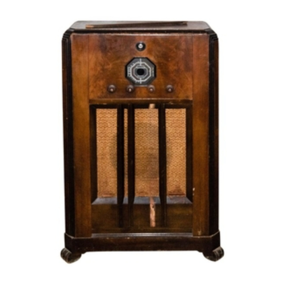
Stromberg-Carlson No. 228 Radio Receivers
STROMBERG-CARLSON TELEPHONE MANUFACTURING COMPANY
Rochester, New York
ELECTRICAL SPECIFICATIONS
Type of Circuit_
Tuning Ranges_
Number and Types of Tubes_
Voltage Rating_
Input Power Frequency_
Input Power Rating_
Frequency of Intermediate Amplifier
_Superheterodyne
_A—540 to 1500 Kc.; B—1450 to 3500 Kc.; C—5900 to 18,000 Kc.
1 No. 6A8,1 No. 6K7,1 No. 6Q7,1 No. 6F6G, 1 No. 6G5,1 No. 5Y4G
_105 to 125 Volts, A. C.
_25 to 60 Cycles and 50 to 60 Cycles
_56 Watts
_ 465 Kilocycles
APPARATUS SPECIFICATIONS
No. 228-H Receiver_50 to 60 Cycles; P-27543 Chassis; P-27557 Loud Speaker
No. 228-HB Receiver_25 to 60 Cycles; P-27544 Chassis; P-27557 Loud Speaker
No. 228-L Receiver_50 to 60 Cycles; P-27543 Chassis; P-27605 Loud Speaker
No. 228-LB Receiver_25 to 60 Cycles; P-27544 Chassis; P-27605 Loud Speaker
CIRCUIT DESCRIPTION
These receivers are six tube superheterodyne receivers employing metal tubes and a highly efficient dynamic
speaker. There are three tuning ranges; the limits of each tuning range are listed under the "Electrical Speci¬
fications" given above. These receivers are also equipped with a low level bass frequency compensating net¬
work, which in conjunction with the volume control circuit gives balanced reproduction at any setting of the
volume control.
The various tubes are used in these receivers as follows: The No. 6A8 tube functions as both Modulator
and Oscillator. The No. 6K7 tube is used in the I. F. Amplifier and the No. 6Q7 tube is used as the Demodulator,
A. V. C., and Audio Amplifier tube. The No. 6F6G tube is used in the Audio Power Output Stage and the No.
6G5 tube is used for indicating resonance in the Tuning Indicator System. The No. 5Y4G is the Rectifier tube of
the power supply unit.
NORMAL VOLTAGE READINGS
The various values of voltages listed in the following table are obtained by measuring between the various
tube socket contacts and the chassis base, with the tubes in their respective sockets. The receiver is, therefore,
in operation when the measurements are made. Figure 1, shows the terminal layout of the sockets with the
proper terminal numbers.
Voltages are given for a line voltage of 120 volts, and allowance should be made for differences when the
line voltage is higher or lower. A meter having a resistance of 1000 ohms per volt should be used for measuring
the D. C. voltages. Voltage values shown are those obtained on the lowest possible scale of a meter having the
following ranges: 0-2.5, 0-10, 0-100, 0-250, 0-500, 0-1000 volts except when an asterisk appears after any given
voltage value in which case the 250 volt scale was used.
Tube
Circuit
Cap
Terminals of Sockets
Heater Voltages
Between Heater
Terminals
1
2
3
4
5
6
7
8
Socket
Terminal
Numbers
Volts
6A8
Mod.—Osc.
0
0
0
+210 +65
—20
+180
6.1
+1.6
2-7
6.1
6K7
I. F. Amp.
0
0
0
+220 +90
+2.5
—
6.1
+2.5
2-7
6.1
6Q7
Dem.—A. V. C.
—Audio
0
0
0
+100
0
0
+100
6.1
+1.6
2-7
6.1
6F6G Audio Output
—
0
0
+210 +220
0
0
6.1
+13
2-7
6.1
6G5
Tuning Ind.
—
0
+2.4*
0
+220
—
6.1
1-6
6.1
5Y4G
Rectifier
—
0
0
335
335
—
+340 +344
7-8
h.9
Speak er Socket
—
+340
0
0
+340 +340
—
+220
Receiver tuned to 1000 Kc., no signal. A. C. voltages are indicated by italics.
P-27H83
Form 2102
Issue 1
Printed ill U. S. A.
Advertisement


Need help?
Do you have a question about the 228 and is the answer not in the manual?
Questions and answers