Advertisement
Quick Links
Engineering Data
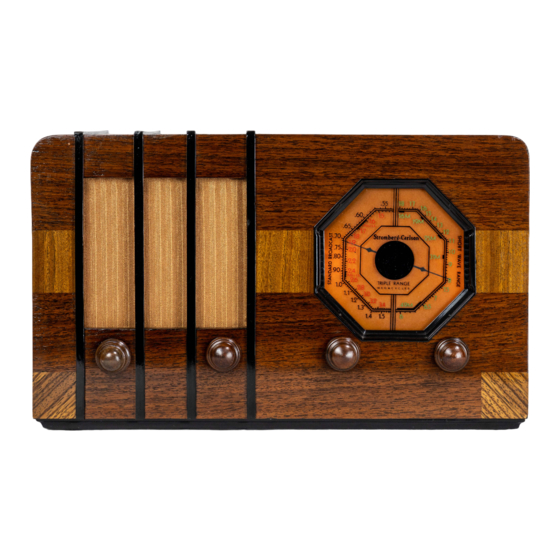
Stromberg-Carlson No. 125 AC-DC Radio Receivers
STROMBERG-CARLSON TELEPHONE MANUFACTURING COMPANY
Rochester, New York
ELECTRICAL SPECIFICATIONS
Type of Circuit_
Tuning Ranges_
Number and Types of Tubes_
Voltage Rating_
Power Frequency (For AC Operation)
Input Power Rating_
Intermediate Frequency_
-Superheterodyne
A—540 to 1500 Kc.; B—1450 to 3500 Kc.; C—5600 to 18,000 Kc.
_1 No. 6A8,1 No. 6K7, 1 No. 6Q7, 1 No. 43, 1 No. 25Z5
-105 to 125 Volts
-50-60 Cycles
-45 Watts
_465 Kilocycles
APPARATUS SPECIFICATIONS
No. 125,--50 to 60 Cycles (For AC Operation)-P-26052 Chassis Assembly
CIRCUIT DESCRIPTION
This triple range, superheterodyne receiver has five tubes and may be operated on a power supply circuit
of either alternating or direct current at the voltages and frequency (for A. C. operation) specified above.
The various tubes are used in this receiver as follows: One No. 6A8 tube functions as both Oscillator and
Modulator; one No. 6K7 tube is used in the I. F. Amplifier; the No. 6Q7 tube is used as the Demodulator, A. V. C.,
and Audio Amplifier tube. The No. 43 tube is used in the Audio Power Output stage, and the No. 25Z5 tube is
used as the Rectifier tube for the receiver "B" voltage supply.
NORMAL VOLTAGE READINGS
These voltage readings are obtained by measuring between the various tube socket contacts and the heavy
bus wire with the tubes in their respective sockets. The receiver is, therefore, in operation when the measure¬
ments are made. The heavy bus wire, which is the negative side of the grid and plate voltages, is plainly marked
on the schematic and wiring diagram shown on pages three and five.
Figure 1, shows the terminal layout of
the sockets with the proper terminal numbers.
Voltages are given for a line voltage of 120 volts, A. C. Allowance should be made for the difference when
the line voltage is higher or lower.
IMPORTANT—If the receiver is operated from a direct current power supply circuit, the various volt¬
ages measured will be slightly lower than those listed in the table for A. C. operation. A meter having a resist¬
ance of 1000 ohms per volt should be used for measuring the D. C. voltages. Voltage values shown are those ob¬
tained on the lowest possible scale of a meter having the following ranges: 0-2.5, 0-10, 0-100, 0-250, 0-500,
0-1000 volts except when an asterisk appears after any given voltage value in which case the 1000 volt scale was
used.
When the receiver is being operated from an alternating current power supply circuit, it will be necessary
to have a high resistance A. C. voltmeter for checking the A. C. voltages.
Tube
Circuit
Cap.
Terminals of Sockets
Heater Voltages
Between Heater
Terminals
Terminal
Numbers
Volts
1
2
3
4
5
6
7
8
6A8
Mod.—Osc.
—.02 125
0
+ 97 + 60 —
7
+73 6.3
+1.3
2-7
6.3
6K7
I. F. Amp.
0
125
0
+ 97 + 91 +
3 —
18
+3
2-7
6.3
6Q7
Dem.—A.V.C.
—Audio
0
0
0
+55*
0
0
—
6.2
+1
2-7
6.3
43
Audio Output
—
43
+ 90 + 96
0
+ 12
18
—
—
1-6
24
25Z5
Rectifier
—
65
112
+102 +102 112
43
-—
—■
1-6
22
Voltage across pilot lamps—8.2 volts
A.C. voltages are indicated by italics; when the receiver is operated from a D.G, power
supply, D.C voltages will be obtained in place of the A.C. voltages.
Receiver tuned to 1000 kc., no signal.
P-28429 Form No. 1898 Issue 1 Printed in V. 6. 4.
Advertisement


Need help?
Do you have a question about the 125 and is the answer not in the manual?
Questions and answers