Advertisement
Quick Links
ENGINEERING DATA
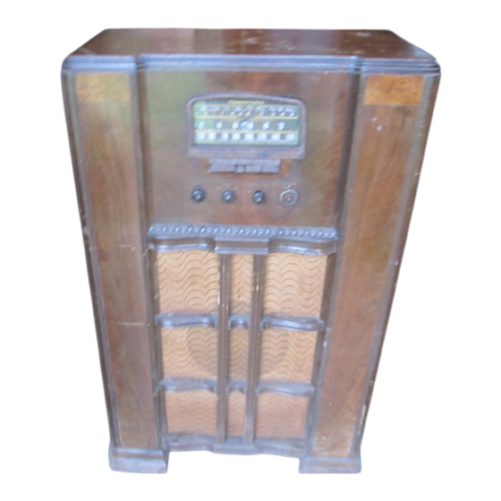
STROMBERG-CARLSON NO. 435 RADIO RECEIVERS
STROMBERG-CAELSON TELEPHONE MANUFACTURING COMPANY
ROCHESTER, NEW YORK
IDENTIFICATION TABLE
Model
Input Power Frequency
Chassis
Cabinet
Speaker
435-M
50-60 Cycles
31481 Amp. Mod.
31482 Freq. Mod.
31840
30359
SPECIFICATIONS
Tuning Ranges_
Voltage Rating_
Type of Circuit_
Number and Type of Tubes—16
1—6A8 Oscillator and Modulator (A. M.)
1— 6K7 I. F. Amplifier (A. M.)
2— 6H6 Demodulators (A. M. and F. M.)
1— 6SA7 Oscillator and Modulator (F. M.)
2— 6AC7 I. F. Amplifiers (F. M.)
1—6SJ7 Limiter (F. M.)
Input Power Rating_
Intermediate Frequency_
Speaker Voice Coil Impedance at 400 Cycles_
Speaker Field Coil Resistance_
Frequency Modulation 40 to 44 Me. (40,000 to 44,000 Kc.)
Short Wave 5.8 to 18 Me. (5,800 to 18,000 Kc.)
Standard Broadcast .54 to 1.7 Me. (540 to 1,700 Kc.)
-105 to 125 Volts
-Superheterodyne with Electric Tuning
1— 6SK7 Tuning Indicator Amplifier (F. M.)
2— 6SQ7 Audio Amplifier and Audio Inverter
2—6V6G Output
1— 6AF6G Tuning Indicator
2— 80 Rectifiers
-140 Watts
455 Kilocycles (Amplitude Modulation)
2.1 Megacycles (Frequency Modulation)
-Approximately 1.5 Ohms
-Approximately 1050 Ohms
FEATURES
This is a sixteen tube, three gang, three range receiver,
designed for the reception of both amplitude and fre¬
quency modulated stations.
Eight button automatic tuning is provided. The tuning
unit is composed of a group of coils which are adjust¬
ed by means of iron cores, so that seven favorite sta¬
tions in the standard broadcast range may be set up.
The eighth button is for switching from amplitude to
frequency modulation. Tone is adjusted by a variable
tone control and the dial is of the slide rule type edge,
lighted for clear visability without glare.
Provision is made for a record player to be used with
this receiver without additional wiring.
The chassis is designed to provide excellent sensitiv¬
ity and tone quality and the power output is very
good. The selectivity and freedom from interference
should be quite satisfactory under normal operating
conditions.
FREQUENCY MODULATION: The "Armstrong Wide-
Swing Frequency Modulation System" used in this
receiver is an outstanding development in radio. It
makes possible:
1. Static-Free Reception;
Both natural and man-made static is virtually
eliminated.
2. Noise free reception;
The tube and set noises present in ordinary am¬
plitude modulation receivers are virtually elim¬
inated.
3. Extreme high fidelity reception;
Noise free reproduction of an audio range lim¬
ited only by the capacity of the human ear or
the audio system of the receiver is possible with¬
out interference.
4. Interference free reception;
Two stations cannot be received at the same
time.
This system is patented and Stromberg-Carlson man¬
ufactures these receivers under an Armstrong license.
The Federal Communications Commission has estab¬
lished five channels between 40 and 44 megacycles for
frequency modulated transmitting stations. Since this
is a comparatively high frequency, the distance over
which reception is possible is limited. It should also
be noted that the fidelity may be limited by telephone
lines, or by program transcriptions, although this con¬
dition will, undoubtedly, be improved as time goes on.
SPECIAL CIRCUITS. A tuning indicator having two
apertures is used in this receiver. One aperture will
operate when-tuning stations in the standard broad¬
cast and short-wave ranges and the other aperture
will operate when tuning stations in the frequency
modulation range. Stations should be tuned for max¬
imum closing of the tuning indicator.
Iron core coils are used in the standard broadcast and
short-wave ranges to provide greater accuracy of
alignment. In addition a thernal drift compensator is
included in the circuit. The audio system employs a
special inverter push-pull circuit designed to provide
excellent fidelity. The power transformer has an
electro-static shield to reduce line noises to a mini¬
mum and the chassis is thoroughly shielded through¬
out.
AUTOMATIC TUNING. An adjustable iron core coil
type of automatic tuning is employed and the stations
may be easily located by properly utilizing the con¬
centric adjusting screws provided. A special tool
identified as SD-70 Screwdriver will help materially
in setting up the automatic tuning.
MANUAL TUNING.
Important.
When tuning sta¬
tions manually in the Standard Broadcast or Short
Wave ranges be sure that the push button designated
"Freq. Mod." is not pushed in.
PHONOGRAPH OPERATION. A jack is provided on
the back of the chassis into which a record player
may be plugged and a switch is provided next to it for
switching from "Radio" to "Phonograph".
TELEVISION. Switching to phonograph also makes
the audio amplifier and loud speaker available for use
with television receivers designed for this type of
sound reproduction.
P-31999
Issue 1
Printed in U. S. A.
Advertisement


Need help?
Do you have a question about the 435 and is the answer not in the manual?
Questions and answers