
Related Manuals for Huawei RMS-RELAY01A


Summary of Contents for Huawei RMS-RELAY01A
- Page 1 Part Number: 31505548 RMS-RELAY01A User Manual Issue Date 2023-01-09 HUAWEI TECHNOLOGIES CO., LTD.
- Page 2 Notice The purchased products, services and features are stipulated by the contract made between Huawei and the customer. All or part of the products, services and features described in this document may not be within the purchase scope or the usage scope. Unless otherwise specified in the contract, all statements, information, and recommendations in this document are provided "AS IS"...
-
Page 3: About This Document
About This Document About This Document Purpose This document describes the RMS-RELAY01A card in terms of its features, appearance, structure, installation, usage, and operations. The RMS-RELAY01A card is an optional communications component for the UPS2000-G-(6 kVA–20 kVA) series, UPS5000-A-(30 kVA–120 kVA) series, UPS2000-A-6KTTS-S, UPS2000- A-6KTTL-S, UPS2000-A-6KTTS-P, UPS2000-A-6KTTL-P, UPS2000-A-10KTTS-S, UPS2000-A-10KTTL-S, UPS2000-A-10KTTS-P , and UPS2000-A-10KTTL-P. - Page 4 Supported the UPS2000-A-(6 kVA–10 kVA) and UPS5000-A-(30 kVA–120 kVA) series. Issue 03 (2014-05-15) Updated the pictures in this document. Issue 02 (2013-08-24) Updated the pictures in this document. Issue 01 (2013-05-15) This issue is the first official release. Issue 06 (2023-01-09) Copyright © Huawei Technologies Co., Ltd.
-
Page 5: Table Of Contents
3.3 Dry Contact Output Relay Specifications........................8 4 Installation..........................9 4.1 Unpacking and Checking..............................9 4.2 Installation Preparations............................... 9 4.3 Installation Procedure................................. 10 4.4 RMS-RELAY01A Card Settings............................11 A Acronyms and Abbreviations..................... 14 Issue 06 (2023-01-09) Copyright © Huawei Technologies Co., Ltd. -
Page 6: Safety Information
To avoid damage, handle the RMS-RELAY01A card gently. Connect the DB25 port of the RMS-RELAY01A card only to a safety low- voltage circuit. Otherwise, the card may be damaged and even safety accidents may occur. -
Page 7: Overview
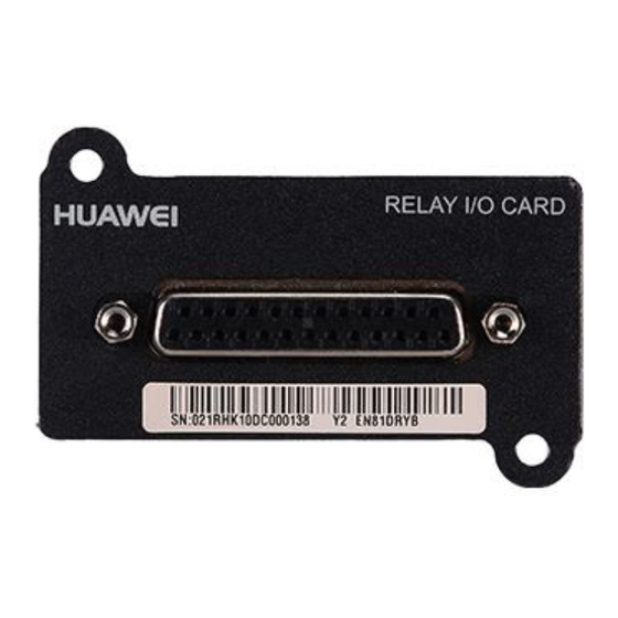
2 Overview Overview 2.1 Introduction The RMS-RELAY01A card is installed in an optional card slot on the UPS and is hot-swappable. The card provides six alarm dry contact outputs (normal mode, battery mode, bypass mode, battery undervoltage, bypass backfeed, and UPS fault) and two dry contact control inputs (one for the shutdown signal and the other reserved) for the UPS2000-G system. -
Page 8: Functions
2 Overview 2.2 Functions The card provides six alarm outputs, as described in Table 2-2. Specific alarms can be set for each dry contact through the monitoring board. Table 2-2 RMS-RELAY01A card functions Dry Contact Type Function Definition Output Normal mode... -
Page 9: Typical Application Scenario
4.4 RMS-RELAY01A Card Settings. 2.3 Typical Application Scenario The RMS-RELAY01A card applies to multiple application scenarios. This section describes only one typical application scenario. In this scenario, the RMS- RELAY01A card can report five working states of the host, as shown in Figure 2-1. -
Page 10: Functions And Features
Figure 3-1 Pins on the DB25 port Table 3-1 DB25 port definitions Pin No. Signal Input/Output Description AGND Output External analog ground INPUT2 Input Input terminal of external Boolean signal 2 None None Reserved Issue 06 (2023-01-09) Copyright © Huawei Technologies Co., Ltd. - Page 11 Output NO contact of dry contact 6 OUTPUT5– Output Common terminal of dry contact 5 OUTPUT4_B Output NC contact of dry contact 4 OUTPUT4_A Output NO contact of dry contact 4 Issue 06 (2023-01-09) Copyright © Huawei Technologies Co., Ltd.
-
Page 12: Db25 Communications Cable
1 3.2 DB25 Communications Cable Figure 3-2 DB25 communications cable The DB25 cable, which is delivered along with the RMS-RELAY01A card, is 1.5 meters long. To increase the length, add a magnetic ring to the connector of the DB25 cable. -
Page 13: Dry Contact Output Relay Specifications
Item Electrical Specifications Maximum contact power 30 W Rated contact voltage 30 V DC 60 V DC Rated contact current 0.5 A Input dry contact supply 12–24 V DC voltage range Issue 06 (2023-01-09) Copyright © Huawei Technologies Co., Ltd. -
Page 14: Installation
RMS-RELAY01A User Manual 4 Installation Installation 4.1 Unpacking and Checking After the RMS-RELAY01A card is delivered onsite, unpack it and check as follows: ● Visually inspect the appearance for shipping damage. If it is damaged, notify the carrier immediately. ●... -
Page 15: Installation Procedure
Figure 4-1 Removing the optional card slot cover Step 3 Insert the RMS-RELAY01A card into the optional card slot along the guide rails on both sides of the slot, as shown in Figure 4-2, and tighten the screws. -
Page 16: Rms-Relay01A Card Settings
4 Installation Figure 4-2 Inserting the RMS-RELAY01A into the optional card slot Step 4 Connect one end of the cable to the DB25 port on the RMS-RELAY01A card, and connect the other end to the customer's equipment, as shown in Figure 4-3. - Page 17 Step 2 Enter the password (the preset password is 000001). Step 3 Select Communication Card. Step 4 Press . On the Optional Card screen, set the RMS-RELAY01A card. NO TE Multiple states can be associated with one dry contact, but one state cannot be associated with multiple dry contacts.
- Page 18 Specifies the output dry contact associated with UPS faults. When a critical alarm is generated, this dry contact is enabled. The value ranges from Dry contact 1 to Dry contact 6. The default value is Dry contact 6. ----End Issue 06 (2023-01-09) Copyright © Huawei Technologies Co., Ltd.
-
Page 19: A Acronyms And Abbreviations
RMS-RELAY01A User Manual A Acronyms and Abbreviations Acronyms and Abbreviations economic control operation liquid crystal display uninterruptible power system Issue 06 (2023-01-09) Copyright © Huawei Technologies Co., Ltd.
Need help?
Do you have a question about the RMS-RELAY01A and is the answer not in the manual?
Questions and answers