
Related Manuals for VP instruments VPFlowMate probe


Summary of Contents for VP instruments VPFlowMate probe
- Page 1 VPFlowMate User Manual For VPFlowMate probe, and VPFlowMate in-line (with M12 8-pole connector) With VPStudio 1.0.19...
- Page 2 Revision: 25 May 2011 VPFlowMate is a registered trademark of Van Putten Instruments B.V. Our product, technology and software are protected by various patents, trademarks and copyrights. ©2001-2011 Van Putten Instruments B.V. All rights reserved. Van Putten Instruments Buitenwatersloot 335 2614GS Delft The Netherlands T: +31 (0)15 213 1580...
- Page 3 WARNING – READ THIS FIRST Congratulations! You have bought a state of the art insertion mass flow meter from VPInstruments! The VPFlowScope and VPFlowMate are versatile and easy to use and can be very powerful tools to monitor compressed air consumption. However, there are a few important issues you need to know before using these kind of instruments.
- Page 4 ® VPFlowMate user manual rev 25 May 2011...
-
Page 5: Table Of Contents
3. Mechanical installation ........................10 3.1 Gasses ............................10 3.2 Selecting the right installation point ................... 10 3.3 Installation of the VPFlowMate probe ..................13 3.4 Installation of the VPFlowMate in-line..................15 Electrical Connection ........................17 4.1 Plug and play (connection possibility to PC)................17 4.2 Stand alone .......................... - Page 6 ® VPFlowMate user manual rev 25 May 2011...
-
Page 7: Introduction
1. Introduction Thank you for choosing the VPFlowMate mass flow meter. The VPFlowMate probe and in-line are easy to use mass flow meters for compressed air. They help you to find cost savings in the shortest possible way. The VPFlowMate is the proven solution for mass flow measurements. The VPFlowMate measures mass flow and the total consumption of your compressed air. -
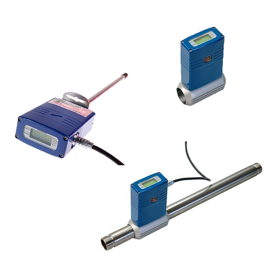
Page 8: Product Overview
VPFlowMate probe The VPFlowMate probe is an insertion mass flow meter. The insertion probe is recommended for use for measurement in pipe diameters above 2”. The VPFlowMate probe has the advantage that you can measure in different pipe diameters with the same device;... - Page 9 Display option The VPFlowMate in-line features a display. The display is The mass flow meters of optional for the VPFlowMate probe. The display shows: VPInstruments measure mass mass flow on the first line and total consumption on the flow independent from second line.
-
Page 10: Mechanical Installation
3. Mechanical installation In this chapter we show you the installation of the VPFlowMate in your factory in the pipe line. Learn how to select the right installation point and how to install your VPFlowMate in the pipe. 3.1 Gasses Your VPFlowMate can be used for compressed air and Nitrogen. - Page 11 Piping guidelines DONT’S DO’S Like any flow meter, the VPFlowMate requires minimum downstream piping. The immediate up- and downstream piping must be of sufficient length, straight and free of obstructions. Check de piping table on the next page for details! Weld beads on the internal wall of the pipe before or after the VPFlowMate, should be ground flush with the pipe wall...
- Page 12 Piping table General rule: The VPFlowMate should be installed with at least 20 times the pipe diameter upstream and at least 5 times the pipe diameter downstream, to avoid any distortion of the flow profile. For some exceptions the upstream length needs to be longer, or can be shorter. Check the piping table below for your application.
-
Page 13: Installation Of The Vpflowmate Probe
3.3 Installation of the VPFlowMate probe Prepare the installation The VPFlowMate probe can be inserted through a welding tap with internal 1/2 inch thread (see picture) or through a hot tap saddle (see below). We recommend using a 15..18 mm bore. The probe of the VPFlowMate has a diameter of 12.7mm. - Page 14 Do not over tighten to prevent damage to 10. Now your the probe. Pull the probe to VPFlowMate probe is 8. Retrieve the probe half the pipe diameter. check if the compression fitting installed. Adjust the safety line (and strap) to keep the is tight enough.
-
Page 15: Installation Of The Vpflowmate In-Line
They only need to know the pipe diameter to calculate the flow for you. How to configure your VPFlowMate probe is explained in the next chapters. - Page 16 Installation of VPFlowmate in-line with tubing kit When you ordered the tubing kit or a full start kit, the VPFlowMate in-line is delivered with an up and downstream piping kit, to ensure at least 20 times the pipe diameter (for 0,5 inch and 1 inch) upstream length.
-
Page 17: Electrical Connection
Familiarize yourself with the different connection possibilities of the VPFlowMate and their usage. (See appendix B for electrical information and CE and UL guidelines.) The VPFlowMate probe and in-line provide RS232, 4..20mA and pulse output. The cable wiring connections shown here: Always use a proper power supply. -
Page 18: Stand Alone
Usage: - For connection to PC for configuration of your VPFlowMate. The VPFlowMate probe needs to know the inner pipe diameter, to calculate the flow. The • pipe diameter needs to be entered with the VPStudio software. In the next chapter VPStudio is explained. -
Page 19: Using Pulse Output
The 4..20mA output default is from 0..100% of the flow range. The default settings for the different VPFlowMate models are: For the VPFlowMate probe you can change the 4..20mA output. You can change it to the unit m and you can set the maximum output. -
Page 20: Connection With Vpflowterminal
Pulse output (opto isolated relay/ NAMUR compatible) + 12..24 Volt Pulscounter 4.5 Connection with VPFlowTerminal When you cannot read out the display of your VPFlowMate, e.g. because your flow meter is too high, you can use the VPFlowTerminal; a remote display. For connection and further usage, we refer you to the sales team of VPInstruments and the user manual of the VPFlowTerminal. -
Page 21: Vpstudio Software
Or make your own RS232 connection, see appendix E. Basic configuration The VPFlowMate probe is a spot measurement device and needs to know the inner pipe diameter to give read out of flow in m /hr. Therefore you have to configure the VPFlowMate probe with this diameter. -
Page 22: Adding Your Vpflowmate
5.2 Adding your VPFlowMate To read out the VPFlowMate and to configure the device, you first have to create your VPFlowMate in the software. Click right mouse button in the explorer field and click ‘New device’. The ‘Device properties’ window appears. Write in the ‘Description’... -
Page 23: Status And Specifications
Click OK to confirm. The VPFlowMate is added in the explorer field. 5.3 Status and Specifications In the Status tab you see the specifications of your VPFlowMate. You can view for instance the serial number and the specifications like flow range. In current settings you can see the pipe diameter and the flow unit that are currently configured, including a view of the display with real-time data. -
Page 24: Configurating Your Vpflowmate
Choose the reference conditions of your application, to have immediately the right flow output to match your application. You can also reset the totalizer, by clicking ´Reset total´. For the VPFlowMate probe, you can lower the 20mA output to better fit the flow range of your application. -
Page 25: Real-Time Data
5.5 Real-time data Click the + in front of your VPFlowMate in the ‘Explorer field’ to open the tree. Click on ‘Real-time data’ to go to the graph. Go with your mouse in the graph, click right mouse button and ‘Acquire’ to read in the real-time data of your flow meter. - Page 26 Export to csv.file As long as you have the ´Real-time data´ selecting, the graph is reading in your flow data. Any time you can export the data so far by clicking right mouse button and go to ‘Export’. Choose a name and a place for your export file, click OK. The ‘Export Options’ dialog appears. Here you can choose which data to export and in what matter.
-
Page 27: Service
6. Service The VPFlowMate needs regular maintenance to ensure that the product is functioning properly. Especially when the product is used for mobile air audits, we recommend inspecting the instrument before and after every audit to ensure that the product has not been damaged. For precision measurement equipment such as the VPFlowMate, a proper maintenance program is key to reliable measurement results and a long product lifetime. -
Page 28: First Aid Help
6.5 First Aid Help Is your VPFlowMate not working correctly, please check the table below to perform the first diagnosis and to see if you can fix the problem. Contact us when you have any other problem or if you continue with having problems. -
Page 29: Specifications
7. Specifications Please always check the label of your product for the specifications VPFlowMate probe VPFlowMate in-line - Mass flow Measurement - Total consumption Flow sensor Measuring principle: Thermal mass flow Flow range: 0.5…150 mn/sec See range table below 0.5% of span. - Page 30 Electrical Outputs: RS232, 4..20mA (isolated), pulse (isolated) 12...24 VDC +/- 10 % Class 2 (UL) Power supply: Power consumption < 100mA. Peak power at start up 500mA Connection type: Multi pole connector M12 connector Approvals/conformity: EN 61326-1, EN 50082-1 UL/ CUL: 14 AZ, Industrial Control Equipment Range table VPFlowMate in-line and Lite Model...
-
Page 31: Appendix A: Mass Flow And Volume Flow
Appendix A: Mass flow and volume flow Definition of mass flow Mass flow rate is the mass of substance which passes through a given surface per unit time. Its unit is mass divided by time. This means: kilogram per second in SI units, and slug per second or pound per second in US customary units. -
Page 32: Appendix B: Electrical Installation
Appendix B: Electrical installation The VPFlowMate complies with the CE requirements as stated in the CE declaration. CE compliance can only be achieved when grounding and shielding directions are followed and proper cables and connector assemblies are used. Electrical connection guidelines- UL 508 Listing for USA & Canada The VPFlowMate is intended to be used with a Class 2 power source or Class 2 transformer in accordance with UL1310 or UL1585. -
Page 33: Appendix C. Extra Tips For Electrical Connection
Appendix C. Extra tips for electrical connection This appendix describes extra option for the output of the VPFlowMate. Creating from the passive current output an active current output. Power to 4 - 20 mA + + 12..24 Volt 4..20 mA Creating voltage output from 4-20 mA output using a register Power to 4-20 mA + + 12..24 Volt... -
Page 34: Appendix D: Pulse Output
Appendix D: Pulse output For VPFlowMate in-line: pulse is fixed Model Pulse size VPF-R060-M050 VPF-R200-M100 VPF-R01K-M200 For VPFlowMate probe: dependent on pipe size: Pipe diameter Pulse size in m In mm R150 ® VPFlowMate user manual rev 25 May 2011... -
Page 35: Appendix E: Do It Yourself Rs232 Wiring
Appendix E: Do it yourself RS232 wiring In this example, a SUBCON® connector of Phoenix Contact is used. The pin number is placed on the terminal block, If you use an ordinary SUB-D connector, you will find the pin numbers imprinted in the connector isolation material. -
Page 36: Appendix F: Basic Graphs In Excel
Appendix F: Basic graphs in Excel Open your csv.file with Excel. To convert the data to different columns, select the first column, as seen above and select in the menu bar ‘Data’ ‘Text to columns’. A wizard appears, select ‘Separated’ and click ‘Next’. - Page 37 The wizard for making a graph appears. First select the type of graphic you’d like. I am choosing a smooth line graphic: Click “next”. Now select the data you want to see in the graph: Go to the second tab to give the graph a name or to add more graphs in the same graphic. Click ‘Next’.
- Page 38 You can adjust the lay out of the graph, like colour or size, by clicking on the different features. To change the range of the axes, place your mouse on an axis and click right mouse button. You can use the graphs in your reports. ®...
-
Page 39: Notes
Notes ® VPFlowMate user manual rev 25 May 2011... - Page 40 www.vpinstruments.com ® VPFlowMate user manual rev 25 May 2011...
Need help?
Do you have a question about the VPFlowMate probe and is the answer not in the manual?
Questions and answers