
Related Manuals for VP instruments VPFlowScope M probe


Summary of Contents for VP instruments VPFlowScope M probe
- Page 1 VPINSTRUMENTS.COM VPFlowScope M probe User manual © 2016 Van Putten Instruments BV MAN-VP-SMPR-UK-1600 Date:23-03-2016...
- Page 2 VPFlowScope M probe © 2016 Van Putten Instruments BV All rights reserved. No parts of this work may be reproduced in any form or by any means - graphic, electronic, or mechanical, including photocopying, recording, taping, or information storage and retrieval systems - without the written permission of the publisher.
-
Page 3: Table Of Contents
Contents Table of Contents 1 Warning - Read this first 2 Introduction 3 Product overview 1 VPFlowScope M transmitter ........................... 7 2 VPSensorCartridges ........................... 8 3 Safety system ........................... 9 4 Configuration ........................... 9 4 Quick start 5 Measurement 1 Flow ........................... - Page 4 VPFlowScope M probe 8 Alarm 9 Modbus 10 Electrical connections 1 4..20mA ........................... 36 2 Pulse ........................... 37 3 Alarm ........................... 38 4 RS485 ........................... 38 5 Ethernet ........................... 40 11 VPStudio software 12 Exchanging cartridges 13 Specifications transmitter 14 Specifications VPSensorCartridge...
-
Page 5: Warning - Read This First
Warning - Read this first Warning - Read this first Compressed air can be dangerous! Please familiarize yourself with the forces under pressurized conditions. Respect the local guidelines and regulations for working with pressurized equipment. Gas flow through pipes follows certain physical laws. These physical laws have serious consequences for the installation requirements. -
Page 6: Introduction
Introduction Congratulations! You purchased the easiest to use and most complete compressed air measurement tool in the world. With the VPFlowScope M probe, you can monitor and record flow, pressure, temperature, and total air consumption, simultaneously. With the introduction of the VPFlowScope M, re-calibration becomes history. Unlike traditional flow meters, the VPFlowScope M does not require traditional re-calibration, where you have to ship the unit back. -
Page 7: Product Overview
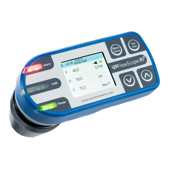
Introduction Product overview VPFlowScope M transmitter Meet the VPFlowScope M transmitter, the 'brains' of the VPFlowScope M. The transmitter is one part of the VPFlowScope M which needs to be combined with a VPSensorCartridge and a safety system. The transmitter features various outputs. Modbus, 4..20 mA, Pulse, USB, Ethernet are all standard. -
Page 8: Vpsensorcartridges
VPFlowScope M probe VPSensorCartridges The VPSensorCartridge includes all sensors to measure flow, pressure and temperature simultaneously. It also includes the calibration characteristics for all available sensors. This makes it possible to exchange the VPSensorCartridge between transmitters or to replace it when calibration is required. -
Page 9: Safety System
Safety system Installation under pressure can be dangerous. Make sure that you understand the safety system before installing the VPFlowScope M probe. The safety system is specially designed for the VPFlowScope M. When the VPSensorCartridge is in the compression fitting and the safety cable is attached, the probe can never exit the compression fitting due to the matching length of the cable. -
Page 10: Quick Start
Find the best point of installation for this product. Make sure that the process conditions are within the specifications of the flow meter For installation of the VPFlowScope M probe, an insertion point needs to be created. You can weld a socket with internal 1/2 inch thread or use a hot tap saddle... -
Page 11: Measurement
Quick start Measurement For all parameters the update interval is 1 second. Within this second, multiple samples are taken and averaged to provide a stable and reliable output. Flow The VPSensorCartridge uses our proprietary insertion type thermal mass flow sensor. There is no bypass flow, which results in a high robustness and less sensitivity for dirt or particles. -
Page 12: Totalizer
VPFlowScope M probe Totalizer The totalizer keeps track of the total consumed amount of compressed air in normal cubic meters, normal liters per minute or in (M)(M)SCF depending on which unit you choose to read out. The refresh interval is 1 second: Actual totalizer data will be available on the display and via the Modbus interfaces. -
Page 13: Mechanical Installation
Prepare the installation The VPFlowScope M probe can be inserted through a welding tap with 1/2 inch female thread or through a hot tap saddle. A hot tap saddle can be installed under pressurized conditions, so there is no need to shut down production. - Page 14 VPFlowScope M probe Installation procedure Insertion depth Generally the insertion depth of the VPFlowScope M probe is 0.5 times the inner pipe diameter, where the bottom of the sensor tip must be in the middle of the pipe (see picture).
-
Page 15: Piping Table
VPFlowScope M probe. The upstream length is the length between the last non- straight object and the VPFlowScope M probe. If the upstream length is straight, and the distortion is downstream of the VPFlowScope probe, you can use the column "downstream length" as a guideline. -
Page 16: Safety System
VPFlowScope M probe Diameter change from Jet shaped flow 40 * D 5 *D small to large (gradual or instant) Diameter change from Flattened flow profile 10 * D 5 * D large to small (gradual change, between 7 and 15 degrees) 1 = inner diameter;... -
Page 17: Assembling And Installing The Instrument
Mechanical installation Assembling and installing the instrument Step 1 Step 2 1. Lift the safety cable 1. Mount the safety line to the 2. Slide the locking ring over the safety cable VPSensorCartridge, it should snap in 3. Place the VPSensorCartridge through the locking completely ring into the compression fitting 2. - Page 18 VPFlowScope M probe Step 5 Step 6 1. Keep the ball valve closed, the probe remains in 1. Keep your hand on top of the instrument. the compression fitting Performing next step will apply force on 2. Check if the safety system is locked the instrument 3.
-
Page 19: Replacing The Vpsensorcartridge
Mechanical installation Replacing the VPSensorCartridge When a VPSensorCartridge needs to be replaced, there is no need to remove the complete assembly. The safety system can be left in place. Step 1 Step 2 1. Unscrew the safety lock 1. Apply pressure on top of the instrument, then 2. - Page 20 VPFlowScope M probe Step 6 Step 5 1. Mount the safety line to the 1. Place the new VPSensorCartridge through the VPSensorCartridge locking ring into the compression fitting 2. Move the locking ring upwards over the VPSensorCartridge Step 7 Step 8 1.
- Page 21 Mechanical installation Step 9 1. Loosen the safety lock and pull the safety line tight 2. Tighten the safety lock 3. Align the flow direction. Alignment by the eye is sufficient © 2016 Van Putten Instruments BV | MAN-VP-SMPR-UK | Revision:1600 | Date:23-03-2016...
-
Page 22: Connectivity
Modbus 4..20mA output The 4..20mA output can be used to connect the VPFlowScope M probe to a control system, a building management system, a multi-meter or any 4..20 mA based SCADA system. The 4..20 mA output is actively powered from the VPFlowScope M. -
Page 23: Pulse Output
Pulses will not be generated until the same amount of positive flow has been added to the totalizer again. In this way we ensure that the pulse output will always be synchronized with the internal totalizer of the VPFlowScope M probe. In case of continuous negative flow, consider to swap the flow meter direction. -
Page 24: Rs485
Pulse output RS485 RS485 is a serial interface that can be used to connect the VPFlowScope M probe to VPVision, remote monitoring software or a building management system. It is important to match the communication parameters. All devices need to speak the same "language". -
Page 25: Ethernet
7.6.2 Modbus TCP Modbus TCP can be used to connect the VPFlowScope M probe to a building management system. When connecting to a building management system, it's important to match the Ethernet settings. The Ethernet settings can be changed with VPStudio 2.0, the built in web server or by using the key pad. -
Page 26: Display
VPFlowScope M probe Display The display enables you to read measurement data in real time. In combination with the keypad, it can also be used to change the most common parameters, see chapter 7.7.4 menu for all available menu options 7.7.1... -
Page 27: Keypad
Connectivity 7.7.3 Keypad The key pad contains 4 buttons to control the display. Menu / Enter Used to enter the (sub)menu or to confirm a setting Escape / Record Will start a data logging session when in the data acquisition Will return from a (sub)menu when not in the data acquisition Button up Navigate up in the menu... - Page 28 VPFlowScope M probe 1 Settings The settings menu can be used to change both functional parameters as display settings. 1.1 Diameter The VPSensorCartridge needs to know the exact inner pipe diameter to calculate mass flow. Changing the diameter is only possible when the sensor is connected. When the menu is entered, first select the desired unit, this can be in mm or inch.
- Page 29 2.1 Change mode The VPFlowScope M probe features 2 different data logging modes. Select the desired mode. Changing the data logger mode will remove all stored data. 2.2 Start/stop session (This option is only available when in multi-session mode) The session will be started when you push the enter button after selecting this option.
-
Page 30: Data Logger
VPFlowScope M probe 3.3 Boundaries Set upper and/or lower boundaries for alarm triggers 3.4 Period Set the hold and reset period for alarm events 3.5 Reset Reset the alarm counter. The alarm counter can only be reset to zero. 4 Info/about This option shows all general information of the transmitter and the VPSensorCartridge, if connected. - Page 31 Connectivity Alarm The VPFlowScope M has a built-in alarm module. The input for an alarm is one of the available measurement values. The unit for this value can be selected as desired. The selected input will be compared to the configured boundaries. Boundaries and modes 2 boundaries are available: Upper boundary...
- Page 32 VPFlowScope M probe Modbus Introduction to Modbus For new users, a complete introduction on the Modbus standard can be found on www.modbus.org. See the document Modbus_over_serial_line_V1_02.pdf, which can be downloaded from their website. We strongly recommend to download and read this information carefully.
- Page 33 Modbus 0072 - 0073 114 - 115 Flow l /min Floating point Read 0074 - 0075 116 - 117 Flow l /sec Floating point Read 0076 - 0077 118 - 119 Flow SCFM Floating point Read 0082 - 0083 130 - 131 Flow m /sec 32-bit integer...
- Page 34 VPFlowScope M probe 0117 - 0118 279 - 280 32-bit integer Read Totalizer negative m 0119 - 011A 281 - 282 Totalizer MSCF 32-bit integer Read 011B - 011C 283 - 284 Totalizer positive MSCF 32-bit integer Read 011D - 011E...
- Page 35 Modbus Available write operations Option Data Description Analogue output mode 4..20 mA mode Pulse mode Alarm mode Other 4..20 mA mode 4..20mA and alarm unit /sec sfps /min /sec /min /sec SCFM °C °F Other /sec Alarm mode Alarm off Alarm on low boundary Alarm on high boundary Alarm on both boundaries...
- Page 36 DAMAGE TO THE ELECTRONICS. THE INSTRUMENT MIGHT BE DAMAGED BEYOND REPAIR. CONNECT THE M12 CONNECTOR BEFORE POWERING UP THE INSTRUMENTS. The VPFlowScope M probe main plug is a M12 5-pin connector which contains the power input, an analogue output and a Modbus interface. Signal Wire color +12...24 VDC...
- Page 37 Electrical connections Example: Input voltage Required maximum current 20mA 24V / 0.02A = 1200 Ohm 1200 Ohm is the maximum load that can be applied with a 24V input level. Above example does not include the current consumption of the flow meter itself. When power to the flow meter is applied using a long cable, include a current consumption of 500mA to the formula.
- Page 38 VPFlowScope M probe 10.3 Alarm The alarm output is an active non potential free output.This means that the + wire is shared between power supply and the alarm output. The idle current will be 0mA. When an alarm is triggered, the alarm output will go to 20mA.
- Page 39 Electrical connections should be done to limit the common mode voltage that can be impressed on the slaves inputs. The required cable quality depends on the total cable distance, the number of nodes and the environmental influences. A local contractor can help you select the right cable for your application. Termination resistor Termination resistors reduce electrical noise sensitivity.
- Page 40 Wire color White / Orange White / Green Orange Green M12 4-pin female connector We offer 2 types of cables for connecting your VPFlowScope M probe to the Ethernet. Connectors Description M12 to M12 Extension cord M12 to RJ45 Connection to routers or switches Cables are available in different lengths.
-
Page 41: Vpstudio Software
Electrical connections VPStudio software The VPFlowScope M transmitter can be read out and configured with the VPStudio 2.0 software. This software can be downloaded from www.vpinstruments.com. VPStudio 2.0 is available for Windows and has been tested on version: XP, 7, 8 and 10, A quick start is shown below, read the VPStudio 2.0 manual for more information. -
Page 42: Exchanging Cartridges
VPFlowScope M probe Exchanging cartridges With the patented VPSensorCartridge concept, traditional re-calibration is something of the past. From now on, you simply exchange the VPSensorCartridge, and continue your measurements with nearly zero downtime. All settings are stored in the VPFlowScope M transmitter and are automatically transferred to the VPSensorCartridge. -
Page 43: Specifications Transmitter
Exchanging cartridges Specifications transmitter Please always check the label of your product for the specifications. Specifications are subject to change as we are continuously improving our products. Please contact us to obtain the latest specification sheet. Sensor interface VPSensorCartridge Proprietary interface, rotational 360 degrees Display Display type 1.8"... -
Page 44: Specifications Vpsensorcartridge
VPFlowScope M probe Specifications VPSensorCartridge Please always check the label of your product for the specifications. Specifications are subject to change as we are continuously improving our products. Please contact us to obtain the latest specification sheet. Flow sensor Measuring principle Thermabridge™... -
Page 45: Order Information And Accessories
Specifications VPSensorCartridge Order information and accessories 15.1 Transmitter Order Code Option Feature VPM.T0001 D000 D010 Display D011 Display + data logger * Availab le models on day of printing Basic features Display features Data logger RS485 3 line display Traditional start/stop 4..20mA, Pulse, Alarm Keypad for configuration Cyclic... -
Page 46: Appendix A - Ul
Lignes directrices pour branchements électriques – UL508 pour le Canada et les États-Unis (voir sur l’étiquettesi le produit est marqué UL) Le VPFlowscope M probe est prévu pour être utilisé avec une source d’alimentation Classe 2 ou avec un transformateur de Classe 2 en accord avec UL1310 ou UL1585. Comme alternative, une source d’alimentation BTCL (Basse Tension Courant Limité) avec les propriétés suivante peut être utilisée :... -
Page 47: Appendix B - Federal Communications Commission (Fcc) Statement
Appendix A - UL Appendix B - Federal Communications Commission (FCC) Statement An FCC grant of equipment authorization and an FCC ID are not required, but the equipment complies with FCC technical requirements. © 2016 Van Putten Instruments BV | MAN-VP-SMPR-UK | Revision:1600 | Date:23-03-2016... - Page 48 www.vpinstruments.com Improve Measure Manage VPInstruments MAN-VP-SMPR-UK-1600 Buitenwatersloot 335 2614 GS Delft Date:23-03-2016 The Netherlands...
Need help?
Do you have a question about the VPFlowScope M probe and is the answer not in the manual?
Questions and answers