
Related Manuals for VP instruments VPLog-i-R


Summary of Contents for VP instruments VPLog-i-R
- Page 1 VPINSTRUMENTS.COM VPLog-i-R User manual © 2020 Van Putten Instruments BV MAN-VP-LOGR-UK-2001 Date: 01-10-2020...
- Page 2 VPLog-i-R © 2020 Van Putten Instruments BV Al l ri ghts res erved. No pa rts of thi s document ma y be reproduced i n a ny form or by a ny mea ns - gra phi c, el ectroni c, or mecha ni ca l , i ncl udi ng photocopyi ng, recordi ng, ta pi ng, or i nforma ti on s tora ge a nd retri eva l s ys tems - wi thout the wri tten permi s s i on of the publ i s her.
-
Page 3: Table Of Contents
Table of Contents 1 Introduction 2 Safety Regulations 3 Instrument Description 4 Installation 5 Connection 6 Configuration 7 Specifications... -
Page 4: Introduction
Introduction This document describes the user manual and the functional specifications of the VPLog-i-R current sensor. Glossary Alternating current Crest Factor = Peek_current/RMS_current Direct current Ground Hertz IDEP/CN8 Combined Nomenclature code milli Ampère Parts pro million; 1ppm=0,0001%=1/1000000 power true RMS true Root Mean Square, Urms = sqrt(mean(U²)) -
Page 5: Safety Regulations
Safety Regulations Warnings, cautions and notes within this manual will be used as follows: WARNING: Used to denote a danger to personnel of serious injury and/or death. The warning will be preceded by the caption WARNING and the detail of any warning will be in bold and uppercase. CAUTION: Used to denote a possibility of damage to material or equipment but not a danger to personnel. -
Page 6: Instrument Description
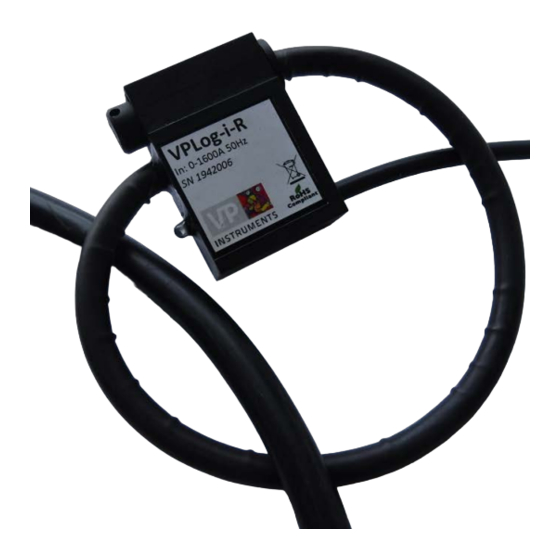
Instrument Description The VPLog-i-R AC current sensor, based on a Rogowski coil, that measures AC currents up to 1600A true-rms on a single phase power cable. The sensor has a modbus interface for communication. The sensor has an indication LED. This blinks when modbus communication is ongoing. -
Page 7: Installation
Connection to the cable To install the VPLog-i-R sensor, wrap the measurement coil around the single phase power cable (L1, L2, L3 or N). Then click the plug into the clamp. The coil has to make a closed loop around the power cable. -
Page 8: Connection
(E.G DISCONNECT POWER, WEAR SAFETY GLASSES, RUBBER GLOVES AND ADEQUATE CLOTHES, ETC) Power-On/Off The VPLog-i-R sensor has no power on/off switch. Applying power to the sensor starts its internal power-up sequence. Switch the sensor off by removing its power supply. Connection... - Page 9 When addressing registers, the command contains the address minus 1, for instance registers 1..3 are addressed as 0..2. The VPLog-i-R also supports the modbus scan protocol. This allows to change the modbus settings and to request extra information from the module.
-
Page 10: Configuration
I RMS (5000 -> 50.00Hz) 73 CB Configuration In order to configure the modbus settings of the VPLog-i-R, connect it to the M12 5 Pin female connector (VPA.0000.300) and use the VPFlowScope JB5 interface KIT (VPA.5001.205) to connect it to your PC. - Page 11 Electrical Specification Unit Min. Typ. Max. Conditions Voltage (PWR to GND) Power consumption Vdc=24V Current range (CF=2) 1600 Current range (CF=1.5) 2200 Frequency range Measurement bandwidth Noise % full scale Supply coefficient ppm/V Temperature coefficient ppm/°C Accuracy % full scale Modbus start-up time Measurement start-up time...
- Page 12 © 2020 Van Putten Instruments BV | MAN-VP-LOGR-UK | Revision: 2001 | Date: 01-10-2020...
- Page 13 Notes © 2020 Van Putten Instruments BV | MAN-VP-LOGR-UK | Revision: 2001 | Date: 01-10-2020...
- Page 14 VPLog-i-R Notes © 2020 Van Putten Instruments BV | MAN-VP-LOGR-UK | Revision: 2001 | Date: 01-10-2020...
- Page 15 easy insight into energy flows VPInstruments Buitenwatersloot 335 2614 GS Delft The Netherlands info@vpinstruments.com www.vpinstruments.com MAN-VP-LOGR-UK-2001 Date: 01-10-2020...
Need help?
Do you have a question about the VPLog-i-R and is the answer not in the manual?
Questions and answers