Table of Contents
Advertisement
Quick Links
F04.07
Version 1.0
Publication date 24-06-2024
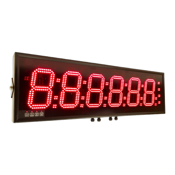
Model FUSION-S
Installation & Operating Manual
Easy setup
Addressable
Flexible String Extraction
Can Totalise Numeric Strings
Optional Output 4-20mA / 0-10V isolated
Optional Alarm output = 2 or 4 relays
Optional Comms Output = RS232 or RS485
95-230V AC or 11-30V DC power
Caution: There is a risk of electrical shock if this instrument is
not properly installed
Caution: Risk of danger: Read the whole manual before you
install this meter
www.london-electronics.com
Revision 26
!
Advertisement
Table of Contents

Related Manuals for London Electronics FUSION-S


Summary of Contents for London Electronics FUSION-S
- Page 1 Model FUSION-S Installation & Operating Manual Revision 26 Easy setup Addressable Flexible String Extraction Can Totalise Numeric Strings Optional Output 4-20mA / 0-10V isolated Optional Alarm output = 2 or 4 relays Optional Comms Output = RS232 or RS485 95-230V AC or 11-30V DC power...
-
Page 2: Table Of Contents
FUSION-S Users Manual Table of Contents Warranty ..............................1 Warnings ..............................2 Introduction............................3 General Description ..........................4 Suspension Mounting Dimensions......................5 Wall Mounting Dimensions........................6 Panel Mounting Dimensions ........................7 Connections............................8 Connections............................9 Installation Hints For Best Performance ...................10 48V AC Power Wiring Option ......................12 Display Brightness ..........................13 Display Modes .............................14... - Page 3 FUSION-S Users Manual Reverse Display Function (Mirror Image) ..................25 Bootup Routine & Tare Save Choices ....................26 Multi-Program Memory Option ‘MEM’ ....................27 Error Codes & Fault Findings......................28 How To Install Option Boards ......................29 Waste Electrical Electronic Equipment (WEEE) ................30 Equipment Specifications........................31 Record of Revisions..........................32...
-
Page 4: Warranty
FUSION-S Users Manual Warranty We warrant this product against defects in materials or workmanship for a period of three (3) years from the date of purchase. In the event of a defect during the warranty period, the unit should be returned, freight (and all duties and taxes) prepaid by the Buyer to the authorised distributor from where the unit was purchased. -
Page 5: Warnings
FUSION-S Users Manual Warnings Please carefully read this manual and all warnings. Install the meter ONLY when you are sure that you’ve covered all aspects. Where the product is intended for “UL” installations, removal or addition of option boards is not permitted. -
Page 6: Introduction
FUSION-S Users Manual Introduction Please contact us if you need help, if you have a complaint, or if you have suggestions to help us improve our products or services. If you contact us about a product you already have, please tell us the full model number and serial number, so that we can give you accurate and fast help. -
Page 7: General Description
FUSION-S Users Manual General Description This series of meters accepts industrial sensors to allow various physical measurements to be made, such a weight, temperature, pressure, humidity etc. Different models are available for different sensor types. The main function of this series is to give a numeric readout of the variable being monitored. -
Page 8: Suspension Mounting Dimensions
FUSION-S Users Manual Suspension Mounting Dimensions 15mmO 15mmO 6.35mmO 6.35mmO Plan View 25mm X mm Y mm Short-drop mounting holes Long-drop mounting holes W mm 77 mm 8.8.8.8.8.8. H mm H mm 25mm Cable Glands. Number of glands depends on installed options. -
Page 9: Wall Mounting Dimensions
FUSION-S Users Manual Wall Mounting Dimensions 98 mm W mm 22mm 60 mm 8.8.8.8.8.8. H mm 25mm Cable Glands. Number of glands depends on installed options. 80 mm 60 mm The 4 bracket holes are 5.2mm diameter 60 mm X mm 72.5 mm... -
Page 10: Panel Mounting Dimensions
FUSION-S Users Manual Panel Mounting Dimensions 67mm 8.8.8.8.8.8. 25mm H mm A mm Neoprene Bezel W mm gasket Neoprene Cable glands gasket B mm Detail showing bracket hardware fitting sequence Bezel Panel cutout dimensions Neoprene gasket Panel A+3mm(h) x B+3mm(w) -
Page 11: Connections
FUSION-S Users Manual Warning: Connections Disconnect all power before removing the rear of the display There is a wide range of possible locations for the input board, output board and power supply board/s. Their locations depend on the height of digits, number of digits, brightness of digits and any installed options. -
Page 12: Connections
FUSION-S Users Manual Connections Warning: Disconnect all power before removing the rear of the display Output option board (if fitted) Connectors and options Analog Connectors may be Serial Data 0, 2 or 4 Alarm Relay output present even if output... -
Page 13: Installation Hints For Best Performance
FUSION-S Users Manual Installation Hints For Best Performance This section offers several suggestions which will help you get the best performance from your system. RS232 and RS485 use comparatively small signals which can easily be corrupted by the potentially high level of electrical noise which can be created by electrical machinery such as motors, welding systems, discharge lighting, AC power inverters and solenoids. - Page 14 FUSION-S Users Manual Page 11 www.london-electronics.com...
-
Page 15: 48V Ac Power Wiring Option
FUSION-S Users Manual 48V AC Power Wiring Option Page 12 www.london-electronics.com... -
Page 16: Display Brightness
FUSION-S Users Manual Display Brightness You can adjust the display brightness at any time, provided the display is locked. Set1 Set2 Output Alarms Digit Lockout Switch must be ON Max/Min Reset Circuit board Press 3 seconds briGHT Set1 Set2 Output... -
Page 17: Display Modes
FUSION-S Users Manual Display Modes You can choose from three operating modes. Set1 Set2 Output Alarms Lockout Switch must be OFF Digit Max/Min Reset Circuit board Press 3 seconds Set2 Output ASCII quant Set1 Alarms Display shows Digit qua.tot Max/Min... -
Page 18: Serial Data Settings
FUSION-S Users Manual Serial Data Settings Choose the serial data settings to suit the transmitting device. Set2 Output Set1 Alarms Lockout Switch must be OFF Digit Max/Min Reset Press 3 seconds Circuit board Display shows each of the parameters Set1... -
Page 19: Serial Data Setting Examples
FUSION-S Users Manual Serial Data Setting Examples Sending data to an addressed display Let us assume the display has address 45 and you want to send the value 123.4 to it at 19200 baud. Your data will be sent as <STX>45123.4<CR>... -
Page 20: Ascii Hex Codes & Displayed Characters
FUSION-S Users Manual ASCII Hex Codes & Displayed Characters 20 space Other ASCII Hex codes and their characters are:- Hex Function Hex Function Line Feed Form Feed < Carriage Return > Escape Space ‘ & Page 17 www.london-electronics.com... -
Page 21: Signal Levels
FUSION-S Users Manual Signal Levels These examples show a single ASCII character 2C (0010 1100) which is a Comma, so that you can see the voltages in RS485 and RS232 systems. Typical UART output 40 80 Idle Start Stop RS485 data line levels 8n1... -
Page 22: Logic Input Functions
FUSION-S Users Manual Logic Input Functions The three contact closure inputs on the rear of the meter have default functions which are:- Contact closure 1 = Tare Contact closure 2 = Peak/Valley display Contact closure 3 = Reset You can re-assign these to include: HOLD, Nett/Gross value display, Memory... -
Page 23: Logic Input Connections & Front Buttons
FUSION-S Users Manual Logic Input Connections & Front Buttons The previous page explained how to select the functions of the 3 logic inputs. You can connect remote contact closures or open NPN collectors to activate these logic inputs. The logic input provides a 5V DC signal. When you connect this to common, a current of 1mA will flow. -
Page 24: Factory Defaults
FUSION-S Users Manual Factory Defaults You can return the display to its factory default conditions whenever you wish. If you do so, you will permanently loose all your settings and will need to start from the beginning again. The calibration Audit Counter will NOT be reset, there is no way provided to reset this value, as it is intended as a secure record to indicate whether changes have been made to the display since it was last calibrated.. -
Page 25: Scale Factor Adjustment
FUSION-S Users Manual Scale Factor Adjustment After you have calibrated your meter, you can use the SCALE feature to make fine adjustments to calibration, without affecting the calibration itself. Example Changing volume units of measure from litres to Imperial gallons You could also use the SCALE to convert your readout from litres to imperial gallons, with- out affecting the calibration. -
Page 26: Offset Adjustment
FUSION-S Users Manual Offset Adjustment OFf.SeT After you have calibrated your meter, you can use the feature to make fine additions or subtractions to the reading, without affecting the calibration itself. Set1 Set2 Output Alarms Digit Max/Min Reset Lockout Switch must be OFF... -
Page 27: Menu Timeout Adjustment
FUSION-S Users Manual Menu Timeout Adjustment The display has a default timeout of 60 seconds, to allow you sufficient time to refer to the manual between key operations. You can make this period shorter, if you wish, once you become more familiar with the setup method. -
Page 28: Reverse Display Function (Mirror Image)
FUSION-S Users Manual Reverse Display Function (Mirror Image) If you need to be able to see a reflection of the display in a mirror or other reflective surface, for example in a simple heads-up system, or for drivers reversing into a bay, using mirrors only, you can set the display to show as a mirror image. -
Page 29: Bootup Routine & Tare Save Choices
FUSION-S Users Manual Bootup Routine & Tare Save Choices When you switch on your meter, it can be set to power up with 3 possible summary message combinations. The choices are:- boot 0 = Segment test, followed by a full summary of software revision, calibration audit number, model number, installed options. -
Page 30: Multi-Program Memory Option 'Mem
FUSION-S Users Manual Multi-Program Memory Option ‘MEM’ The three contact closure inputs on the rear of the meter may be used to call up between 1 to 7 additional meter setup memories (pages), if the MEM option has been installed. -
Page 31: Error Codes & Fault Findings
If the Green LED is on, but no flickering of the red is seen, check that the data source has been set to transmit permanently. If the data source is another London Electronics Display, make sure it has been set to mode C1 and that the enable terminal on the serial output connector is connected to data common. -
Page 32: How To Install Option Boards
FUSION-S Users Manual How To Install Option Boards Warning: Disconnect Where the product is intended for “UL” installations power before you expose removal or addition of option boards is not permitted. the internals of the display If you want to open your display to install or modify option boards, follow these steps... -
Page 33: Waste Electrical Electronic Equipment (Weee)
FUSION-S Users Manual Waste Electrical Electronic Equipment (WEEE) In Europe, this equipment must be disposed of in accordance with European parliamentary Directive 2002/96/EC This directive encourages recycling and the reduction of waste materials in the environment. This means it must be sent to an approved recycling plant if you want to dispose of it. -
Page 34: Equipment Specifications
FUSION-S Users Manual Equipment Specifications RS232 / RS485 / RS422 Page 31 www.london-electronics.com... -
Page 35: Record Of Revisions
FUSION-S Users Manual Record of Revisions 6 September 2010 Version F00.18 Software released. Manual format revised to improve clarity and segregate easy from advanced menu functions. Optional outputs now described in their own dedicated manuals. DIN Rail mounting option added. -
Page 36: Declaration Of Uk & Ce Conformity
Signal cabling shall be routed separately to power carrying cabling (includes relay output wiring) All signal cabling shall be screened. The screen shall only be terminated to the power earth terminal at the meter end of the cable. Declared as true and correct, for and on behalf of London Electronics Ltd. J.R.Lees Director Page 33 www.london-electronics.com...
Need help?
Do you have a question about the FUSION-S and is the answer not in the manual?
Questions and answers