Table of Contents
Advertisement
R-410A
ZF SERIES
3 - 6 Ton
60 Hertz
General . . . . . . . . . . . . . . . . . . . . . . . . . . . . . . . . . . . . . . . . . . 2
Installation . . . . . . . . . . . . . . . . . . . . . . . . . . . . . . . . . . . . . . . . 5
Installation Safety Information. . . . . . . . . . . . . . . . . . . . . . . 5
Limitations . . . . . . . . . . . . . . . . . . . . . . . . . . . . . . . . . . . . . . 5
Location. . . . . . . . . . . . . . . . . . . . . . . . . . . . . . . . . . . . . . . . 7
Rigging And Handling . . . . . . . . . . . . . . . . . . . . . . . . . . . . . 7
Ductwork . . . . . . . . . . . . . . . . . . . . . . . . . . . . . . . . . . . . . . 12
Condensate Drain . . . . . . . . . . . . . . . . . . . . . . . . . . . . . . . 12
Compressors. . . . . . . . . . . . . . . . . . . . . . . . . . . . . . . . . . . 12
Filters . . . . . . . . . . . . . . . . . . . . . . . . . . . . . . . . . . . . . . . . 13
Power And Control Wiring. . . . . . . . . . . . . . . . . . . . . . . . . 13
Optional Electric Heat . . . . . . . . . . . . . . . . . . . . . . . . . . . . 38
Options/Accessories . . . . . . . . . . . . . . . . . . . . . . . . . . . . . 41
Checking Supply Air CFM . . . . . . . . . . . . . . . . . . . . . . . . . 50
Operation . . . . . . . . . . . . . . . . . . . . . . . . . . . . . . . . . . . . . . . 51
1 ZF036-072 Unit Limitations . . . . . . . . . . . . . . . . . . . . . . . . 6
2 Weights and Dimensions . . . . . . . . . . . . . . . . . . . . . . . . . 8
3 ZF036-072 Unit Accessory Weights . . . . . . . . . . . . . . . . . 8
4 ZF036-072 Unit Clearances . . . . . . . . . . . . . . . . . . . . . . 10
5 ZF036-072 Utilities Entry . . . . . . . . . . . . . . . . . . . . . . . . . 11
6 Control Wire Sizes . . . . . . . . . . . . . . . . . . . . . . . . . . . . . . 14
7 Electrical Data . . . . . . . . . . . . . . . . . . . . . . . . . . . . . . . . . 16
8 ZF036-072 Physical Data . . . . . . . . . . . . . . . . . . . . . . . . 34
9 Electric Heat Minimum Supply Air . . . . . . . . . . . . . . . . . . 38
10 Gas Heat Application Data . . . . . . . . . . . . . . . . . . . . . . . 38
11 Gas Pipe Sizing - CapacIty of Pipe . . . . . . . . . . . . . . . . . 39
12 Altitude/Temperature Correction Factors . . . . . . . . . . . . 43
13 ZF Blower Performance Side Duct . . . . . . . . . . . . . . . . . 46
14 ZF Blower Performance Bottom Duct . . . . . . . . . . . . . . . 48
15 Belt Drive RPM Selection . . . . . . . . . . . . . . . . . . . . . . . . 49
1 ZF036-072 Component Location . . . . . . . . . . . . . . . . . . . 6
2 Unit 4 Point Load Weight . . . . . . . . . . . . . . . . . . . . . . . . . 8
3 Unit 6 Point Load Weight . . . . . . . . . . . . . . . . . . . . . . . . . 8
4 Center of Gravity . . . . . . . . . . . . . . . . . . . . . . . . . . . . . . . 8
Dimensions . . . . . . . . . . . . . . . . . . . . . . . . . . . . . . . . . . . 9
Dimensions . . . . . . . . . . . . . . . . . . . . . . . . . . . . . . . . . . . 9
Physical Dimensions . . . . . . . . . . . . . . . . . . . . . . . . . . . 10
8 ZF036-072 Disconnect Location . . . . . . . . . . . . . . . . . . 10
9 ZF036-072 Unit Side Duct Openings . . . . . . . . . . . . . . . 11
10 ZF036-072 Roof Curb . . . . . . . . . . . . . . . . . . . . . . . . . . 11
11 Condensate Drain . . . . . . . . . . . . . . . . . . . . . . . . . . . . . 12
12 Compressor Restraining Bracket . . . . . . . . . . . . . . . . . . 13
TABLE OF CONTENTS
Cooling Sequence Of Operation . . . . . . . . . . . . . . . . . . . . 51
No Outdoor Air Options . . . . . . . . . . . . . . . . . . . . . . . . . 51
Cooling Operation Errors . . . . . . . . . . . . . . . . . . . . . . . . 52
Electric Heating Sequence Of Operations. . . . . . . . . . . . . 53
Electric Heat Operation Errors . . . . . . . . . . . . . . . . . . . . 53
Gas Heating Sequence Of Operations . . . . . . . . . . . . . . . 54
Gas Heat Operation Errors . . . . . . . . . . . . . . . . . . . . . . . . 54
Flash Codes . . . . . . . . . . . . . . . . . . . . . . . . . . . . . . . . . . . 55
Resets . . . . . . . . . . . . . . . . . . . . . . . . . . . . . . . . . . . . . . . . 55
Heat Anticipator Setpoints. . . . . . . . . . . . . . . . . . . . . . . . . 55
Start-up (Cooling) . . . . . . . . . . . . . . . . . . . . . . . . . . . . . . . . . 56
Start-up (Gas Heat) . . . . . . . . . . . . . . . . . . . . . . . . . . . . . . . . 56
Checking Gas Input . . . . . . . . . . . . . . . . . . . . . . . . . . . . . . . . 58
Charging The Unit . . . . . . . . . . . . . . . . . . . . . . . . . . . . . . . . . 59
Troubleshooting . . . . . . . . . . . . . . . . . . . . . . . . . . . . . . . . . . . 59
Fan On And Off Delays . . . . . . . . . . . . . . . . . . . . . . . . . . . 66
LIST OF TABLES
16 Indoor Blower Specifications (Belt Drive) . . . . . . . . . . . . 50
17 Power Exhaust Specifications . . . . . . . . . . . . . . . . . . . . . 50
18 Additional Static Resistance . . . . . . . . . . . . . . . . . . . . . . 51
19 Electric Heat Limit Setting . . . . . . . . . . . . . . . . . . . . . . . . 53
20 Electric Heat Anticipator Setpoints . . . . . . . . . . . . . . . . . 54
21 Single Stage Gas Heat Limit Control Setting . . . . . . . . . 55
22 2 Stage Gas Heat Limit Control Setting . . . . . . . . . . . . . 55
23 Gas Heat Anticipator Setpoints . . . . . . . . . . . . . . . . . . . . 56
24 Gas Rate-Cubit Feet per Hour . . . . . . . . . . . . . . . . . . . . 58
25 ZF036 (3.0 Ton) Operating Pressures . . . . . . . . . . . . . . 61
26 ZF048 (4.0 Ton) Operating Pressures . . . . . . . . . . . . . . 61
27 ZF060 (5.0 Ton) Operating Pressures . . . . . . . . . . . . . . 61
28 ZF072 (6.0 Ton) Operating Pressures . . . . . . . . . . . . . . 62
29 Unit Control Board Flash Codes . . . . . . . . . . . . . . . . . . . 66
30 Ignition Control Board Flash Codes . . . . . . . . . . . . . . . . 66
LIST OF FIGURES
13 Typical Field Power and Control Wiring . . . . . . . . . . . . . 15
14 Side Entry Gas Piping . . . . . . . . . . . . . . . . . . . . . . . . . . 39
15 Bottom Entry Gas Piping . . . . . . . . . . . . . . . . . . . . . . . . 39
16 Vent And Combustion Air Hood . . . . . . . . . . . . . . . . . . . 41
17 Enthalpy Set Point Chart . . . . . . . . . . . . . . . . . . . . . . . . 42
18 Honeywell Economizer Control W7212 . . . . . . . . . . . . . 42
19 Belt Adjustment . . . . . . . . . . . . . . . . . . . . . . . . . . . . . . . 42
20 Altitude/Temperature Correction Factors . . . . . . . . . . . . 43
21 Pressure Drop Across Coil . . . . . . . . . . . . . . . . . . . . . . . 50
22 Gas Valve Piping . . . . . . . . . . . . . . . . . . . . . . . . . . . . . . 54
23 Typical Single Stage Gas Valves . . . . . . . . . . . . . . . . . . 57
24 Typical 2 Stage Gas Valves . . . . . . . . . . . . . . . . . . . . . . 57
25 Proper Flame Adjustment . . . . . . . . . . . . . . . . . . . . . . . 57
26 Typical Flame Appearance . . . . . . . . . . . . . . . . . . . . . . 57
27 Unit Control Board . . . . . . . . . . . . . . . . . . . . . . . . . . . . . 66
697890-YIM-C-0213
Advertisement
Table of Contents

Related Manuals for York ZF072


Summary of Contents for York ZF072
-
Page 1: Table Of Contents
13 ZF Blower Performance Side Duct ....46 28 ZF072 (6.0 Ton) Operating Pressures ....62 14 ZF Blower Performance Bottom Duct . -
Page 2: General
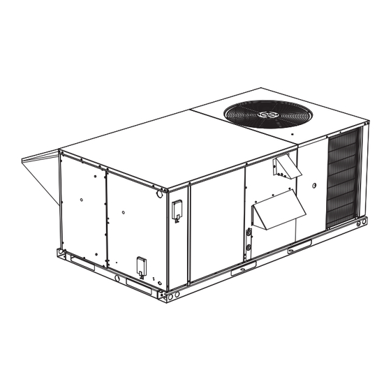
697890-YIM-C-0213 General ® YORK Model ZF units are either single package cooling units equipped with optional factory installed electric heaters, or single This product must be installed in strict compliance with package gas-fired central heating furnaces with cooling unit. the installation instructions and any applicable local, Both are designed for outdoor installation on a rooftop or slab. - Page 3 Renewal Parts accompanying the equipment whenever working on air conditioning equipment. Be sure to follow all other applicable ® Contact your local York parts distribution center for authorized safety precautions and codes including ANSI Z223.1 or CSA- replacement parts. B149.1- latest edition.
- Page 4 048 = 4.0 Ton Simplicity Intelli-Comfort™ Controller w/Simplicity®LINC 060 = 5.0 Ton 072 = 6.0 Ton York Commercial Comfort System (YCCS) Rtu Controller 2" Pleated Filters, MERV 7 BAS Ready Economizer (2-10 V.D.C. Actuator Without a Controller) Heat Type and Nominal Heat Capacity Any Combination of Additional Options that Don’t Have an Option Code Pre-assigned...
-
Page 5: Installation
697890-YIM-C-0213 Installation Limitations These units must be installed in accordance with the following: Installation Safety Information In U.S.A.: Read these instructions before continuing this appliance National Electrical Code, ANSI/NFPA No. 70 - Latest installation. This is an outdoor combination heating and cooling Edition unit. -
Page 6: Zf036-072 Unit Limitations
Unit Limitations Size Unit Voltage Applied Voltage Outdoor DB Temp (Tons) Max (°F) 208/230-1-60 208/230-3-60 ZF036 (3.0) 460-3-60 575-3-60 208/230-1-60 208/230-3-60 ZF048 (4.0) 460-3-60 575-3-60 208/230-1-60 208/230-3-60 ZF060 (5.0) 460-3-60 575-3-60 208/230-3-60 ZF072 460-3-60 (6.0) 575-3-60 Johnson Controls Unitary Products... -
Page 7: Location
If a unit is to be installed on a roof curb other than a ® York roof curb, gasketing must be applied to all Excessive exposure of this furnace to contaminated surfaces that come in contact with the unit underside. -
Page 8: Weights And Dimensions
697890-YIM-C-0213 Front Front Figure 2: Unit 4 Point Load Weight Figure 3: Unit 6 Point Load Weight FRONT LEFT Figure 4: Center of Gravity Table 2: Weights and Dimensions Size Weight (lbs.) Center of Gravity 4 Point Load Location (lbs.) 6 Point Load Location (lbs.) (Tons) Shipping Operating... -
Page 9: Zf036-072 Cooling Only/Electric Heat Front View Physical Dimensions
697890-YIM-C-0213 Figure 5: ZF036-072 Cooling Only/Electric Heat Front View Physical Dimensions Figure 6: ZF036-072 Cooling Only/Gas Heat Front View Physical Dimensions Johnson Controls Unitary Products... -
Page 10: Zf036-072 Unit Clearances
697890-YIM-C-0213 27-1/2 1-5/8 27-1/2 19-3/4 19-1/2 44-7/8 Detail “A” 27-1/2 7-1/4 27-1/2 10-1/4 19-1/8 3-1/2 8-1/4 “A” 44-7/8 LH End View Rear View 4-3/8 Dimension “A” Fixed Outdoor Air Damper Detail “B” Motorized 16-1/2 Damper Figure 7: ZF036-072 Fixed Outdoor Air Motorized Damper Rain Hood Physical Dimensions Table 4: ZF036-072 Unit Clearances Location Clearance... -
Page 11: Zf036-072 Utilities Entry
697890-YIM-C-0213 Figure 9: ZF036-072 Unit Side Duct Openings Table 5: ZF036-072 Utilities Entry Hole Opening Size (Dia.) Used For Side 7/8” KO Control Wiring Bottom Side 2” KO Power Wiring Bottom 1-5/8” KO Gas Piping (Front) 1-1/2” KO Gas Piping (Bottom) 1. -
Page 12: Ductwork
697890-YIM-C-0213 Ductwork Compressors Ductwork should be designed and sized according to the The scroll compressor used in this product is specifically methods in Manual D of the Air Conditioning Contractors of designed to operate with R-410A Refrigerant and cannot be America (ACCA) or as recommended by any other recognized interchanged. -
Page 13: Filters
A disconnect must be utilized for these units. Factory installed Figure 12: Compressor Restraining Bracket disconnects are available. If installing a disconnect (field ® supplied or York International supplied accessory), refer to Figure 8 for the recommended mounting location. Do not loosen compressor mounting bolts. -
Page 14: Control Wire Sizes
697890-YIM-C-0213 Convenience Outlet Power wiring is brought into the unit through the side of the unit or the basepan inside the curb. If a factory option convenience outlet is installed, the weatherproof outlet cover must be field installed. The cover Thermostat Wiring shall be located behind the filter access panel. -
Page 15: Typical Field Power And Control Wiring
697890-YIM-C-0213 TYPICAL POWER WIRING REFER TO THE ELECTRICAL DATA TABLES TO SIZE THE DISCONNECT SWITCH, OVERCURRENT PROTEC- TION AND WIRING. TYPICAL CONTROL WIRING COOLING ONLY (24 VOLT THERMOSTAT) COOLING / HEATING (24 VOLT THERMOSTAT) THERMOSTAT UNIT TERMINAL THERMOSTAT TERMINALS STRIP TB1 TERMINALS UNIT TERMINAL STRIP TB1... -
Page 16: Electrical Data
697890-YIM-C-0213 Table 7: Electrical Data ZF036-060 - Without Powered Convenience Outlet (Belt Drive) OD Fan Supply Compressors Motors Blower Conv Electric Heat Option Fuse Size (each) Volt (each) Motor Outlet Breaker (Tons) (Amps) Size RLA LRA MCC Model Stages Amps (Amps) None 28.3... - Page 17 697890-YIM-C-0213 ZF036-060 - Without Powered Convenience Outlet (Belt Drive) (Continued) OD Fan Supply Compressors Motors Blower Conv Electric Heat Option Fuse Size (each) Volt (each) Motor Outlet Breaker (Tons) (Amps) Size RLA LRA MCC Model Stages Amps (Amps) None 36.3 19.2 36.3 26.9...
- Page 18 697890-YIM-C-0213 ZF072 - Without Powered Convenience Outlet (Belt Drive) Cooling With/Without Electric Heat OD Fan Supply Compressors Motors Blower Conv Electric Heat Option Fuse Size (each) Volt (each) Motor Outlet Breaker (Tons) (Amps) Size RLA LRA MCC Model Stages Amps...
- Page 19 697890-YIM-C-0213 ZF036-060 Without Powered Convenience Outlet (Belt Drive High Static) OD Fan Supply Compressors Motors Blower Conv Electric Heat Option Fuse Size (each) Volt (each) Motor Outlet Breaker (Tons) (Amps) Size RLA LRA MCC Model Stages Amps (Amps) None 28.3 19.2 33.5 26.9...
- Page 20 697890-YIM-C-0213 ZF036-060 Without Powered Convenience Outlet (Belt Drive High Static) (Continued) OD Fan Supply Compressors Motors Blower Conv Electric Heat Option Fuse Size (each) Volt (each) Motor Outlet Breaker (Tons) (Amps) Size RLA LRA MCC Model Stages Amps (Amps) None 28.1 11.1 28.1...
- Page 21 697890-YIM-C-0213 ZF072 - Without Powered Convenience Outlet (Belt Drive High Static) Cooling With/Without Electric Heat OD Fan Supply Compressors Motors Blower Conv Electric Heat Option Fuse Size (each) Volt (each) Motor Outlet Breaker (Tons) (Amps) Size RLA LRA MCC Model...
- Page 22 697890-YIM-C-0213 ZF036-060 Without Powered Convenience Outlet (Direct Drive) OD Fan Supply Compressors Motors Blower Conv Electric Heat Option Fuse Size (each) Volt (each) Motor Outlet Breaker (Tons) (Amps) Size RLA LRA MCC Model Stages Amps (Amps) None 26.7 19.2 31.5 26.9 41.2 208-1-60 14.7...
- Page 23 697890-YIM-C-0213 ZF036-060 Without Powered Convenience Outlet (Direct Drive) (Continued) OD Fan Supply Compressors Motors Blower Conv Electric Heat Option Fuse Size (each) Volt (each) Motor Outlet Breaker (Tons) (Amps) Size RLA LRA MCC Model Stages Amps (Amps) None 36.3 19.2 36.3 26.9 43.2...
- Page 24 697890-YIM-C-0213 ZF072 - Without Powered Convenience Outlet (Direct Drive) Cooling With/Without Electric Heat OD Fan Supply Compressors Motors Blower Conv Electric Heat Option Fuse Size (each) Volt (each) Motor Outlet Breaker (Tons) (Amps) Size RLA LRA MCC Model Stages Amps...
- Page 25 697890-YIM-C-0213 ZF036-060 - With Powered Convenience Outlet (Belt Drive) OD Fan Supply Max Fuse Compressors Motors Blower Conv Electric Heat Option Size Breaker (each) Volt (each) Motor Outlet (Tons) (Amps) Size RLA LRA MCC Model Stages Amps (Amps) None 38.3 19.2 46.0 26.9...
- Page 26 697890-YIM-C-0213 ZF036-060 - With Powered Convenience Outlet (Belt Drive) (Continued) OD Fan Supply Max Fuse Compressors Motors Blower Conv Electric Heat Option Size Breaker (each) Volt (Tons) (each) Motor Outlet (Amps) Size (Amps) RLA LRA MCC Model Stages Amps None 46.3 19.2 46.3...
- Page 27 697890-YIM-C-0213 ZF072 - With Powered Convenience Outlet (Belt Drive) Cooling With/Without Electric Heat OD Fan Supply Compressors Motors Blower Conv Electric Heat Option Fuse Size (each) Volt (each) Motor Outlet Breaker (Tons) (Amps) Size RLA LRA MCC Model Stages Amps...
- Page 28 697890-YIM-C-0213 ZF036-060 With Powered Convenience Outlet (Belt Drive High Static) OD Fan Supply Max Fuse Compressors Motors Blower Conv Electric Heat Option Size Breaker (each) Volt (each) Motor Outlet (Tons) (Amps) Size RLA LRA MCC Model Stages Amps (Amps) None 38.3 19.2 46.0...
- Page 29 697890-YIM-C-0213 ZF036-060 With Powered Convenience Outlet (Belt Drive High Static) (Continued) OD Fan Supply Max Fuse Compressors Motors Blower Conv Electric Heat Option Size Breaker (each) Volt (Tons) (each) Motor Outlet (Amps) Size (Amps) RLA LRA MCC Model Stages Amps None 38.1 11.1...
- Page 30 697890-YIM-C-0213 ZF072 - With Powered Convenience Outlet (Belt Drive High Static) Cooling With/Without Electric Heat OD Fan Supply Compressors Motors Blower Conv Electric Heat Option Fuse Size (each) Volt (each) Motor Outlet Breaker (Tons) (Amps) Size RLA LRA MCC Model...
- Page 31 697890-YIM-C-0213 ZF036-060 With Powered Convenience Outlet (Direct Drive) OD Fan Supply Max Fuse Compressors Motors Blower Conv Electric Heat Option Size Breaker (each) Volt (each) Motor Outlet (Tons) (Amps) Size (Amps) RLA LRA MCC Model Stages Amps None 36.7 19.2 44.0 26.9 53.7...
- Page 32 697890-YIM-C-0213 ZF036-060 With Powered Convenience Outlet (Direct Drive) (Continued) OD Fan Supply Max Fuse Compressors Motors Blower Conv Electric Heat Option Size Breaker (each) Volt (each) Motor Outlet (Tons) (Amps) Size (Amps) RLA LRA MCC Model Stages Amps None 46.3 19.2 46.3 26.9...
- Page 33 697890-YIM-C-0213 ZF072 - With Powered Convenience Outlet (Direct Drive) Cooling With/Without Electric Heat OD Fan Supply Compressors Motors Blower Conv Electric Heat Option Fuse Size (each) Volt (each) Motor Outlet Breaker (Tons) (Amps) Size RLA LRA MCC Model Stages Amps...
-
Page 34: Zf036-072 Physical Data
697890-YIM-C-0213 Table 8: ZF036-072 Physical Data ZF036-060 Physical Data Models Component ZF036 ZF048 ZF060 Nominal Tonnage AHRI COOLING PERFORMANCE Gross Capacity @ AHRI A point (Btu) 37000 49300 59000 AHRI net capacity (Btu) 35500 47500 56500 11.0 11.0 10.8 SEER 13.0 13.0 13.0... - Page 35 697890-YIM-C-0213 ZF036-060 Physical Data (Continued) Models Component ZF036 ZF048 ZF060 Nominal Tonnage CONDENSER FAN DATA Quantity Fan diameter (Inch) Type Prop Prop Prop Drive type Direct Drive Direct Drive Direct Drive Quantity of motors Motor HP each No. speeds 1090 1090 1090 Nominal total CFM...
- Page 36 697890-YIM-C-0213 ZF072 Physical Data Models Component ZF072 Nominal Tonnage AHRI COOLING PERFORMANCE Gross Capacity @ AHRI A point (Btu) 70360 AHRI net capacity (Btu) 68000 11.2 / 11.0 IEER 11.3 Nominal CFM 2000 System power (KW) 6.07 Refrigerant type R-410A...
- Page 37 697890-YIM-C-0213 ZF072 Physical Data (Continued) Models Component ZF072 Nominal Tonnage CONDENSER FAN DATA Quantity Fan diameter (Inch) Type Prop Drive type Direct Drive No. speeds Number of motors Motor HP each 1100 1090 Nominal total CFM 4200 4200 BELT DRIVE EVAP FAN DATA...
-
Page 38: Optional Electric Heat
697890-YIM-C-0213 Optional Electric Heat These CSA approved heaters are located within the central compartment of the unit with the heater elements extending in The factory or field installed heaters are wired for single point to the supply air chamber. power supply. Power supply need only be brought into the Fuses are supplied, where required, by the factory. -
Page 39: Gas Pipe Sizing - Capacity Of Pipe
697890-YIM-C-0213 Gas Piping NOTE: Maximum capacity of pipe in cubic feet of gas per hour based upon a pressure drop of 0.3 inch W.C. and 0.6 Proper sizing of gas piping depends on the cubic feet per hour specific gravity gas. of gas flow required, specific gravity of the gas and the length of run. - Page 40 697890-YIM-C-0213 The pressure drop in the lines between regulators and between the second stage regulator and the appliance. Pipe size required will depend on the length of the pipe run and the total load of all appliances. FIRE OR EXPLOSION HAZARD Complete information regarding tank sizing for vaporization, Failure to follow the safety warning exactly could result recommended regulator settings, and pipe sizing is available...
-
Page 41: Options/Accessories
697890-YIM-C-0213 Extreme care must be exercised in turning all set point, maximum and minimum damper positioning adjustment screws to prevent twisting them off. Minimum Position Adjustment • Check that the damper blades move smoothly without binding; carefully turn the Minimum Position Adjust screw (found on the damper control module) fully clockwise and Figure 16: Vent And Combustion Air Hood then set the thermostat indoor fan switch to the ON... -
Page 42: Enthalpy Set Point Chart
697890-YIM-C-0213 the actuator modulates from the minimum position to the full Phasing open position based on the highest call from either the mixed ZF units are properly phased at the factory. Check for proper air sensor input or the AQ voltage input. compressor rotation. -
Page 43: Altitude/Temperature Correction Factors
697890-YIM-C-0213 CFM Static Pressure and Power-Altitude and Temperature Corrections The information below should be used to assist in application of Procedure for adjusting belt tension: product when being applied at altitudes at or exceeding 1000 feet above sea level. 1. Loosen six nuts (top and bottom) A. 2. - Page 44 697890-YIM-C-0213 The examples below will assist in determining the airflow blower tables to select the blower speed and the BHP performance of the product at altitude. requirement. Example 1: What are the corrected CFM, static pressure, and Solution: As in the example above, no temperature BHP at an elevation of 5,000 ft.
- Page 45 697890-YIM-C-0213 Drive Selection Determine side or bottom supply air duct application. Determine desired airflow. Calculate or measure the amount of external static pressure. Using the operating point determined from steps 1, 2 & 3, locate this point on the appropriate supply air blower performance table. (Linear interpolation may be necessary.) Noting the RPM and BHP from step 4, locate the appropriate motor and/or drive on the RPM selection table.
-
Page 46: Zf Blower Performance Side Duct
697890-YIM-C-0213 Table 13: ZF Blower Performance Side Duct ZF036 (3 Ton Belt Drive) Side Duct Available External Static Pressure - IWG Air Flow (CFM) RPM BHP RPM BHP RPM BHP RPM BHP RPM BHP RPM BHP RPM BHP RPM BHP RPM BHP RPM BHP Field Supplied Drive Standard Drive Option HIgh Static Drive Option... - Page 47 697890-YIM-C-0213 ZF072 (6 Ton Belt Drive) - Side Duct Available External Static Pressure - IWG Air Flow (CFM) RPM BHP RPM BHP RPM BHP RPM BHP RPM BHP RPM BHP RPM BHP RPM BHP RPM BHP RPM BHP Field Supplied Drive...
-
Page 48: Zf Blower Performance Bottom Duct
697890-YIM-C-0213 Table 14: ZF Blower Performance Bottom Duct ZF036 (3 Ton Belt Drive) Bottom Duct Available External Static Pressure - IWG Air Flow (CFM) RPM BHP RPM BHP RPM BHP RPM BHP RPM BHP RPM BHP RPM BHP RPM BHP RPM BHP RPM BHP Field Supplied Drive Standard Drive Option HIgh Static Drive Option... -
Page 49: Belt Drive Rpm Selection
697890-YIM-C-0213 ZF072 (6 Ton Belt Drive) Bottom Duct Available External Static Pressure - IWG Air Flow (CFM) RPM BHP RPM BHP RPM BHP RPM BHP RPM BHP RPM BHP RPM BHP RPM BHP RPM BHP RPM BHP Field Supplied Drive... -
Page 50: Checking Supply Air Cfm
697890-YIM-C-0213 Table 16: Indoor Blower Specifications (Belt Drive) Motor Motor Sheave Blower Sheave Size Datum Dia. Datum Dia. Belt (Tons) Eff. Frame Bore (in.) Model Bore (in.) Model (in.) (in.) 1-1/2 1725 1.15 2.8 - 3.8 1VL44 AK64 (3.0) 1-1/2 1725 1.15 4.0 - 5.0... -
Page 51: Operation
697890-YIM-C-0213 Table 18: Additional Static Resistance Electric Heat kW Size Cooling Only Economizer (Tons) 7 - 15 20 - 30 1000 0.08 0.07 0.04 0.06 1200 0.10 0.08 0.05 0.07 1400 0.12 0.09 0.06 0.08 1600 0.14 0.11 0.07 0.09 036 (3.0) 1800 0.16... -
Page 52: Cooling Operation Errors
697890-YIM-C-0213 Economizer With Dual Enthalpy Sensors Should a low-pressure switch open three times within one hour of operation, the UCB will lock-out the compressor and flash a The operation with the dual enthalpy sensors is identical to the code (Table 29). single sensor except that a second enthalpy sensor is mounted in the return air. -
Page 53: Electric Heating Sequence Of Operations
697890-YIM-C-0213 Compressor Protection This limit is monitored regardless of unit operation status, i.e. the limit is monitored at all times. In addition to the external pressure switches, the compressor also has inherent (internal) protection. If there is an abnormal If the temperature limit opens three times within one hour, it will temperature rise in a compressor, the protector will open to shut lock-on the indoor blower motor and a flash code is initiated down the compressor. -
Page 54: Gas Heating Sequence Of Operations
697890-YIM-C-0213 Electric Heat Anticipator Setpoints Redundant valve Main valve It is important that the anticipator setpoint be correct. Too high of a setting will result in longer heat cycles and a greater Gas main temperature swing in the conditioned space. Reducing the value below the correct setpoint will give shorter “ON”... -
Page 55: Flash Codes
697890-YIM-C-0213 over and the UCB will de-energize the blower for 45 seconds. Flame Sense Circuit However, the auxiliary limit is in series with the primary limit The flame sensor is mounted on the left hand side of the burner and it takes first control. If the excessive heat has been high assembly and is positioned such that the pilot flame surrounds enough to cause the auxiliary limit (AUX) to open, then the the tip of the sensor. -
Page 56: Start-Up (Cooling)
697890-YIM-C-0213 Make sure that the vent and combustion air hoods have Table 23: Gas Heat Anticipator Setpoints been properly installed. Gas Valve Anticipator Setpoints Honeywell VR8204M 0.60 amp Operating Instructions White-Rogers 36E36 0.54 amp Start-up (Cooling) Prestart Check List This furnace is equipped with an intermittent pilot and automatic re-ignition system. -
Page 57: Typical Single Stage Gas Valves
697890-YIM-C-0213 Burner assembly bracket “ON” - “OFF” Control Pilot Adj. (Under Screw) Flame sensor bulb High Fire Adj. (Under Screw) Honeywell VR8204M “ON” - “OFF” Control 1/8” gap between carry-over tube and flame sensor bulb Figure 23: Typical Single Stage Gas Valves Carry-over tube Regulator Adj. -
Page 58: Checking Gas Input
697890-YIM-C-0213 Burners are now accessible for service. Table 24: Gas Rate-Cubit Feet per Hour Reverse the above procedure to replace the assemblies. Make Size of Test Dial Seconds for sure that burners are level and seat at the rear of the heat One Rev. -
Page 59: Charging The Unit
697890-YIM-C-0213 Adjustment Of Temperature Rise If the blower motor runs with the fan switch in the ON position but will not run after the compressor has energized The temperature rise (or temperature difference between the when the fan switch is in the AUTO position, check the return air and the heated air from the furnace) must lie within room thermostat for contact between R and G in the AUTO the range shown on the rating plate and the data in the Gas... - Page 60 697890-YIM-C-0213 the compressor contactor, M1, and that the contactor is out, the UCB may have the compressor in an ASCD. pulled in. Check for loose wiring between the contactor and Check the LED for an indication of an ASCD cycle. The the compressor.
-
Page 61: Zf036 (3.0 Ton) Operating Pressures
697890-YIM-C-0213 Normal Operating Pressures Table 25: ZF036 (3.0 Ton) Operating Pressures Air Flow Indoor Outdoor Suction Suction Liquid Liquid Delta T Entering Leaving Compressor Indoor Db/Wb DB/WB Pressure Temp. Pressure Temp. Evap Db Evap Db Amps 11.7 300 Cfm/Ton 80/67 10.5 11.7 400 Cfm/Ton... -
Page 62: Zf072 (6.0 Ton) Operating Pressures
697890-YIM-C-0213 Table 28: ZF072 (6.0 Ton) Operating Pressures Air Flow Indoor Outdoor Suction Suction Liquid Liquid Delta T Entering Leaving Compressor Indoor Db/Wb DB/WB Pressure Temp. Pressure Temp. Evap Db Evap Db Amps 14.1 300 Cfm/Ton 80/67 13.1 12.1 14.1... - Page 63 697890-YIM-C-0213 observe ICB LED. If it now flashes the heartbeat, then the fault centrifugal switch with a battery powered test light or an ohm meter between terminals 3 and 8 of the harness was a bad connection between the harness connector and the ICB connector or a broken wire exists in the harness.
- Page 64 697890-YIM-C-0213 input rate to the furnace following the start up procedures voltage exists at the gas valve, then replace the ICB. If voltage is not present at the gas valve, then replace the gas valve. (auxiliary limit must be reset before the furnace will operate). If after verifying the circulating air system, the input rate to the Gas Valve Stuck Off or On furnace and that the air temperature rise through the furnace is...
- Page 65 697890-YIM-C-0213 a. Proper operation of the room thermostat (contact in by visual inspection. If not, then verify the minimum between R and G with the fan switch in the “ON” voltage is present between terminals “A” and “B” of the position and in the “AUTO”...
-
Page 66: Fan On And Off Delays
Gas Valve Stuck Off or On 10 Flashes Flame Sense Circuit Failure Subject to change without notice. Printed in U.S.A. 697890-YIM-C-0213 Copyright © 2013 by Johnson Controls, Inc. All rights reserved. Supersedes: 697890-YIM-B-0212 Johnson Controls Unitary Products 5005 York Drive Norman, OK 73069...
Need help?
Do you have a question about the ZF072 and is the answer not in the manual?
Questions and answers