Table of Contents
Advertisement
Quick Links
Ownerʼs Manual
Model No.
K90-50
K90-75
K90-100
CAUTION
Read all instructions
carefully before starting
the installation.
Save this manual
for reference.
These instructions
must be affi xed on or
adjacent to the boiler.
INSTALLATION • OPERATION • REPAIR PARTS
INSTALLATION • OPERATION • REPAIR PARTS
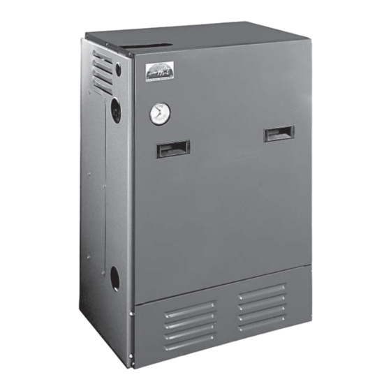
GAS-FIRED, DIRECT VENT,
WARNING Improper installation, adjustment, alteration,
service, or maintenance can cause injury or property
damage. Refer to this manual. For assistance or additional
information consult a qualifi ed installer, service agency, or the
gas supplier.
Sears, Roebuck and Co.,
Hoff man Estates, IL 60179 U.S.A.
K 90-100
CONDENSING,
HOT WATER BOILER
H
P/N# 14683604, Rev. C [12/2010]
Advertisement
Table of Contents

Related Manuals for Kenmore K90-75


Summary of Contents for Kenmore K90-75
- Page 1 INSTALLATION • OPERATION • REPAIR PARTS INSTALLATION • OPERATION • REPAIR PARTS Ownerʼs Manual Model No. K90-50 K90-75 K90-100 CAUTION K 90-100 Read all instructions GAS-FIRED, DIRECT VENT, carefully before starting CONDENSING, the installation. HOT WATER BOILER Save this manual for reference. WARNING Improper installation, adjustment, alteration, service, or maintenance can cause injury or property damage. Refer to this manual. For assistance or additional information consult a qualifi ed installer, service agency, or the These instructions ...
- Page 2 9050100 GASFIRED BOILER Model No. K90-50 K90-75 K90-100 These instructions must be affi xed on or adjacent to the boiler. WARNING Improper installation, adjustment, alteration, service, or maintenance can cause injury or property damage. Refer to this manual. For assistance or additional information consult a qualifi...
-
Page 3: Table Of Contents
TABLE OF CONTENTS Warnings and Safety Symbols ....................... 3 Introduction ..........................4 Boiler Ratings & Capacities ......................5 Boilers For Use At High Altitude ..................... 6 Rules For Safe Installation And Operation ..................8 Before Installing The Boiler ......................8 Placing The Boiler ........................11 Near Boiler Piping ........................12 Combustion Air and Vent Pipe ......................19... -
Page 4: Introduction
INTRODUCTION Th is appliance is a gas-fi red direct vent hot water boiler with cast (sealed combustion) and does not compete with building occupants aluminum boiler sections. A revolutionary cast aluminum heat for fresh air. Sealed combustion (also known as “direct vent”) is the exchanger means better heat transfer and thermal storage than safest and best way to obtain plenty of clean combustion air. -
Page 5: Boiler Ratings & Capacities
BOILER RATINGS & CAPACITIES TABLE #1 – SEA LEVEL RATINGS – NATURAL AND PROPANE GASES Input ++ Heating Capacity Net I=B=R Rating Shipping Model Flue Dia. *(MBH) *(MBH) Weight (lbs.) *(MBH) 90-50 2” CPVC & PVC 90-75 2” CPVC & PVC 90-100 2”... -
Page 6: Boilers For Use At High Altitude
BOILERS FOR USE AT HIGH ALTITUDE Th e boilers (with the exception of the 90-75 LP product) are factory Note that 90-75 LP applications for 5,000 - 10,000 feet above sea equipped for operation at altitudes ranging from 0-10,000 feet above level will require an orifi ce change as well as a gas manifold pres- sea level. - Page 7 BOILERS FOR USE AT HIGH ALTITUDE NOTICE For model 90-75 LP units only at altitudes above 5,000 ft., install 90-75 High Altitude Orifi ce Kit #550001810*. For all other altitudes use factory installed orifi ce. TABLE #2: SERIES 90 PROPANE GAS SERIES 90-50 Stock Factory Btu Value of LP Gas++...
-
Page 8: Rules For Safe Installation And Operation
RULES FOR SAFE INSTALLATION AND OPERATION Read the entire installation manual before beginning the instal- Follow a regular service and maintenance schedule for effi cient lation. Failure to follow these rules for safe installation and and safe operation. operation and these instructions could cause a malfunction Keep boiler area clean of debris and free of combustible and of the boiler and result in death, serious bodily injury, and/or fl ammable materials. - Page 9 BEFORE INSTALLING THE BOILER In the event that the side wall horizontally vented gas Considerations For Boiler Location fueled equipment is installed in a crawl space or an attic, Before selecting a location for the boiler, the following should be the hard wired carbon monoxide detector with alarm and considered.
- Page 10 BEFORE INSTALLING THE BOILER Advise owner of boiler to keep venting and combustion air sphere, and all fl ue products are discharged to outside atmosphere. intake passages free of obstructions. both the venting and com- Combustion air and vent pipe connections must terminate together bustion air intake piping systems connected to the outdoors in the same atmospheric pressure zone, either through the roof must permit fl ow through the piping systems without restric-...
-
Page 11: Placing The Boiler
BEFORE INSTALLING THE BOILER moval of an existing boiler, the following steps shall be followed with Condensate Drain Requirements each appliance remaining connected to the common venting system Condensate drain line to be pitched down to fl oor drain at a mini- placed in operation, while the other appliances remaining connected mum of ¼”... -
Page 12: Near Boiler Piping
NEAR BOILER PIPING When the installation of the boiler is for a new heating system, fi rst NOTICE install all of the radiation units (panels, radiators, baseboard, or tub- The circulator pump and isolation valves are ing) and the supply and return mains. Aft er all heating system piping furnished within a carton inside the boiler and components have been installed, make fi nal connection of the cabinet and can be installed at the installer... - Page 13 NEAR BOILER PIPING Figure 3 - Multi-zone Boiler Piping With Zone Valves...
- Page 14 NEAR BOILER PIPING Figure 4 - Multi-Zone Boiler Piping With Circulators NOTICE When zoning with circulators, the furnished circulator pump should be used as one of the zone pumps. Each stripped end of the electrical wires for the circulator pump inside the junction box should be taped or wire nutted to prevent short circuits.
- Page 15 NEAR BOILER PIPING Figure 5 - Single Zone Boiler Piping Pressure Relief Valve Expansion Tank And Make-Up Water Th e boiler is furnished with a factory installed relief valve in the top Determine required system fi ll pressure, system design temperature, of the boiler.
- Page 16 NEAR BOILER PIPING Figure 6 - Diaphragm Type Expansion Tank Piping...
- Page 17 NEAR BOILER PIPING Figure 7 - Conventional (closed type) Expansion Tank Piping...
- Page 18 NEAR BOILER PIPING Figure 8 - Condensate Drain Piping Condensate Drain Piping Filling Condensate Trap With Water Th e condensate trap is built into the boiler, an external trap is not On Th e Initial Start Up Th e Condensate Trap Must Be Manually required and should NOT be used.
-
Page 19: Combustion Air And Vent Pipe
NEAR BOILER PIPING Th e boiler piping system of a hot water boiler connected to heat- Chilled Water Piping ing coils is located in air handling units where they may be exposed Th e boiler, when used in connection with a refrigeration system, to refrigerated air circulation must be equipped with fl ow control must be installed so the chiller medium is piped in parallel with the valves or other automatic means to prevent gravity circulation of the... - Page 20 COMBUSTION AIR AND VENT PIPE Combustion air and vent piping lengths: COMBUSTION AIR AND VENT PIPING LENGTHS 2” PIPE MINIMUM 2” PIPE MAXIMUM 3” PIPE MINIMUM 3” PIPE MAXIMUM BOILER VENTING VENTING VENTING VENTING SIZE 2 FEET 21 FEET 15 FEET 92 FEET 2 FEET 26 FEET...
- Page 21 COMBUSTION AIR AND VENT PIPE Figure 9 - Roof Vent / Intake terminations • Vent shall not terminate with 6 ft . (1.8m) of a mechanical air-supply inlet to any building. • Vent shall not terminate above a regulator within 3 ft . (900 mm) horizontally of the vertical centerline of the regulator vent outlet to a maximum vertical distance of 15ft (9.5m).
- Page 22 COMBUSTION AIR AND VENT PIPE Figure 10A - Side Wall Vent / Intake terminations - Less Than 12” Clearance Above Grade Less Than 12” Clearance Figure 10B - Side Wall Vent / Intake Terminations - 12” Or More Clearance Above Grade 12” Or More Clearance...
- Page 23 COMBUSTION AIR AND VENT PIPE Figure 11 - Combustion Air and Vent Piping...
-
Page 24: Gas Supply Piping
COMBUSTION AIR AND VENT PIPE Aft er pipes have been cut and pre-assembled, apply cement Installation primer to pipe fi tting socket and end of pipe to insertion mark. Attach combustion air intake piping to supplied Fernco 2” cou- Quickly apply approved cement to end of pipe and fi tting pling on mixer. - Page 25 GAS SUPPLY PIPING Checking The Gas Piping WARNING Th e boiler and its gas connection must be leak tested before placing Never use a match or open fl ame to test for the boiler in operation. Open the manual shutoff valve. Test for leaks leaks.
-
Page 26: Electrical Wiring
ELECTRICAL WIRING grounded ground rod. Connect Circulator Pump Wiring WARNING See Figure 13 (following page) for service switch junction box and Turn off electrical power at fuse box before circulator pump fi eld wiring connections. A 5 feet wiring harness making any line voltage connections. - Page 27 ELECTRICAL WIRING Figure 13 - Field Wiring Connections...
- Page 28 ELECTRICAL WIRING Figure 14 - D - Schematic Wiring Diagram If any of the original wire as supplied with this appliance must be replaced, it must be replaced with type 150°C Thermoplastic wire or its equivalent...
- Page 29 ELECTRICAL WIRING Figure 15 - E - Ladder Wiring Diagram 120 VOLT POWER SUPPLY ON/OFF SWITCH P7-2 P7-1 P7-3 P4-3 P4-1 P10-1 CIRCULATOR MOTOR P5-3 P5-1 P10-2 DRAFT INDUCER HOT SURFACE IGNITER P12-1 P12-2 P6-2 P6-1 P1-3 P1-1 TRANSFORMER P2-1 P2-2 CASTING TEMPERATURE SAFETY SWITCH...
-
Page 30: Controls And Accessories
CONTROLS AND ACCESSORIES Th is section provides a brief description of the key controls and NOTICE accessories found in this boiler. The maximum setpoint of the Aquastat must See the Troubleshooting section (page 47 of the of this installation not exceed 200 °F. manual) for detailed sequences of operation and troubleshooting procedures. - Page 31 CONTROLS AND ACCESSORIES Draft Inducer Blocked Vent Safety Shutoff Th e draft inducer (blower) provides a means for pulling combustion Th is boiler is equipped with a blocked vent safety shutoff means, air into and through the mixer, the burner, the fl ue ways of the which shuts off main burner gas in the event that the fl ow of cast aluminum boiler sections and the fl ue adapter before being combustion products through the fl ueways is reduced.
-
Page 32: Water Treatment & Freeze Protection
WATER TREATMENT & FREEZE PROTECTION When fi lling the boiler water is the preferred heating solution. Most Cleaning the Hydronic System potable water supplies may be used to charge and re-fi ll provided the IMPORTANT: Do not mix diff erent manufacturers’ chlorine and chloride ions levels are less than 100 ppm. - Page 33 WATER TREATMENT & FREEZE PROTECTION If the system has leaked for some reason, the water and antifreeze freezing temperature needed and use the correct amount of anti- chemistry will need to be adjusted. To avoid damage to the boiler, freeze. Never exceed 50% antifreeze by volume. check the pH and chemistry of the boiler solution and consult the •...
-
Page 34: Start Up
START UP Filling Boiler With Water And Purging Air For Systems Placing Boiler In Operation With Diaphragm Type Expansion Tanks WARNING Refer to the appropriate diagrams in Section VII, “Near Boiler Pip- ing, ” for more information. If you do not follow these instructions Close all zone service valves on the supply and return piping. -
Page 35: Operating Instructions
OPERATING INSTRUCTIONS STOP! Read the safety information above on this label. Wait fi ve (5) minutes to clear out any gas. Th en smell for gas, including near the fl oor. If you smell gas, STOP! Follow “B” Set thermostat to lowest setting. in the safety information above on this label. -
Page 36: Check Out Procedure And Adjustment
CHECK OUT PROCEDURE AND ADJUSTMENT Verify Proper Sequence Of Operation Th e sequence can be followed via the diagnostic indicator lamps on the Honeywell S9301A integrated boiler control in Figure #16. Th is is the normal sequence of operation. A more detailed sequence of operation containing potential faults can be found in the service hints section. - Page 37 CHECK OUT PROCEDURE AND ADJUSTMENT SEQUENCE OF OPERATION “DIAGNOSTIC INDICATOR LAMPS” After pre purge, Lamp B goes out and Lamp C illuminates, in- dicating the hot surface igniter is powered for the 20 second igniter warm-up period. The bright yellow orange glow of the hot surface igniter can be observed through the observation port in the front boiler section just above the igniter.
- Page 38 CHECK OUT PROCEDURE AND ADJUSTMENT Set up U-tube manometer or diff erential pressure gauge for Test High Limit Control And Adjust measuring manifold pressure, see Figure #17. While burner is operating, move indicator on high limit control Manometer or gauge must be able to read at least 0.0 to 3.0 below actual boiler water temperature.
- Page 39 CHECK OUT PROCEDURE AND ADJUSTMENT Th e following steps and diagram indicate the location of the Refer to “CHECK OUT PROCEDURE AND ADJUSTMENTS” in connection points required to measure the manifold pressure. this manual when reading the manifold pressure. Th e manifold pressure may be measured using a U-Tube Manometer When measurement is completed, disconnect the U-Tube or a Diff erential Pressure Gauge.
-
Page 40: Installation And Check-Out Certificate
INSTALLATION AND CHECKOUT CERTIFICATE INSTALLATION AND CHECK-OUT CERTIFICATE Boiler Model Serial # Date Installed___________ Measured BTU/HR input____________ Installation instructions have been followed Checkout procedure and adjustments performed Maintenance and Service issues reviewed with owner/ maintenance person Installation booklet affi xed on or adjacent to boiler Installer (Company) Address Phone... -
Page 41: Maintenance And Cleaning
MAINTENANCE AND CLEANING Check that boiler area is free from combustible materials, Maintenance as outlined below can be performed by the owner unless otherwise noted. gasoline, and other fl ammable vapors and liquids. Th e acidic nature of fl ue gasses condensing on the aluminum boiler Circulator pump and blower motor furnished with boiler are permanently lubricated from factory and require no further sections will cause the formation of aluminum oxide. - Page 42 MAINTENANCE AND CLEANING NOTICE The following service procedures must be Monthly During Heating Season performed only by a qualifi ed service agency. 1. Remove jacket front and top panels and check for piping Boiler owner should not attempt these leaks around relief valve and other fi ttings. If found, contact procedures.
- Page 43 MAINTENANCE AND CLEANING Inspection of the fl ue connector requires the following steps (Refer to Reinstall burner and mixer gasket and position mixer the repair parts diagram.) assembly over studs. Install fi ve (5) nuts but do not tighten. Loosen the clamp on the draft inducer end of the 2” Reinstall igniter and igniter gasket and fasten with two fl exible coupling that connects the vent tee to the draft (2) screws.
-
Page 44: Detailed Sequence Of Operation
DETAILED SEQUENCE OF OPERATION Service Hints... - Page 45 DETAILED SEQUENCE OF OPERATION DRAFT INDUCER TEMPERATURE SAFETY SWITCH CASTING TEMPERATURE SAFETY SWITCH IF DRAFT INDUCER TEMPERATURE REACHES IF BURNER OPERATES WHEN BOILER HAS NO TEMPERATURE SAFETY SWITCH SETPOINT, WATER, ALUMINUM BOILER SECTIONS HEAT UP SAFETY SWITCH CONTACTS OPEN IMMEDIATELY RAPIDLY.
- Page 46 DETAILED SEQUENCE OF OPERATION THERMOSTAT ENDS CALL FOR HEAT GAS VALVE AND CIRCULATOR PUMP ARE DE- ENERGIZED AND FLAME LIGHTS GO OUT BLOWER RUNS FOR 30 SECONDS POST PURGE PURGE LIGHT IS “ON” BLOWER IS DE-ENERGIZED FOR 30 SECONDS PURGE LIGHT SHUTS “OFF” BOILER STANDS BY FOR NEXT CALL FOR HEAT...
-
Page 47: Troubleshooting
TROUBLESHOOTING Troubleshooting tools: WARNING Voltmeter to check 120 vac and 24 vac Fire, explosion or shock hazard may cause Continuity tester. property damage, severe injury or death. Inclined manometer or pressure gauge with 0-2.0” Range Do not attempt to modify the physical or (0.01”... - Page 48 TROUBLESHOOTING System Status The indicator lights track the operating sequence. If the system locks out, the lights indicate the point in the sequence of operation where lockout occurs. LIGHT STATUS INDICATES IBC IS ENERGIZED THROUGH 24 VOLT TRANSFORMER. IBC IS NOT ENERGIZED. POWER IBC RECEIVES MORE THAN 40 VAC BLINKING...
- Page 49 TROUBLESHOOTING TROUBLESHOOTING CHART 1 WARNING Electrical shock hazard may cause Serious injury or death. The following procedures may expose you to dangerous line voltage. Use caution to avoid touching live electrical contacts. Service must be performed by a trained, experienced service technician.
- Page 50 TROUBLESHOOTING TROUBLESHOOTING CHART 2...
- Page 51 TROUBLESHOOTING TROUBLESHOOTING CHART 3 CHART 1 OPEN CHECK FOR VAC BLOWER STARTS BETWEEN TERMINALS 1 AND 3 REPLACE IBC AT CONNECTOR CN4 ON IBC CHECK FOR 120 VAC AT REPAIR/REPLCE BLOWER LEADS ON WIRING WIRING FROM IBC HARNESS TO BLOWER REPAIR/REPLACE BLOWER PRESSURE SWITCH...
- Page 52 TROUBLESHOOTING TROUBLESHOOTING CHART 4 CHART 3 CHECK FOR 120 VAC IGNITER/SENSOR WARMS BETWEEN TERMINALS 1 UP AND GLOWS AND 2 AT CONNECTOR YELLOW/ORANGE REPLACE IBC CN1 ON IBC (DURING DURING 20 SECOND IGNITER WARM UP) WARM UP CHECK FOR 120 VAC AT IGNITER/SENSOR LEADS REPAIR/REPLACE WIRING ON WIRING HARNESS...
- Page 53 TROUBLESHOOTING TROUBLESHOOTING CHART 5...
- Page 54 TROUBLESHOOTING TROUBLESHOOTING CHART 6 CHART 5 CHART 5 CHART 5 REPLACE GAS CONTROL. NO #3 NO #2 CHECK GAS ORFICICE SIZE. IS GAS ORIFICE SIZE CORRECT. CHECK REPAIR PARTS LIST FOR CORRECT SIZE. IS GAS ORIFICE CLEAR OF BLOCKAGE. RUNS FOR 25-50 SECONDS, THEN TURNS OFF.
-
Page 55: Differential Air Pressure Switch Check
DIFFERENTIAL AIR PRESSURE SWITCH CHECK What Is System Status? PRESSURE Th e following steps and diagram indicate the locations of the con- BOILER DIFFERENTIAL SWITCH nection points required to check the diff erential air pressure. STATUS PRESSURE (W.C.) CONNECTS Th e diff erential air pressure switch is a safety device which will Not Running 0”... - Page 56 REPAIR PARTS Jacket and Base Assembly TYP OF 4...
- Page 57 REPAIR PARTS JACKET AND BASE ASSEMBLY ITEM KEY # DESCRIPTION QUANTITY NUMBER FRONT PANEL 750001020 RIGHT PANEL 750001021 LEFT PANEL 750001022 BACK PANEL 750001023 TOP PANEL 750001024 BASE 750001025 CONTROL PANEL 650001026 AT140B1016 TRANSFORMER 24 VAC 550001339 - - - - - - - - - - - - UT 1013-10 INTEGRATED BOILER CONTROL...
- Page 58 REPAIR PARTS Condensate Drain Trap Assembly Connect to the drain port at the bottom of boiler Connect to the drain port at the exhauster KEY # DESCRIPTION QUANTITY ITEM NUMBER 59019 ½”IDx1/8” THK VINYL TUBING AS REQUIRED 14631035 57134 ¾” SNAP GRIP CLAMP 14631141 62067 ½”ID HOSE TEE 14631320...
- Page 59 REPAIR PARTS Flue Adapter and Exhaust Assembly KEY # DESCRIPTION QUANTITY ITEM NUMBER EXHAUST TEE ASSEMBLY [INCLUDES- 1-A,B,C,D,E & F] 43800001 62017 1/2”NPTx1/2”ID TUBE STRAIGHT HOSE ADAPTER 14631101 PVC 1 1/2” MALE SLIP x 1/2” FEMALE NPT BUSHING 14631013 PVC SCH 40 2”x1-1/2” REDUCER S636 BUSHING 240006817 ½X1⅞’’X.90 ALUMINUM FLAT WASHER 1 14695815...
- Page 60 REPAIR PARTS Boiler Block and Piping Assembly...
- Page 61 REPAIR PARTS BOILER BLOCK AND PIPING ASSEMBLY KEY # ITEM NUMBER DESCRIPTION QUAN- TITY 41800950 KIT BLOCK REPL Q90-100 (INCLUDES #2 THRU #19) 14607044 NPL,1-1/4X2-1/2,BI,STD 14607201 NPL,3/4X2,BI,STD 14619002 OBSERVATION GLASS, 3/4” 14631000 SWITCH CASTING TEMP Q90 36T26-42930 300 14631004 ADAPTER, SIGHT GLASS 14631005 FITTING, 125HBL-4-2 1/8”X1/4”BR.B+ 14631101...
- Page 62 REPAIR PARTS Mixer and Air Pressure Switch Assembly...
- Page 63 REPAIR PARTS MIXER AND AIR PRESSURE SWITCH ASSEMBLY KEY # DESCRIPTION QUANTITY ITEM NUMBER BURNER GASKET 14631023 BURNER KIT, 50 &100 NAT/LP, 0’-10,000’ (Contains: 1, 2, 3, 7, 10, 11, 12 ) 550001811 BURNER KIT, 75 NAT, 0’-10,000’ (Contains: 1, 2, 3, 7, 10, 11, 12 & 29) 550001811 BURNER KIT, 75 LP, 0’- 5,000’...
- Page 64 Model No. CONDENSING, K90-50 HOT WATER BOILER K90-75 K90-100 Now that you have purchased your boiler, should a need ever exist for repair parts or service, simply contact any Sears Service Center. Be sure to provide all pertinent facts when you call or visit.
Need help?
Do you have a question about the K90-75 and is the answer not in the manual?
Questions and answers