Table of Contents
Advertisement
Quick Links
Owner's Manual
Model No.
3EW.65
3EW.75
3EW1.00
4EW.90
4EW1.25
4EW1.50
5EW1.20
5EW1.75
5EW2.00
CAUTION
Read all instructions
carefully before starting
the installation.
Save this manual
for reference.
These instructions
must be affixed on or
adjacent to the boiler.
InstallatIon • operatIon • repaIr parts
H
These boilers are low pressure, sectional cast iron boilers constructed
and hydrostatically tested for a maximum working pressure of psi in
accordance with A.S.M.E. (American society of Mechanical Engineers)
Section IV Standards for cast iron heating boilers. They are capacity
rated in accordance with the code of the I=B=R (Hydronics Institute).
Sears, Roebuck and Co.,
Hoffman Estates, IL 60179 U.S.A.
eW
oIl FIred
BoIler
OIL FIRED BOILERS
P/N# 14683606, Rev. 1.2 [08/06]
Advertisement
Table of Contents

Related Manuals for Kenmore 3EW.75


Summary of Contents for Kenmore 3EW.75
- Page 1 InstallatIon • operatIon • repaIr parts Owner’s Manual Model No. 3EW.65 3EW.75 3EW1.00 4EW.90 4EW1.25 4EW1.50 5EW1.20 5EW1.75 5EW2.00 CAUTION oIl FIred Read all instructions BoIler carefully before starting the installation. Save this manual for reference. OIL FIRED BOILERS These boilers are low pressure, sectional cast iron boilers constructed and hydrostatically tested for a maximum working pressure of psi in accordance with A.S.M.E.
-
Page 3: Warranty
Warranty SEarS KENMORE CAST IRON BOILERS FULL ONE YEAR WARRANTY ON HOT WATER AND GAS STEAM CAST IRON BOILERS For one (1) year from the date of installation, when this boiler is installed and maintained in accordance with our instructions. Sears will repair defects in material or workmanship in the boiler, free of charge. -
Page 4: Boiler Ratings And Capacities
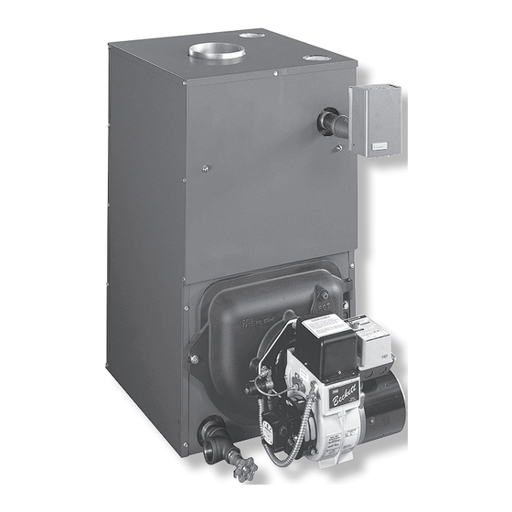
IntrODUCtIOn The Empire Water boiler is a natural draft oil fired boilers include a swing door, Honeywell aquastat, hot water boiler comprised of cast iron sections. temperature and pressure gage, relief valve, drain The Empire Water boiler is available with 3, 4, valve, 2 Delevan oil nozzles for multiple firing rates or 5 cast iron sections. - Page 5 BOIlEr ratIngS anD CaPaCItIES These low pressure oil fired hot water boilers equal to the calculated peak heating load (heat are constructed and hydrostatically tested for a loss) for the building or area(s) served by the maximum working pressure of 50 psig (pounds boiler and associated hot water heating systems.
- Page 6 rUlES FOr SaFE InStallatIOn anD OPEratIOn 1. Read the Owner’s Manual for Safe Operation valve will automatically lift open. Lifting of the carefully. Failure to follow the rules for relief valve can discharge large quantities safe operation and the instructions can of steam and hot water, which may damage cause a malfunction of the boiler and result in the surroundings.
-
Page 7: Before You Start
BEFOrE yOU Start lOCatIng tHE BOIlEr Complete all of the following prior to installing the 1. Place the boiler in a location centralized with the piping boiler. system and as close to the chimney as possible. A. Check to be sure you have selected the right size 2. -
Page 8: Installation Requirements
InStallatIOn rEQUIrEMEntS ALWAYS KEEP THE MANUAL FUEL SUPPLY VALVE SHUT OFF, IF THE BURNER IS SHUT DOWN FOR AN EXTENDED PERIOD OF TIME. -
Page 9: Fresh Air For Combustion
FrESH aIr FOr COMBUStIOn WarnIng EXAMPLE 2: Boiler Located in Confined Space All Air from Inside the Building: The confined Be sure to provide enough fresh air for combustion. space shall be provided with two permanent Enough air ensures proper combustion and openings communicating directly with an additional assures that no hazard will develop due to the room(s) of sufficient volume so that the combined... - Page 10 FrESH aIr FOr COMBUStIOn B. All Air from Outdoors: The confined space square inch per 4,000 Btu per hour of shall be provided with two permanent total input rating of all equipment in the openings, one commencing within 12 inches enclosure.
-
Page 11: System Piping
SyStEM PIPIng 1. When the installation of the boiler is for a new Low Design Water Temperature Systems (Be- heating system, first install all of the radiation units low 140° F) And Large Water Content Systems (panels, radiators, baseboard, or tubing) and the WarnIng supply and return mains. - Page 12 SyStEM PIPIng arrangEMEnt ZOnIng WItH ZOnE ValVES > CIRCULATOR ON SUPPLY PIPING PUMPS AWAY FROM EXPANSION TANK > PIPING ARRANGED FOR “POWER PURGING” AIR OUT OF SYSTEM PIPING, REFER TO THIS MANUAL’S SECTION ON “FILLING THE SYSTEM WITH WATER” OPTION #1...
- Page 13 SyStEM PIPIng arrangEMEnt ZOnIng WItH CIrCUlatOrS > CIRCULATOR ON SUPPLY PIPING PUMPS AWAY FROM EXPANSION TANK > PIPING ARRANGED FOR “POWER PURGING” AIR OUT OF SYSTEM PIPING, REFER TO THIS MANUAL’S SECTION ON “FILLING THE SYSTEM WITH WATER” OPTION #1...
- Page 14 SyStEM PIPIng arrangEMEnt altErnatE nEar BOIlEr PIPIng > DIAPHRAGM EXPANSION TANK MOUNTED OFF > PER THIS MANUAL, USE OPTION #2 IN “FILL- THE BOILER ING THE SYSTEM WITH WATER” > CIRCULATOR ON SUPPLY PIPING PUMPS AWAY > THIS PIPING ARRANGEMENT CAN BE USED FROM EXPANSION TANK WITH ZONE vALvES OR ZONE CIRCULATORS...
- Page 15 SyStEM PIPIng arrangEMEnt altErnatE nEar BOIlEr PIPIng Boilers may be factory packaged with a respond more quickly to a call for domestic hot tankless heater coil see figure below. This water. A tempering valve (mixing valve) is also coil provides instantaneous heating of water recommended as shown in figure below.
- Page 16 SyStEM PIPIng arrangEMEnt altErnatE nEar BOIlEr PIPIng 8. Antifreeze added to boilers must be nontox- boiler may reduce capacity by 10% or more ic, and must be of a type specifically intended and increase fuel consumption. Tankless for use in closed hydronic heating systems. coil performance will fall as concentration of Under no circumstances should automotive antifreeze is increased.
-
Page 17: Chimney And Chimney Connections
CHIMnEy anD CHIMnEy COnnECtIOnS For oilfired boilers for connections to vents or chimneys, vent installations shall be in accordance with applicable provisions of INSTALLATION OF OIL BURNING EQUIPMENT, NFPA31 latest revision, and applicable provisions of local building codes. This is a very important part of your heating sys- It is cheaper to rebuild a poor chimney than to pay tem. -
Page 18: Typical Chimney Connection
tyPICal CHIMnEy COnnECtIOn MINIMUM HEIGHT: MUST BE AT LEAST 3 FT HIGHER THAN HIGHEST PART OF PASSAGE THROUGH ROOF. MUST BE AT LEAST 2 FT HIGHER THAN ANY NEIGHBORING OBJECT WITHIN 10 FT. MUST HAVE AN UNOBSTRUCTED TOP OPENING. -
Page 19: Electrical Connections
ElECtrICal COnnECtIOnS THERMOSTAT ELECTRIC POWER SUPPLY Install a 24volt thermostat (not provided) in a proper All electrical work must conform to your local codes location. The location of the thermostat has an important as well as the National Electrical Code. If you are not effect on boiler system operation. -
Page 20: Equipment And Optional Accessories
EQUIPMEnt anD OPtIOnal aCCESSOrIES RELIEF vALvE (provided) DIAPHRAGM EXPANSION TANK (not provided) Each low pressure hot water heating boiler is The diaphragm type expansion tank takes provided with a relief valve for over pressure the place of the conventional expansion tank. protection of the boiler and heating system. - Page 21 EQUIPMEnt anD OPtIOnal aCCESSOrIES MAIN AIR VENT: for down flow systems or dia- DRAIN vALvE (provided) phragm type expansion tanks (not provided) The drain valve is a manually operated valve that Before a system is filled with water, there is air in provides a means of draining all the water from the the pipes and radiation units.
-
Page 22: Filling The Boiler
FIllIng tHE BOIlEr HOW A HOT WATER SYSTEM OPERATES d) Once all zones are filled with water and purged The entire heating system (boiler, piping, and of air, close the power purging drain valve and radiation units) is filled with water. As the water in fill line shut off valve, open the main shutoff the boiler is heated, it is circulated from the top of valve, and adjust the throttling valves and... -
Page 23: Operating The Boiler
OPEratIng tHE BOIlEr DO NOT TAMPER WITH THE UNIT OR CONTROLS IMPORTANT You or your installer must follow these instructions carefully. STARTING: Fill the entire system with water. Vent AIR SUPPLY FOR COMBUSTION: Do not install all air from the system following the section for the boiler in rooms with insufficient air, unless FILLING THE BOILER. - Page 24 OPEratIng tHE BOIlEr burner should be started and stopped several NOZZLES AND ELECTRODES: Use the proper times to assure good operation with no fluttering size, spray angle, and spray pattern nozzle. Refer or rumbling. Verify that there are no oil leaks and to the recommended nozzle selection charts at then record the nozzle size, oil pressure, combus- the end of this manual.
- Page 25 OPEratIng tHE BOIlEr...
-
Page 26: Checking And Adjusting Controls
CHECKIng anD aDJUStIng COntrOlS A boiler using a tankless coil is configured with a Honeywell L8124C Combination Hi/Low Limit Aqua- stat Relay (refer back to the SYSTEM PIPING section for more details). A boiler not using a tankless coil is configured with a Honeywell L8148A Hi Limit Aquastat Relay. Instructions for the control provided are included with the boiler. -
Page 27: Maintenance
MaIntEnanCE CONvENTIONAL EXPANSION TANK: As ANNUALLY: To assure trouble free operation, it noted in the EQUIPMENT AND OPTIONAL is recommended that the flue passages, combus- ACCESSORIES section, this tank may become tion chamber area (target wall, fire door insula- water logged or may receive an excess of air. tion, durablanket), burner adjustment, operation Frequent automatic opening of the relief valve of the controls, and boiler seals (fire door gasket... -
Page 28: Oil Boiler / Burner Cleaning Instructions
OIl BOIlEr / BUrnEr ClEanIng InStrUCtIOnS OIL BOILER CLEANING: to the combustion chamber first double check 1. Shut off all electrical power to the boiler / burner that the shut off valve on the fuel oil line is and shut off fuel oil supply. closed and then disconnect the fuel oil line. -
Page 29: Oil Burner Cleaning
OIl BUrnEr ClEanIng These are general instructions for cleaning an oil burner. For specifics, con- sult the burner manufacturer’s instructions. 6. Inspect and clean the oil burner blower 1. Make sure all electrical power to the boiler / wheel. burner and the fuel supply to the burner are shut off. -
Page 30: Service Hints
SErVICE HIntS You may avoid inconvenience and service calls by checking these points before you call for service: FOR YOUR SAFETY WHAT TO DO IF YOU SMELL GAS 1. Do Not try to light any appliance. 2. Do not touch any electric switch, do not use the phone. 3. -
Page 31: Electrical Wiring
ElECtrICal WIrIng BOILER WITHOUT TANKLESS COIL AND AND BOILER WITH TANKLESS COIL AND AND HONEYWELL L8148A AQUASTAT CONTROL HONEYWELL L8124C AQUASTAT CONTROL (BECKETT AFG BURNER SHOWN) (BECKETT AFG BURNER SHOWN) Service Company: Serviceman: Address: Telephone:... -
Page 32: Sequence Of Operations
SEQUEnCE OF OPEratIOnS BOILER WITH TANKLESS COIL: heating. The sequence of operation for the burner and circulator is as follows: Aquastat high limit controller: 1. Thermostat calls for heat, completing circuit be- The aquastat control’s high limit contacts open and tween terminals T &... - Page 33 SEQUEnCE OF OPEratIOnS BOILER LESS TANKLESS COIL: Aguastat high limit controller: The aquastat control’s high limit contacts open and turn off the burner when the boiler water temperature reaches the control’s high limit set point. The high limit contacts automatically reset after the boiler water temperature drops past the set point by 10°F, which is a fixed differential.
-
Page 34: Repair Parts
rEPaIr PartS ITEM DESCRIPTION Water Boiler Back Section (EW3) 40300008 40300008 40300008 Water Boiler Middle Section (EW2) 40300007 40300007 40300007 Empire Water Front Section (EW1) 40300006 40300006 40300006 Cast Iron Machined Nipples 2” 43300976 43300976 43300976 1/4” Tie Rods 14605002 14605051 14605053 Tie Rods 1/4”20 Hex Head Nut... - Page 35 rEPaIr PartS ITEM DESCRIPTION PART# Empire Water Front Section (EW1) 40300006 3/8” - 16 X 2-1/4” stud 14695125 3/8” Whizlock Nut 14695126 Swing Door Insulation 14614014 Swing Door Hinge 40300010 1/4” x 2” Round Head Rivet 14695121 3/8” x 1” Hex Head Serrated Flange Bolt 14695124 3/8”...
- Page 36 rEPaIr PartS ITEM DESCRIPTION Right Side Jacket Panel 42500244 42500245 42500246 Back jacket Panel 42500269 42500269 42500269 Top jacket Panel 42500254 42500255 42500256 Left Side Jacket Panel 42500264 42500265 42500266 Upper Side Jacket Panel 42500267 42500267 42500267 5/16” Acorn Nut 14695042 14695042 14695042...
- Page 37 rEPaIr PartS ITEM DESCRIPTION Beckett AFG FHead Oil Burner 1050036 1050037 - - - - Beckett AFG Variable Head Oil Burner - - - - - - - - 1050038 – Beckett AFG FHead Low Fire Kit (0.65 gph) 43300015 - - - - - - - - –...
-
Page 38: Beckett Oil Burner, Nozzle, And Air Setting
PLATE BURNER BAFFLE BAND (gph) 3EW.65* 0.50-80º B 0.65 F0 - 1 ⅛ 10/0 3 ⅝ AFG F-HEAD 3EW.75 0.65-70º B 0.75 F3 - 1 ⅛ 10/0 3 ½ AFG F-HEAD 3EW-1.00 0.85-70º B 1.00 F3 - 1 ⅛ 10/2 3 ½... - Page 40 Owner’s Manual Model No. oIl FIred BoIler 3EW.65 3EW.75 Now that you have purchased your Boiler, 3EW1.00 should a need ever exist for repair parts or ser- 4EW.90 vice, simply contact any Sears service Center. 4EW1.25 Be sure to provide all pertinent facts when you call or visit.
Need help?
Do you have a question about the 3EW.75 and is the answer not in the manual?
Questions and answers