Siemens SITRANS LR110 Operating Instructions Manual
Radar transmitters
Hide thumbs
Also See for SITRANS LR110:
- Operating instructions manual (66 pages) ,
- Operating instructions manual (60 pages) ,
- Operating instructions manual (58 pages)

Related Manuals for Siemens SITRANS LR110


Summary of Contents for Siemens SITRANS LR110
- Page 1 Edition 10/2023 Operating Instructions SITRANS L Radar transmitters LR110, Modbus https://www.siemens.com/processautomation...
- Page 2 Preface Introduction Safety notes SITRANS L Description Radar transmitters LR110, Modbus Installing/mounting Connecting Operating Instructions Access protection Setup with smart device (Bluetooth) Operating Diagnostics and troubleshooting Service and maintenance Certificates and approvals Technical data and dimensions 10/2023 A5E49829013...
- Page 3 Note the following: WARNING Siemens products may only be used for the applications described in the catalog and in the relevant technical documentation. If products and components from other manufacturers are used, these must be recommended or approved by Siemens. Proper transport, storage, installation, assembly, commissioning, operation and maintenance are required to ensure that the products operate safely and without any problems.
-
Page 4: Table Of Contents
Table of contents Preface ............................v Introduction ........................... 1 Function ........................ 1 Target group ......................1 Symbols used ......................1 Safety notes .......................... 3 Authorised personnel .................... 3 Appropriate use ....................3 Warning about incorrect use ................. 3 General safety instructions ..................3 Radar frequencies for worldwide use .............. - Page 5 Table of contents Connecting ......................23 Operating ..........................25 Diagnostics and troubleshooting ..................31 Maintenance ....................... 31 Rectify faults ....................... 31 Status messages according to NE 107 ..............32 Treatment of measurement errors ............... 34 Return procedure ....................39 Technical support ....................40 How to proceed if a repair is necessary ...............
-
Page 6: Preface
Preface Safety instructions for Ex areas: WARNING Take note of the Ex specific safety instructions for Ex applications. These instructions are attached as documents to each transmitter with Ex approval and are part of the operating instructions. Editing status: 2023-10-26 LR110, Modbus Operating Instructions, 10/2023, A5E49829013... - Page 7 Preface LR110, Modbus Operating Instructions, 10/2023, A5E49829013...
-
Page 8: Introduction
Introduction Function This instruction provides all the information you need for mounting, connection and setup as well as important instructions for maintenance, fault rectification, safety and the exchange of parts. Please read this information before putting the transmitter into operation and keep this manual accessible in the immediate vicinity of the device. - Page 9 Introduction 1.3 Symbols used Ex applications This symbol indicates special instructions for Ex applications. • List The dot set in front indicates a list with no implied sequence. Sequence of actions Numbers set in front indicate successive steps in a procedure. Disposal This symbol indicates special instructions for disposal.
-
Page 10: Safety Notes
During work on and with the device, the required personal protective equipment must always be worn. Appropriate use SITRANS LR110 is a transmitter for continuous level measurement. You can find detailed information about the area of application in chapter ""Product description". -
Page 11: Radar Frequencies For Worldwide Use
A Class 2 power supply unit has to be used for the installation in the USA and Canada. Security information Siemens provides products and solutions with industrial security functions that support the secure operation of plants, systems, machines and networks. To protect plants, systems, machines and networks against cyber threats, it is necessary to implement (and continuously maintain) a holistic, state-of-the-art industrial security concept. - Page 12 Use of product versions that are no longer supported, and failure to apply the latest updates may increase customer’s exposure to cyber threats. To stay informed about product updates, subscribe to the Siemens Industrial Security RSS Feed under: https://www.siemens.com/industrialsecurity...
- Page 13 Safety notes 2.7 Security information LR110, Modbus Operating Instructions, 10/2023, A5E49829013...
-
Page 14: Description
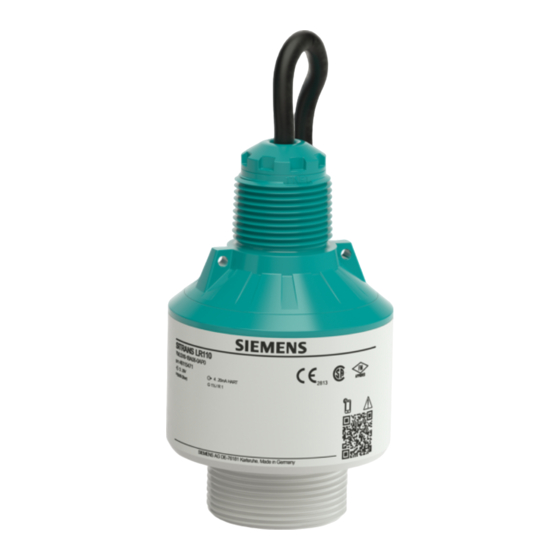
Description Configuration Scope of delivery The scope of delivery encompasses: • SITRANS LR110 radar transmitter • Information sheet ""Documents and software" with: • Transmitter serial number • QR code with link for direct scanning • Information sheet ""Device Bluetooth and Parameter Access Codes" with: •... -
Page 15: Principle Of Operation
Manufacturer information Principle of operation Application area SITRANS LR110 is a radar transmitter for non-contact, continuous level measurement. It is suitable for liquids and solids in practically all industries. Functional principle The transmitter emits a continuous, frequency-modulated radar signal through its antenna. -
Page 16: Packaging, Transport And Storage
Description 3.4 Packaging, transport and storage Transmitter Smart device Figure 3.2 Wireless connection to standard operating devices with integrated Bluetooth LE Packaging, transport and storage Packaging Your transmitter was protected by packaging during transport. Its capacity to handle normal loads during transport is assured by a test based on ISO 4180. The packaging consists of environment-friendly, recyclable cardboard. -
Page 17: Accessories
Description 3.5 Accessories • Dry and dust free • Not exposed to corrosive media • Protected against solar radiation • Avoiding mechanical shock and vibration Storage and transport temperature • Storage and transport temperature see chapter ""Supplement - Technical data - Ambient conditions"... -
Page 18: Installing/Mounting
Installing/mounting General instructions Ambient conditions The transmitter is suitable for standard and extended ambient conditions acc. to DIN/ EN/BS EN/IEC/ANSI/ISA/UL/CSA 61010-1. It can be used indoors as well as outdoors. Process conditions Note For safety reasons, the transmitter must only be operated within the permissible process conditions. -
Page 19: Mounting Instructions
Installing/mounting 4.3 Mounting instructions Figure 4.1 Mounting via a mounting bracket Mounting instructions Installation position When mounting the device, keep a distance of at least 200 mm (7.874 in) from the vessel wall. If the device is installed in the center of dished or round vessel tops, multiple echoes can arise. - Page 20 Figure 4.5 Recommended threaded nozzle mounting of SITRANS LR110 If the reflective properties of the medium are good, you can mount SITRANS LR110 on nozzles longer than the antenna. The nozzle end should be smooth and burr-free, if possible also rounded.
- Page 21 Installing/mounting 4.3 Mounting instructions Figure 4.6 Nozzle mounting with deviating nozzle dimensions Nozzle diameter d Nozzle length h 40 mm 1½" ≤ 150 mm ≤ 5.9 in 50 mm 2" ≤ 200 mm ≤ 7.9 in 80 mm 3" ≤ 300 mm ≤ 11.8 in 100 mm 4" ≤ 400 mm ≤ 15.8 in 150 mm 6" ≤ 600 mm ≤ 23.6 in Alignment - Liquids In liquids, direct the device as perpendicular as possible to the medium surface to achieve optimum measurement results.
-
Page 22: Measurement Setup - Flow
Installing/mounting 4.4 Measurement setup - Flow Figure 4.8 Agitators Foam generation Through the action of filling, stirring and other processes in the vessel, foams which considerably damp the emitted signals may form on the medium surface. If foams lead to measurement errors, you should use transmitters with guided radar. Measurement setup - Flow Mounting In general, the following must be observed while mounting the device:... - Page 23 Installing/mounting 4.4 Measurement setup - Flow • Venturi, trapezoidal weir, rectangular flume (Q = k x h • V-Notch, triangular overfall (Q = k x h Channel with dimensions according to ISO standard: When selecting these curves, the dimensions of the flume must be known and entered via the assistant.
- Page 24 Installing/mounting 4.4 Measurement setup - Flow Rectangular overfall Overfall orifice (side view) Upstream water Tailwater Overfall orifice (view from tailwater) Figure 4.9 Flow measurement with rectangular flume: h = max. filling of the rectangular max. flume Khafagi-Venturi flume Position transmitter Venturi flume Figure 4.10 Flow measurement with Khafagi-Venturi flume: h = max.
- Page 25 Installing/mounting 4.4 Measurement setup - Flow LR110, Modbus Operating Instructions, 10/2023, A5E49829013...
-
Page 26: Connecting
Connecting Preparing the connection Safety instructions Always keep in mind the following safety instructions: • Carry out electrical connection by trained, qualified personnel authorised by the plant operator WARNING Only connect or disconnect in de-energized state. Voltage supply The data for power supply are specified in chapter ""Technical data". Note Power the transmitter via an energy-limited circuit (power max. -
Page 27: Wiring Plan
Connecting 5.2 Wiring plan Wiring plan Wire assignment, connection cable Figure 5.1 Wire assignment in permanently connected connection cable Wire colour Function Polarity Brown Voltage supply Plus (+) Blue Voltage supply Minus (-) Black Modbus signal D+ Plus (+) White Modbus signal D- Minus (-) Shielding LR110, Modbus... -
Page 28: Access Protection
Access protection Bluetooth radio interface Devices with a Bluetooth radio interface are protected against unwanted access from outside. This means that only authorized persons can receive measured and status values and change device settings via this interface. Bluetooth PIN A Bluetooth PIN is required to establish Bluetooth communication via the adjustment tool (smartphone/tablet/notebook). - Page 29 Access protection 6.2 Protection of the parameterization Device Access PUK The Device Access PUK allows unlocking the device in case the user PIN is no longer known. It can't be changed. The Device Access PUK can also be found on the supplied information sheet ""Device Bluetooth and Parameter Access Codes".
-
Page 30: Setup With Smart Device (Bluetooth)
Setup with smart device (Bluetooth) Connecting Connecting Start the adjustment app. The smart device searches automatically for Bluetooth- capable transmitters in the area. The devices found are listed. Select the requested transmitter in the device list. Authenticate When establishing the connection for the first time, the operating tool and the transmitter must authenticate each other. - Page 31 Setup with smart device (Bluetooth) 7.1 Connecting LR110, Modbus Operating Instructions, 10/2023, A5E49829013...
-
Page 32: Operating
Operating To configure the device: Download and install the SITRANS mobile IQ app from the App store to your mobile device. Launch the app. Devices in range will appear. Click on the device you wish to connect to. On first connection, a PIN code shipped with the device needs to be entered (see Device Bluetooth and Parameter Access Codes sheet). - Page 33 Operating Use the Setup/Quick Commissioning to configure the transmitter for your application type. LR110, Modbus Operating Instructions, 10/2023, A5E49829013...
- Page 34 Operating LR110, Modbus Operating Instructions, 10/2023, A5E49829013...
- Page 35 Operating LR110, Modbus Operating Instructions, 10/2023, A5E49829013...
- Page 36 Operating • Mode 1: EU, Albania, Andorra, Azerbaijan, Australia, Belarus, Bosnia and Herzegovina, Canada, Liechtenstein, Morocco, Moldavia, Monaco, Montenegro, New Zealand, Northern Macedonia, Norway, San Marino, Saudi Arabia, Serbia, South Africa, Switzerland, Turkey, Ukraine, United Kingdom, USA • Mode 2: Brazil, Japan, South Korea, Taiwan, Thailand •...
- Page 37 Operating LR110, Modbus Operating Instructions, 10/2023, A5E49829013...
-
Page 38: Diagnostics And Troubleshooting
Diagnostics and troubleshooting Maintenance Maintenance If the device is used properly, no special maintenance is required in normal operation. Precaution measures against buildup In some applications, buildup on the antenna system can influence the measuring result. Depending on the transmitter and application, take measures to avoid heavy soiling of the antenna system. -
Page 39: Status Messages According To Ne 107
Diagnostics and troubleshooting 9.3 Status messages according to NE 107 • Signal processing Fault rectification The first measures are: • Evaluation of fault messages • Checking the output signal • Treatment of measurement errors A smart device (smartphone/tablet) with the adjustment app or a PC/notebook with the PDM and the suitable EDD offer you further comprehensive diagnostic possibilities. - Page 40 Diagnostics and troubleshooting 9.3 Status messages according to NE 107 Code Cause Rectification Text message F105 The transmitter is still in the switch-on Wait for the end of the switch-on phase, the measured value could not phase Determine measured yet be determined value Duration up to 3 minutes depending on the measurement environment...
-
Page 41: Treatment Of Measurement Errors
Diagnostics and troubleshooting 9.4 Treatment of measurement errors Code Cause Rectification Text message Error in the delivery Load XML file with transmitter data status into the transmitter M501 Hardware error EEPROM Send transmitter for repair Error in the delivery status M507 Error during setup Carry out reset and repeat setup Error in the... - Page 42 Diagnostics and troubleshooting 9.4 Treatment of measurement errors If the level is too low, the reason could be a line resistance that is too high Fault description Cause Rectification Measured value shows a Min./max. adjustment not correct Adapt min./max. adjustment too low or too high level Incorrect linearization curve Adapt linearization curve Measured value jumps...
- Page 43 Diagnostics and troubleshooting 9.4 Treatment of measurement errors Fault description Cause Rectification Measured value jumps Due to strong turbulence and Carry out a auto false echo towards 100 % during foam generation during filling, the suppression filling amplitude of the level echo sinks. Measured value jumps to false signal Measured value jumps...
- Page 44 Diagnostics and troubleshooting 9.4 Treatment of measurement errors Fault description Cause Rectification echo suppression in the close range by editing Fault description Cause Rectification Measured value shows a Min./max. adjustment not correct Adapt min./max. adjustment too low or too high level Incorrect linearization curve Adapt linearization curve Measured value jumps...
- Page 45 Diagnostics and troubleshooting 9.4 Treatment of measurement errors Fault description Cause Rectification Reflections from the medium Select a more suitable installation surface via the vessel wall position, optimize transmitter (deflection) orientation, e.g. with a swivelling holder Measured value jumps Changing condensation or Carry out a auto false echo sporadically to 100 % contamination on the antenna...
-
Page 46: Return Procedure
Required forms: • Delivery note • Return goods delivery note with the following information: https:// www.siemens.com/processtransmitteration/returngoodsnote • Product (item description) • Number of returned devices/replacements parts • Reason for returning the item(s) •... -
Page 47: Technical Support
[https://www.siemens.com/ processtransmitteration/certificates] or on an included DVD. How to proceed if a repair is necessary If it is necessary to repair the transmitter, please contact Siemens. You find the locations on www.siemens.com/processautomation [https://www.siemens.com/ processautomation]. LR110, Modbus Operating Instructions, 10/2023, A5E49829013... -
Page 48: Service And Maintenance
If you have no way to dispose of the old transmitter properly, please contact us concerning return and disposal. Further information about devices containing batteries can be found at: (https:// support.industry.siemens.com/cs/document/109479891/) Note Special disposal required The device includes components that require special disposal. - Page 49 Service and maintenance 10.2 Disposal LR110, Modbus Operating Instructions, 10/2023, A5E49829013...
-
Page 50: Certificates And Approvals
The Bluetooth radio module in the device has been tested and approved according to the current edition of the applicable country-specific norms or standards. The confirmations as well as regulations for use can be found in the document ""Radio licenses" supplied or on www.siemens.com/level [https://www.siemens.com/ level]. 11.2 Approvals for Ex areas Approved versions for use in hazardous areas are available or in preparation for the device series. -
Page 51: Conformity
The device complies with the legal requirements of the applicable country-specific directives or technical regulations. We confirm conformity with the corresponding labelling. You can find the corresponding conformity declarations on www.siemens.com/level [https://www.siemens.com/level]. 11.6 NAMUR recommendations NAMUR is the automation technology user association in the process industry in Germany. -
Page 52: Technical Data And Dimensions
Technical data Note for approved transmitters Device specifications: Siemens makes every effort to ensure the accuracy of these specifications, but reserves the right to change them at any time. Device-specific approvals: The device-specific approvals are always to be found on the nameplates on the device. - Page 53 Technical data and dimensions 12.1 Technical data Minimum measuring distance • Mode 1, 2, 4 0 mm (0 in) • Mode 3 ≥ 250 mm (9.843 in) Depending on application and medium Depending on the operating conditions Reference point Measured variable, max. measuring range Figure 12.1 Data of the input variable Output variable Output •...
- Page 54 Technical data and dimensions 12.1 Technical data Deviation with bulk solids The values depend to a great extent on the application. Binding specifications are thus not possible. Already included in the meas. deviation Variables influencing measurement accuracy Temperature drift - Digital output < 3 mm/10 K, max. 5 mm Additional deviation through electromagnetic < 50 mm...
-
Page 55: Modbus - Overview
Technical data and dimensions 12.2 Modbus - Overview Frequency 2.402 … 2.480 GHz Max. emitted power +2.2 dBm Max. number of participants Effective range typically 25 m (82 ft)Depending on the local conditions Adjustment Smart device SITRANS mobile IQ Voltage supply Operating voltage 8 … 30 V DC Power consumption without/with bus communication typ. at •... -
Page 56: Communication (Holding Register)
Technical data and dimensions 12.3 Communication (Holding Register) • Modbus RTU (data transmission is binary signs) The data exchange between field device and host is done via registers. The input registers only allow read access, holding registers both read and write access. The device supports the above mentioned points. -
Page 57: Measured Values (Input Register)
Technical data and dimensions 12.5 Measured values (Input Register) Register Register Name Data type Configurable Values Unit Default Number Value 3601 Application liquid enum16 0 =Storage, 1= Process, Storage 13=Wetwell, 8=Plastic, 9=Open, 12=Demo 3602 Application solid enum16 0=Silo, 4= Bin/Hopper, Silo 3=Open,12=Demo 12.5 Measured values (Input Register) - Page 58 Technical data and dimensions 12.5 Measured values (Input Register) Register Register Name Data Note Number type Access 1400 Status enum8 See Register 100 1402 float32 Primary Variable in Byte Order CDAB 1414 float32 Secondary Variable in Byte Order CDAB 1426 float32 Third Variable in Byte Order CDAB 1438 float32...
-
Page 59: Additional Measurement Data (Input Register)
Technical data and dimensions 12.6 Additional measurement data (Input Register) Register Register Name Data Note Number type Access 2208 float32 Quarternary Variable in Byte Order BACD (Middle Endian) 12.6 Additional measurement data (Input Register) Register Register Name Type Note/Unit Number 2303 Measured float32 Distance from the transmitter to the liquid surface... - Page 60 Technical data and dimensions 12.8 Function codes Parameter Length Code/Data Request: Function Code 1 Byte 0x03 Start Address 2 Bytes 0x0000 to 0xFFFF Number of Registers 2 Bytes 1 to 127 (0x7D) Response: Function Code 1 Byte 0x03 Byte count 1 Byte Register Value N*2 Bytes...
- Page 61 Technical data and dimensions 12.8 Function codes Implemented function codes: Sub Function Code Name 0x00 Return Data Request 0x0B Return Message Counter With sub function codes 0x00 only one 16 bit value can be written. FC16 Write Multiple Register This function code is used to write to several Holding Registers. In a request, it can only be written to registers that are in direct succession.
-
Page 62: Configuration Of Typical Modbus Hosts
1 Byte List of Object value 1 Byte Depending on the Object ID 12.9 Configuration of typical Modbus hosts SITRANS LR110 Modbus Host Voltage supply Figure 12.2 Connection of the SITRANS LR110 to Modbus Host LR110, Modbus Operating Instructions, 10/2023, A5E49829013... -
Page 63: Dimensions
Technical data and dimensions 12.10 Dimensions 12.10 Dimensions Figure 12.3 Dimensions SITRANS LR110 12.11 Licensing information for open source software Open source software components are also used in this device. A documentation of these components with the respective license type, the associated license texts, copyright notes and disclaimers can be found on our homepage. - Page 64 For more information Process Automation https://www.siemens.com/processautomation Industry Online Support (service and support) https://support.industry.siemens.com Industry Mall https://mall.industry.siemens.com Siemens AG Measurement Intelligence Process Automation 76181, Karlsruhe Germany © 2023 Siemens AG Subject to change A5E49829013...
Need help?
Do you have a question about the SITRANS LR110 and is the answer not in the manual?
Questions and answers