Siemens SITRANS L Series Operating Instructions Manual
Radar transmitters
Hide thumbs
Also See for SITRANS L Series:
- Operating instructions manual (111 pages) ,
- Compact operating instructions (60 pages) ,
- Operating instructions manual (52 pages)

Related Manuals for Siemens SITRANS L Series


Summary of Contents for Siemens SITRANS L Series
- Page 1 Operating Instructions SITRANS L Radar Transmitters SITRANS LR120 Edition 01/2020 https://www.siemens.com...
- Page 2 Introduction Safety notes Description SITRANS L Installing/mounting Radar Transmitters SITRANS LR120 Connecting Access protection Operating Instructions Setup with smartphone/ tablet (Bluetooth) Setup with PC/notebook (HART modem) Device configuration Set up with other systems Diagnostics and servicing Service and maintenance Technical data and dimensions 01/2020 A5E49829026...
- Page 3 Note the following: WARNING Siemens products may only be used for the applications described in the catalog and in the relevant technical documentation. If products and components from other manufacturers are used, these must be recommend- ed or approved by Siemens. Proper transport, storage, installation, assembly, commissioning, operation and maintenance are required to ensure that the products operate safely and without any problems.
-
Page 4: Table Of Contents
Table of Contents Introduction ........................... 1 Function ........................ 1 Target group ......................1 Symbols used ......................1 Safety notes .......................... 3 Authorised personnel .................... 3 Appropriate use ....................3 Warning about incorrect use ................. 3 General safety instructions ..................3 EU conformity ....................... - Page 5 Table of Contents Setup with smartphone/tablet (Bluetooth) ................. 23 Connecting ......................23 Setup with PC/notebook (HART modem) ................25 Saving the parameterisation data ................ 25 Device configuration ......................27 Set up with other systems ....................31 10.1 Setup with SIMATIC PDM EDD ................31 Diagnostics and servicing ....................
-
Page 6: Introduction
Introduction Function This instruction provides all the information you need for mounting, connection and setup as well as important instructions for maintenance, fault rectification, the exchange of parts and the safety of the user. Please read this information before putting the transmitter into operation and keep this manual accessible in the imme- diate vicinity of the device. - Page 7 Introduction 1.3 Symbols used Sequence of actions Numbers set in front indicate successive steps in a procedure. Battery disposal This symbol indicates special information about the disposal of batteries and accumulators. SITRANS LR120 Operating Instructions, 01/2020, A5E49829026...
-
Page 8: Safety Notes
Safety notes Authorised personnel All operations described in this documentation must be carried out only by trained, qualified personnel authorised by the plant operator. During work on and with the device, the required personal protective equipment must always be worn. Appropriate use SITRANS LR120 is a transmitter for continuous level measurement. -
Page 9: Eu Conformity
Safety notes 2.5 EU conformity The safety instructions in this operating instructions manual, the national installation standards as well as the valid safety regulations and accident prevention rules must be observed by the user. For safety and warranty reasons, any invasive work on the device beyond that de- scribed in the operating instructions manual may be carried out only by personnel authorised by the manufacturer. -
Page 10: Security Information
To protect plants, systems, machines and networks against cyber threats, it is neces- sary to implement (and continuously maintain) a holistic, state-of-the-art industrial security concept. Siemens products and solutions constitute one element of such a concept. Customers are responsible for preventing unauthorized access to their plants, sys- tems, machines and networks. - Page 11 Safety notes 2.8 Security information SITRANS LR120 Operating Instructions, 01/2020, A5E49829026...
-
Page 12: Description
Description Configuration Scope of delivery The scope of delivery encompasses: • SITRANS LR120 radar transmitter Information sheet "Documents and software" with: • • Transmitter serial number • QR code with link for direct scanning • Information sheet "Device Bluetooth and Parameter Access Codes " with: •... -
Page 13: Principle Of Operation
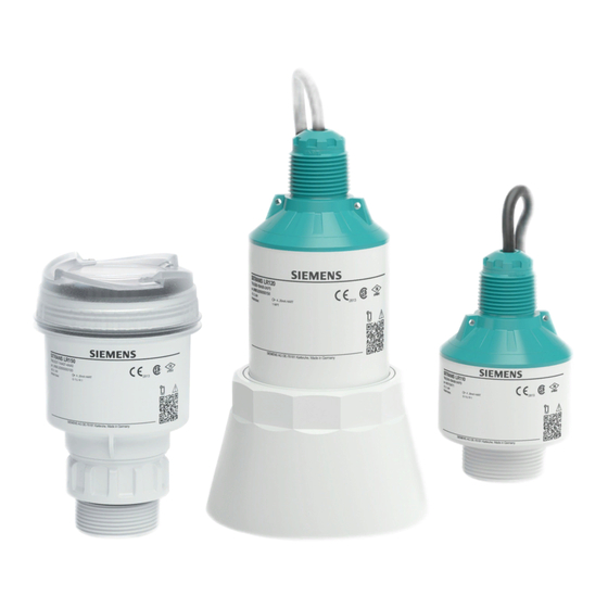
Description 3.2 Principle of operation Constituent parts Radar antenna Electronics housing Mounting thread Connection cable Figure 3.1 Components of SITRANS LR120 Nameplate The nameplate contains the most important data for identification and use of the transmitter. Transmitter type Serial number Technical data Field for approvals QR code for device documentation Wireless access via smartphone... -
Page 14: Adjustment
Description 3.3 Adjustment Functional principle The transmitter emits a continuous, frequency-modulated radar signal through its antenna. The emitted signal is reflected by the medium and received by the antenna as an echo with modified frequency. The frequency change is proportional to the distance and is converted into the level. -
Page 15: Packaging, Transport And Storage
Description 3.4 Packaging, transport and storage Figure 3.4 Connecting the PC to the signal cable Packaging, transport and storage Packaging Your transmitter was protected by packaging during transport. Its capacity to handle normal loads during transport is assured by a test based on ISO 4180. The packaging consists of environment-friendly, recyclable cardboard. -
Page 16: Accessories
Description 3.5 Accessories Accessories Mounting accessories The optional mounting accessories include bracket and mounting bracket and are used for stable mounting of the transmitter at the measuring point. The parts are available in various versions and sizes. SITRANS LR120 Operating Instructions, 01/2020, A5E49829026... - Page 17 Description 3.5 Accessories SITRANS LR120 Operating Instructions, 01/2020, A5E49829026...
-
Page 18: Installing/Mounting
Installing/mounting General instructions Ambient conditions The transmitter is suitable for standard and extended ambient conditions acc. to DIN/ EN/IEC/ANSI/ISA/UL/CSA 61010-1. It can be used indoors as well as outdoors. Process conditions WARNING For safety reasons, the transmitter must only be operated within the permissible process conditions. -
Page 19: Mounting Instructions
Installing/mounting 4.3 Mounting instructions Figure 4.1 Mounting via a mounting bracket Mounting instructions Installation position When mounting the transmitter, keep a distance of at least 200 mm (7.874 in) from the vessel wall. If the transmitter is installed in the center of dished or round vessel tops, multiple echoes can arise. - Page 20 Installing/mounting 4.3 Mounting instructions Figure 4.3 Reference point Inflowing medium Do not mount the transmitters in or above the filling stream. Make sure that you de- tect the product surface, not the inflowing product. Figure 4.4 Mounting of the radar transmitter with inflowing medium Mounting nozzle For nozzle mounting, the nozzle should be as short as possible and its end rounded.
- Page 21 Installing/mounting 4.3 Mounting instructions Figure 4.6 Nozzle mounting with deviating nozzle dimensions Nozzle diameter d Nozzle length h 80 mm 3" ≤ 300 mm ≤ 11.8 in 100 mm 4" ≤ 400 mm ≤ 15.8 in 150 mm 6" ≤ 600 mm ≤ 23.6 in Transmitter orientation In liquids, direct the transmitter as perpendicular as possible to the product surface to achieve optimum measurement results.
-
Page 22: Measurement Setup - Flow
Installing/mounting 4.4 Measurement setup - Flow Foam generation Through the action of filling, stirring and other processes in the vessel, compact foams which considerably damp the emitted signals may form on the product sur- face. If foams lead to measurement errors, you should use transmitters with guided radar. - Page 23 Installing/mounting 4.4 Measurement setup - Flow Khafagi-Venturi flume Position transmitter Venturi flume Figure 4.10 Flow measurement with Khafagi-Venturi flume: h = max. filling of the flume; B = max. tightest constriction in the flume SITRANS LR120 Operating Instructions, 01/2020, A5E49829026...
-
Page 24: Connecting
Connecting Preparing the connection Safety instructions Always keep in mind the following safety instructions: • Carry out electrical connection by trained, qualified personnel authorised by the plant operator • If overvoltage surges are expected, overvoltage arresters should be installed WARNING Only connect or disconnect in de-energized state. -
Page 25: Wiring Plan
Connecting 5.2 Wiring plan Cable screening and grounding If shielded cable is required, we recommend that the cable screening be connected to ground potential on one side of the supply side. In Ex systems, the grounding is carried out according to the installation regulations. Wiring plan Wire assignment, connection cable Figure 5.1... -
Page 26: Access Protection
Access protection Bluetooth radio interface Devices with a Bluetooth radio interface are protected against unwanted access from outside. This means that only authorized persons can receive measured and status values and change device settings via this interface. Bluetooth PIN A Bluetooth PIN is required to establish Bluetooth communication via the adjustment tool (smartphone/tablet/notebook). - Page 27 Access protection 6.2 Protection of the parameterization Device Access PUK The Device Access PUK allows unlocking the device in case the user PIN is no longer known. It can't be changed. The Device Access PUK can also be found on the supplied information sheet "Device Bluetooth and Parameter Access Codes".
-
Page 28: Setup With Smartphone/Tablet (Bluetooth)
Setup with smartphone/tablet (Bluetooth) Connecting Connecting Start the adjustment app. The smartphone/tablet searches automatically for Blue- tooth-capable transmitters in the area. The devices found are listed. Select the requested transmitter in the device list. Authenticate For the first connection, the adjustment tool and the transmitter must authenticate each other. - Page 29 Setup with smartphone/tablet (Bluetooth) 7.1 Connecting SITRANS LR120 Operating Instructions, 01/2020, A5E49829026...
-
Page 30: Setup With Pc/Notebook (Hart Modem)
Setup with PC/notebook (HART modem) Saving the parameterisation data We recommend documenting or saving the parameterisation data via SIMATIC PDM. That way the data are available for multiple use or service purposes. SITRANS LR120 Operating Instructions, 01/2020, A5E49829026... - Page 31 Setup with PC/notebook (HART modem) 8.1 Saving the parameterisation data SITRANS LR120 Operating Instructions, 01/2020, A5E49829026...
-
Page 32: Device Configuration
Device configuration To configure the device: Download and install the SITRANS mobile IQ app from the App store to your mo- bile device. Launch the app. Devices in range will appear. Click on the device you wish to connect to. On first connection, a PIN code shipped with the device needs to be entered (see Device Bluetooth and Parame- SITRANS LR120 Operating Instructions, 01/2020, A5E49829026... - Page 33 Device configuration ter Access Codes sheet). Following successful PIN entry, the device cockpit will be shown. SITRANS LR120 Operating Instructions, 01/2020, A5E49829026...
- Page 34 Device configuration Use the Setup/Quick Commissioning to configure the transmitter for your appli- cation type. SITRANS LR120 Operating Instructions, 01/2020, A5E49829026...
- Page 35 Device configuration Many diagnostic tools are supported, including the echo profile viewer: SITRANS LR120 Operating Instructions, 01/2020, A5E49829026...
-
Page 36: Set Up With Other Systems
Set up with other systems 10.1 Setup with SIMATIC PDM EDD Device descriptions as Enhanced Device Description (EDD) are available for DD adjust- ment programs such as for example PDM. SITRANS LR120 Operating Instructions, 01/2020, A5E49829026... - Page 37 Set up with other systems 10.1 Setup with SIMATIC PDM EDD SITRANS LR120 Operating Instructions, 01/2020, A5E49829026...
-
Page 38: Diagnostics And Servicing
Diagnostics and servicing 11.1 Maintenance Maintenance If the device is used properly, no special maintenance is required in normal opera- tion. Precaution measures against buildup In some applications, buildup on the antenna system can influence the measuring result. Depending on the transmitter and application, take measures to avoid heavy soiling of the antenna system. -
Page 39: Diagnosis, Fault Messages
Diagnostics and servicing 11.3 Diagnosis, fault messages • Signal processing Fault rectification The first measures are: • Evaluation of fault messages • Checking the output signal • Treatment of measurement errors A smartphone/tablet with the adjustment app or a PC/notebook with the PDM and the suitable EDD offer you further comprehensive diagnostic possibilities. - Page 40 Diagnostics and servicing 11.4 Status messages according to NE 107 Status messages The status messages are divided into the following categories: • Failure • Function check • Out of specification • Maintenance requirement and explained by pictographs: Failure - red Out of specification - yellow Function check - orange Maintenance - blue Figure 11.1...
- Page 41 Diagnostics and servicing 11.4 Status messages according to NE 107 Code Cause Rectification DevSpec Text message State in CMD 48 F017 Adjustment not within Change adjustment Byte 5, Bit 1 of specification according to the limit Byte 0 … 5 Adjustment span too values (difference be- small tween min.
- Page 42 Diagnostics and servicing 11.4 Status messages according to NE 107 Out of specification Code Cause Rectification DevSpec Text message State in CMD 48 S600 Temperature of the Check ambient temper- Byte 23, Bit 4 of electronics in the non- ature Byte 14 … 24 Impermissible electron- specified range ics temperature Insulate electronics S601...
-
Page 43: Treatment Of Measurement Errors
Diagnostics and servicing 11.5 Treatment of measurement errors Code Cause Rectification DevSpec Text message State in CMD 48 M510 Bit 10 of Byte 14 … 24 No communication with the transmitter 11.5 Treatment of measurement errors The tables below give typical examples of application-related measurement errors. The images in column "Error description"... - Page 44 Diagnostics and servicing 11.5 Treatment of measurement errors Fault description Cause Rectification Max. adjustment not correct Check measuring point: Anten- na should protrude out of the threaded mounting nozzle, pos- sible false echoes through flange nozzle? Remove contamination on the antenna In case of interferences due to installations in the close range, change polarisation direction...
- Page 45 Diagnostics and servicing 11.5 Treatment of measurement errors Fault description Cause Rectification After eliminating the false sig- nals, the auto false echo sup- pression must be deleted. Carry out a new auto false echo sup- pression Measured value jumps sporadi- Varying condensation or conta- Carry out auto false echo sup- cally towards 100 % during emp- mination on the antenna...
- Page 46 Diagnostics and servicing 11.5 Treatment of measurement errors Fault description Cause Rectification Transverse reflection from an ex- Direct transmitter to the oppo- traction funnel, amplitude of the site funnel wall, avoid crossing transverse reflection larger than with the filling stream the level echo Measured value fluctuates Various echoes from an uneven Check parameter "Material Type"...
-
Page 47: Return Procedure
Reason for returning the item(s) • Decontamination declaration • https://www.siemens.com/sc/declarationofdecontamination With this declaration you warrant "that the device/replacement part has been careful- ly cleaned and is free of residues. The device/replacement part does not pose a haz- ard for humans and the environment."... -
Page 48: Technical Support
DVD. 11.8 How to proceed if a repair is necessary If it is necessary to repair the transmitter, please contact Siemens. You find the loca- tions on "www.siemens.com/processautomation [https:://www.siemens.com/proces- sautomation]". SITRANS LR120 Operating Instructions, 01/2020, A5E49829026... - Page 49 Diagnostics and servicing 11.8 How to proceed if a repair is necessary SITRANS LR120 Operating Instructions, 01/2020, A5E49829026...
-
Page 50: Service And Maintenance
Devices can be returned to the supplier within the EC, or to a locally approved dis- posal service for eco-friendly recycling. Observe the specific regulations valid in your country. Further information about devices containing batteries can be found at: (https://sup- port.industry.siemens.com/cs/document/109479891/) Note Special disposal required The device includes components that require special disposal. •... - Page 51 Service and maintenance 12.2 Disposal SITRANS LR120 Operating Instructions, 01/2020, A5E49829026...
-
Page 52: Technical Data And Dimensions
Technical data Note for approved transmitters Device specifications: Siemens makes every effort to ensure the accuracy of these specifications, but re- serves the right to change them at any time. Device-specific approvals: The device-specific approvals are always to be found on the type plates on the de- vice. - Page 53 Technical data and dimensions 13.1 Technical data Input variable Measured variable The measured variable is the distance between the antenna edge of the transmitter and the product surface. The antenna edge is also the reference point for the measurement. Max. measuring 30 m (98.43 ft) range Depending on application and medium...
- Page 54 Technical data and dimensions 13.1 Technical data Deviation (according to DIN EN 60770-1) Deviation with liquids ≤ 2 mm (meas. distance > 0.25 m/0.8202 ft) Non-repeatability ≤ 2 mm Deviation with bulk The values depend to a great extent on the application. Binding specifica- solids tions are thus not possible. Already included in the meas.
- Page 55 Technical data and dimensions 13.1 Technical data Beam angle 4° With operating voltage U ≥ 24 V DC Time span after a sudden distance change from 1 m to 5 m until the output signal reaches 90 % of the final value for the first time (IEC 61298-2). Valid with operating voltage U ≥ 24 V DC.
-
Page 56: Dimensions
Technical data and dimensions 13.2 Dimensions Altitude above sea lev- 5000 m (16404 ft) Protection class Pollution degree 13.2 Dimensions Figure 13.1 Dimensions SITRANS LR120 13.3 License information for Open Source Software Hashfunction acc. to mbed TLS: Copyright (C) 2006-2015, ARM Limited, All Rights Re- served SPDX-License-Identifier: Apache-2.0 Licensed under the Apache License, Version 2.0 (the "License");... - Page 57 Technical data and dimensions 13.4 Trademark SITRANS LR120 Operating Instructions, 01/2020, A5E49829026...
- Page 58 Further Information Process Automation https://www.siemens.com/processautomation Industry Online Support (service and support) https://support.industry.siemens.com Industry Mall https://mall.industry.siemens.com Siemens AG Digital Industry Process Automation Postfach 48 48 90026 NÜRNBERG GERMANY...
Need help?
Do you have a question about the SITRANS L Series and is the answer not in the manual?
Questions and answers