
Related Manuals for Planet VC-2400MR


Summary of Contents for Planet VC-2400MR
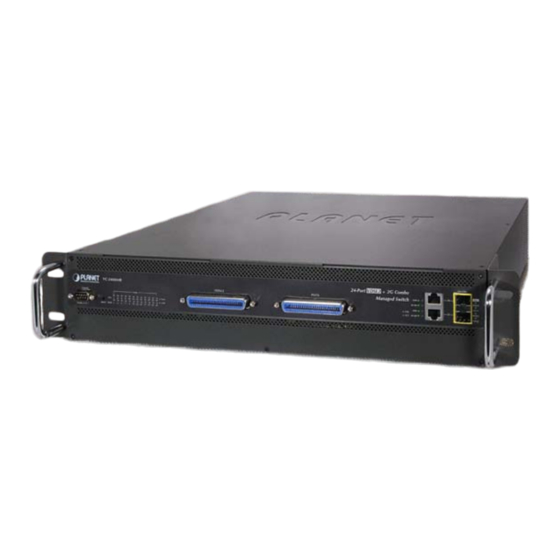
- Page 1 User’s Manual of VC-820M User’s Manual VC-2400MR VC-2400MR48 24-Port VDSL2 + 2G TP/SFP Combo Managed Switch VC-820M 8-Port VDSL2 + 2G TP/SFP Combo Managed Switch...
- Page 2 PLANET is a registered trademark of PLANET Technology Corp. All other trademarks belong to their respective owners. Disclaimer PLANET Technology does not warrant that the hardware will work properly in all environments and applications, and makes no warranty and representation, either implied or expressed, with respect to the quality, performance, merchantability, or fitness for a particular purpose.
-
Page 3: Table Of Contents
User’s Manual of VC-820M / VC-2400MR Series TABLE OF CONTENTS 1. INTRODUCTION ......................8 1.1 Package Contents ..........................8 1.2 Product Description.......................... 10 1.3 How to Use This Manual........................12 1.4 Product Features..........................13 1.5 Product Specification ........................15 2. INSTALLATION......................18 2.1 Hardware Description ........................ - Page 4 User’s Manual of VC-820M / VC-2400MR Series 4.2.2 IP Configuration ......................... 48 4.2.3 Console Information ........................50 4.2.4 SNMP Configuration........................50 4.2.5 Firmware Upgrade........................58 4.2.6 Configuration Backup ........................ 60 4.2.7 Factory Default .......................... 63 4.2.8 System Reboot .......................... 63 4.2.9 Syslog Setting..........................
- Page 5 User’s Manual of VC-820M / VC-2400MR Series 4.8.4 STP System Configuration ...................... 109 4.8.5 Port Configuration........................112 4.9 DHCP Relay & Option 82 ........................ 114 4.10 LLDP ............................... 116 4.10.1 LLDP Configuration ....................... 116 4.10.2 PerPort Configuration ......................117 4.11 Access Control List ........................118 4.12 Security Manager ..........................
- Page 6 User’s Manual of VC-820M / VC-2400MR Series 6.5.1 Virtual LANs..........................160 6.5.2 VLAN Mode: Port-based......................161 6.5.3 Advanced 802.1Q VLAN Configuration................... 162 6.6 Misc Configuration.......................... 165 6.7 Administration Configuration ......................166 6.7.1 Change Username / Password....................166 6.7.2 IP Configuration ........................167 6.7.3 Reboot switch ..........................
- Page 7 8. TROUBLE SHOOTING..................... 208 APPENDIX A—RJ-45 PIN ASSIGNMENT ..............210 A.1 Switch's RJ-45 Pin Assignments ....................210 A.2 10/100Mbps, 10/100Base-TX......................210 A.3 RJ-21 Connector pin out for VC-2400MR Series ................. 212 A.4 RJ-21 / Telco 50 Cable pin out ...................... 213...
-
Page 8: Introduction
User’s Manual of VC-820M / VC-2400MR Series 1. Introduction The PLANET Layer 2 Managed Switch series - VC-2400MR, VC-2400MR48, VC-820M are multiple VDSL2 ports Ethernet Switched with Gigabit TP/SFP fiber optical combo connective ability and robust layer 2 features; the description of these... - Page 9 User’s Manual of VC-820M / VC-2400MR Series VC-2400MR or VC-2400MR48 comes with one power system by default. The power slot 2 is vacant slot and can be installed with MC-RPS130 or MC-RPS48, please consult your local dealer for the order information.
-
Page 10: Product Description
High Performance VDSL2 Data Rate over Existing Phone Lines PLANET VC-2400MR Series and VC-820M are multiple ports VDSL2 Managed CO Switch (Central Office) for Telecom, ISP (Internet Service Provider), SI (System Integration), IP Surveillance provider and etc. It is based on two core networking technology, Ethernet and VDSL2 (Very-high-data-rate Digital Subscriber Line 2). - Page 11 ISP can immediately and remotely upgrade/downgrade bandwidth service by different demand. Efficient Management Afford the current network to grow and expand, the PLANET VC-2400MR series and VC-820M provide console and telnet command line interface, advanced WEB and SNMP management interface to fill this kind of demand. With its built-in Web-based management, the VDSL2 Switch offers an easy-to-use, platform-independent management and configuration facility.
-
Page 12: How To Use This Manual
User’s Manual of VC-820M / VC-2400MR Series Temperature and FAN Status Monitoring - The Managed VDSL2 Switch is equipped with temperature senor and cooling fans to ensure reliable operation. Whenever the abnormal temperature is detected or cooling fan stops service, the Managed Media Converter Chassis would display related information on the Web management interface. -
Page 13: Product Features
User’s Manual of VC-820M / VC-2400MR Series 1.4 Product Features VDSL Interface VC-2400MR / VC-2400MR48 24 Full-Duplex VDSL links via RJ-21(Telco-50) connector 24 corresponding POTS lines via RJ-21(Telco-50) connector Built-in POTS splitter for each VDSL port Auto-speed function for VDSL2 link (by distance and cable quality) - Page 14 User’s Manual of VC-820M / VC-2400MR Series • STP, IEEE 802.1D (Classic Spanning Tree Protocol) • MSTP, IEEE 802.1s (Multiple Spanning Tree Protocol, spanning tree by VLAN) Quality of Service 4 priority queues on all switch ports Traffic classification: • IEEE 802.1p Class of Service •...
-
Page 15: Product Specification
User’s Manual of VC-820M / VC-2400MR Series 1.5 Product Specification Product VC-820M VC-2400MR VC-2400MR48 Hardware Specification 8-Port VDSL2 24-Port VDSL2 RJ-11 connectors RJ-21(Telco-50) connectors VDSL2 Interface 8-Port POTS/Telephone 24-Port POTS/Telephone RJ-11 connectors RJ-21(Telco-50) connectors 2 10/100/1000Mbps RJ-45 Auto-MDI/MDI-X ports 1000Mbps Copper Ports... - Page 16 User’s Manual of VC-820M / VC-2400MR Series 1000Base-T: 4-pair UTP Cat 5E, up to 100m 。 1000Base-SX: 50/125μm and 62.5/125μm fiber-optic cable, up to 550m 。 1000Base-LX: 9/125μm fiber optic cable, from 10km to 120km 。 VDSL2 Comply with ITU-T G.993.1 and G.993.2.
- Page 17 User’s Manual of VC-820M / VC-2400MR Series IGMP (v1/v2) Snooping, up to 256 multicast Groups IGMP Snooping IP-Based Layer 3 / Layer 4 ACL Access Control List Up to 220 ACL rule entries RFC-1213 MIB-II RFC-2863 Interface MIB RFC-2665 EtherLike MIB...
-
Page 18: Installation
There are 24 VDSL2 ports and 24 POTS ports with 2 Telco-50 / RJ-21 type connectors on the front panel of VC-2400MR series and there are 8 VDSL2 ports and 8 POTS ports with RJ-11 phone connectors on the front panel of VC-820M. - Page 19 User’s Manual of VC-820M / VC-2400MR Series The VDSL2 supports auto detection transmission rate that operate in different band allocation and result in different upstream and downstream bandwidth. And Due to different telephone line quality, cross talk or extension distance may affect actual achievable speed;...
-
Page 20: Led Indications
The front panel LEDs indicates instant status of port links, data activity and system power; helps monitor and troubleshoot when needed. VC-2400MR Series LED indication Figure 2-1-3: VC-2400MR Series System and Port LED panel Figure 2-1-4: VC-2400MR Series Power and fan LED panel ■ System... - Page 21 User’s Manual of VC-820M / VC-2400MR Series ■ 10/100/1000Base-T Copper / 1000Base-SX/LX SFP Interface (Port-25 and Port-26) Color Function To indicate the link through that port is successfully established with speed 1000Mbps Blink: To indicate that the switch is actively sending or receiving data over that port.
- Page 22 If 1000 LNK/ACT LED is Off, it indicates that the port is link down The 2 Gigabit TP/SFP combo ports are shared with Port 9/10 of VC-820M or Port25/26 of VC-2400MR Series. Either of them can operate at the same time.
-
Page 23: Switch Rear Panel
Figure 2-1-8: VC-2400MR48 rear panel with DC power module Install and remove the power supply unit To install a power supply unit to VC-2400MR series, please fasten the hand screw clockwise and slide in the power supply unit to the Managed Media Converter Chassis. - Page 24 User’s Manual of VC-820M / VC-2400MR Series The rear panel of VC-8 20M indicates an AC inlet power socket, which accepts input power from 100 t o 240V AC, 50-60Hz. Figure 2-1-10 shows the rear panel of the Managed Switch.
-
Page 25: Install The Switch
User’s Manual of VC-820M / VC-2400MR Series 2.2 Install the Switch This section describes how to install the Managed Switch and make connections to it. Please read the following topics and perform the procedures in the order being presented. 2.2.1 Desktop Installation To install the Managed Switch on desktop or shelf, please follows these steps: Step1: Attach the rubber feet to the recessed areas on the bottom of the Managed Switch. -
Page 26: Rack Mounting
User’s Manual of VC-820M / VC-2400MR Series 2.2.2 Rack Mounting To install the Managed Switch in a 19-inch standard rack, please follows the instructions described below. Step1: Place the Managed Switch on a hard flat surface, with the front panel positioned towards the front side. - Page 27 User’s Manual of VC-820M / VC-2400MR Series Figure 2-2-3: Mounting the VC-2400MR series in a Rack Figure 2-2-4: Mounting the VC-820M in a Rack Step6: Proceeds with the steps 4 and steps 5 of session 2.2.1 Desktop Installation to connect the network cabling and...
-
Page 28: Installing The Sfp Transceiver
Figure 2-2-5: Plug-in the SFP transceiver Approved PLANET SFP Transceivers PLANET Managed switches supports both single mode and multi mode SFP transceiver. The following list of approved PLANET SFP transceivers is correct at the time of publication: 1000Base-SX/LX SFP transceiver: MGB-SX SFP (1000BASE-SX SFP transceiver –... - Page 29 User’s Manual of VC-820M / VC-2400MR Series Check the fiber-optic cable type match the SFP transceiver model. To connect to 1000Base-SX SFP transceiver, use the multi-mode fiber cable- with one side must be male duplex LC connector type. To connect to 1000Base-LX SFP transceiver, use the single-mode fiber cable-with one side must be male duplex LC connector type.
-
Page 30: Wiring For Vdsl2 Ports
2.3 Wiring for VDSL2 Ports The VDSL2 port of VC-2400MR series uses one RJ-21 (Telco 50) connector to connect to a patch panel then link up to 24 VDSL CPEs and the VDSL2 port of VC-820M uses eight RJ-11 connectors which can be just directly connected to the remote CPEs (VC-230, VC-230N, VC-231, VC-234 or other compatible CPE) through structured or unstructured wiring, such as existing telephone lines. - Page 31 User’s Manual of VC-820M / VC-2400MR Series Figure 2-3-2 Telco RJ-21 connect to VC-2400MR series Figure 2-3-3: VC-2400MR Series VDSL2 connection...
- Page 32 User’s Manual of VC-820M / VC-2400MR Series VC-820M VDSL2 connection The VDSL2 port of VC-820M uses eight RJ-11 connectors which can be just directly connected to the remote CPEs through existing telephone lines. Figure 2-3-4: VC-820M VDSL2 connection If the port is connected but the relevant LED is dark, check the following items: The VDSL2 Switch and the connected device’s power are on or not.
-
Page 33: Switch Management
User’s Manual of VC-820M / VC-2400MR Series 3. SWITCH MANAGEMENT This chapter explains the methods that you can use to configure management access to the Managed Switch. It describes the types of management applications and the communication and management protocols that deliver data between your management device (work-station or personal computer) and the system. -
Page 34: Management Access Overview
User’s Manual of VC-820M / VC-2400MR Series 3.2 Management Access Overview The Managed Switch gives you the flexibility to access and manage it using any or all of the following methods: Web browser interface An external SNMP-based network management application... -
Page 35: Web Management
User’s Manual of VC-820M / VC-2400MR Series 3.3 Web Management The Managed Switch offers management features that allow users to manage the Managed Switch from anywhere on the network through a standard browser such as Microsoft Internet Explorer. After you set up your IP address for the switch, you can access the Managed Switch's Web interface applications directly in your Web browser by entering the IP address of the Managed Switch. -
Page 36: Snmp-Based Network Management
User’s Manual of VC-820M / VC-2400MR Series 3.4 SNMP-Based Network Management You can use an external SNMP-based application to configure and manage the Managed Switch, such as SNMPc Network Manager, HP Openview Network Node Management (NNM) or What’sup Gold. This management method requires the SNMP agent on the switch and the SNMP Network Management Station to use the same community string. - Page 37 User’s Manual of VC-820M / VC-2400MR Series Direct Access Direct access to the administration console is achieved by directly connecting a terminal or a PC equipped with a terminal-emulation program (such as HyperTerminal) to the Managed Switch console (serial) port.
-
Page 38: Protocols
User’s Manual of VC-820M / VC-2400MR Series 3.6 Protocols The Managed Switch supports the following protocols: Virtual terminal protocols, such as Telnet Simple Network Management Protocol (SNMP) 3.6.1 Virtual Terminal Protocols A virtual terminal protocol is a software program, such as Telnet, that allows you to establish a management session from a Macintosh, a PC, or a UNIX workstation. -
Page 39: Web-Based Management
User’s Manual of VC-820M / VC-2400MR Series 4. Web-Based Management This section introduces the configuration and functions of the Web-Based management. 4.1 About Web-based Management The Managed Switch offers management features that allow users to manage the Managed Switch from anywhere on the network through a standard browser such as Microsoft Internet Explorer. -
Page 40: Requirements
Network cables - Use standard network (UTP) cables with RJ45 connectors. Above PC installed with WEB Browser and JAVA runtime environment Plug-in. It is recommended to use Internet Explore 6.0 or above to access VC-820M /VC-2400MR series Managed Switch. 4.1.2 Logging on the switch Use Internet Explorer 6.0 or above Web browser. - Page 41 For security reason, please change and memorize the new password after this first setup. The WEB configuration and CLI command of VC-820M are the same with VC-2400MR series except Power/Fan module detection feature, so the VC-820M will be the example to...
-
Page 42: Main Web Page
User’s Manual of VC-820M / VC-2400MR Series 4.1.3 Main WEB PAGE The Managed Switch provides a Web-based browser interface for configuring and managing it. This interface allows you to access the Managed Switch using the Web browser of your choice. This chapter describes how to use the Managed Switch’s Web browser interface to configure and manage it. -
Page 43: System
Main Function. The screen in Figure 4-1-4 appears. Figure 4-1-4: VC-820M / VC-2400MR series Managed Switch Main Functions Menu 4.2 System Use the System menu items to display and configure basic administrative details of the Managed Switch. Under System the following topics are provided to configure and view the system information: This section has the following items: Provides basic system description, including contact information. -
Page 44: System Information
User’s Manual of VC-820M / VC-2400MR Series 4.2.1 System Information In System information, it has two parts of setting – Basic and Misc Config. We will describe the configure detail in following. 4.2.1.1 Basic The Basic System Info page provides information for the current device information. Basic System Info page helps a switch administrator to identify the model name, firmware / hardware version and MAC address. - Page 45 User’s Manual of VC-820M / VC-2400MR Series 4.2.1.2 Misc Config Choose Misc Config from System Information of Managed Switch, the screen in Figure 4-2-2 appears. Figure 4-2-2: Switch Misc Config screenshot The page includes the following fields: Object Description Type the number of seconds that an inactive MAC address remains in the MAC Address Age-out switch’s address table.
- Page 46 802.1x protocol Press the button to complete the configuration. Apply button 4.2.1.3 Module Info This section provides current status of power supply unit from VC-2400MR series, the screen in Figure 4-2-3 appears and table 4-2-1 describes the power and fan module Status object of VC-2400MR series.
- Page 47 Red: Power Type AC: indicate the AC power supply unit (MC-RPS90) install into the VC-2400MR series. DC: indicate the DC power supply unit (MC-RPS48) install into the VC-2400MR series. Fan Status indicate the power supply unit not install into the VC-2400MR series.
-
Page 48: Ip Configuration
User’s Manual of VC-820M / VC-2400MR Series 4.2.2 IP Configuration The Managed Switch is a network device which needs to be assigned an IP address for being identified on the network. Users have to decide a means of assigning IP address to the Managed Switch. - Page 49 User’s Manual of VC-820M / VC-2400MR Series The page includes the following fields: Object Description Enable or disable the DHCP client function. When DHCP function is enabled, the Managed Switch will be assigned an IP address from the network DHCP server. The default IP address will be replaced DHCP by the assigned IP address on DHCP server.
-
Page 50: Console Information
User’s Manual of VC-820M / VC-2400MR Series 4.2.3 Console Information Console is a standard UART interface to communicate with Serial Port. You can use Windows HyperTerminal program to link the Managed Switch. The page displays the required console settings on the Managed Switch. - Page 51 User’s Manual of VC-820M / VC-2400MR Series Get -- Allows the NMS to retrieve an object instance from the agent. Set -- Allows the NMS to set values for object instances within an agent. Trap -- Used by the agent to asynchronously inform the NMS of some event. The SNMPv2 trap message is designed to replace the SNMPv1 trap message.
- Page 52 User’s Manual of VC-820M / VC-2400MR Series Indicates the SNMP mode operation. Possible modes are: SNMP Status • Enabled: Enable SNMP mode operation. • Disabled: Disable SNMP mode operation. 4.2. 4. 3 Community Strings Community strings serve as passwords and can be entered as one of the following:...
- Page 53 User’s Manual of VC-820M / VC-2400MR Series 4.2. 4 .4 Trap Managers A trap manager is a management station that receives the trap messages generated by the switch. If no trap manager is defined, no traps will be issued. To define a management station as a trap manager, assign an IP address, enter the SNMP community strings, and select the SNMP trap version.
- Page 54 User’s Manual of VC-820M / VC-2400MR Series The page includes the following fields: Object Description A string identifying the group name that this entry should belong to. Group Name: The allowed string length is 1 to 15. Indicates the security model that this entry should belong to. Possible security...
- Page 55 User’s Manual of VC-820M / VC-2400MR Series • included: An optional flag to indicate that this view subtree should be included. • excluded: An optional flag to indicate that this view subtree should be excluded. The OID defining the root of the subtree to add to the named view. The allowed View Subtree OID length is 1 to 128.
- Page 56 User’s Manual of VC-820M / VC-2400MR Series • NoAuth: None authentication and none privacy. • Auth: Authentication and none privacy. • Authpriv: Authentication and privacy. The name of the MIB views defining the MIB objects for which this request may request the current values.
- Page 57 User’s Manual of VC-820M / VC-2400MR Series The value of security level cannot be modified if entry already exist. That means must first ensure that the value is set correctly. A string identifying the authentication pass phrase. Auth Key(8~32): For MD5 authentication protocol, the allowed string length is 8 to 32.
-
Page 58: Firmware Upgrade
User’s Manual of VC-820M / VC-2400MR Series 4.2.5 Firmware Upgrade It provides the functions allowing the user to update the switch firmware via the Trivial File Transfer Protocol (TFTP) server. Before updating, make sure the TFTP server is ready and the firmware image is located on the TFTP server. - Page 59 User’s Manual of VC-820M / VC-2400MR Series 4.2.5.2 HTTP Firmware Upgrade The HTTP Firmware Upgrade page contains fields for downloading system image files from the Local File browser to the device. The Web Firmware Upgrade screen in Figure 4-2-14 appears.
-
Page 60: Configuration Backup
User’s Manual of VC-820M / VC-2400MR Series Select on the firmware then click “Submit”, the Software Upload Progress would show the file upload status. Firmware upgrade needs several minutes. Please wait a while, and then manually refresh the webpage. 4.2.6 Configuration Backup 4.2.6.1 TFTP Restore Configuration... - Page 61 User’s Manual of VC-820M / VC-2400MR Series 4.2.6.2 HTTP Config File Restore You can also restore the previous backup configuration from the current workstation utilize internet browser such as Microsoft Internet Explore or Mozila Firefox, to recover the settings. Before doing that, you must locate the image file on the...
- Page 62 User’s Manual of VC-820M / VC-2400MR Series 4.2.6.4 HTTP Config File Backup This function allows backup the current configuration of the Managed Switch to the local management station. The screens Figure 4-2-19 and Figure 4-2-20 appear. Figure 4-2-19: HTTP configuration file backup interface Move the cursor to “Click here to download configuration...
-
Page 63: Factory Default
User’s Manual of VC-820M / VC-2400MR Series 4.2.7 Factory Default Reset switch to default configuration. Click to reset all configurations to the default value. Figure 4-2-21: Factory Default interface 4.2.8 System Reboot Reboot Reboot the switch in software reset. Click to reboot the system. -
Page 64: Syslog Setting
User’s Manual of VC-820M / VC-2400MR Series 4.2.9 Syslog Setting The Syslog Setting page allows you to configure the logging of messages that are sent to remote syslog servers or other management stations. You can also limit the event messages sent to only those messages below a specified level. -
Page 65: Port Configuration
User’s Manual of VC-820M / VC-2400MR Series 4.3 Port Configuration Use the Port Configuration Menu to display or configure the Managed Switch’s ports. This section has the following items: Configures port connection settings Port Control Display the current Port link status and speed etc. - Page 66 User’s Manual of VC-820M / VC-2400MR Series the Negotiation column is set as Auto, this column is read-only. The item is only for Gigabit ports of the Managed Switch. Duplex: It is available for selecting when the Negotiation column is set as Force. When the Negotiation column is set as Auto, this column is read-only.
-
Page 67: Port Status
User’s Manual of VC-820M / VC-2400MR Series 4.3.2 Port Status This page displays current port configurations and operating status - it is a ports’ configurations summary table. Via the summary table, you can know status of each port clear at a glance, like Port Link Up/Link Down status, negotiation, Link Speed, Rate Control, Duplex mode and Flow Control. -
Page 68: Port Sniffer
User’s Manual of VC-820M / VC-2400MR Series The page includes the following fields: Object Description The port number. Port: It’s set by Port Control. When the state is disabled, the port will not transmit or State: receive any packet. The status of linking—‘Up’ or ‘Down’. - Page 69 User’s Manual of VC-820M / VC-2400MR Series Configuring the port mirroring by assigning a source port from which to copy all packets and a destination port where those packets will be sent. Figure 4-3-5: Port Sniffer interface The page includes the following fields:...
-
Page 70: Protect Port
User’s Manual of VC-820M / VC-2400MR Series 4.3.5 Protect Port There are two protected port groups; ports in different groups can't communicate. In the same group, protected ports can't communicate with each other, but can communicate with unprotected ports. Unprotected ports can communicate with any ports, including protected ports. -
Page 71: Vlan Configuration
User’s Manual of VC-820M / VC-2400MR Series 4.4 VLAN configuration 4.4.1 VLAN Overview A Virtual Local Area Network (VLAN) is a network topology configured according to a logical scheme rather than the physical layout. VLAN can be used to combine any collection of LAN segments into an autonomous user group that appears as a single LAN. - Page 72 User’s Manual of VC-820M / VC-2400MR Series VLAN can also provide a level of security to your network. IEEE 802.1Q VLAN will only deliver packets between stations that are members of the VLAN. Any port can be configured as either tagging or untagging. The untagging feature of IEEE 802.1Q VLAN allows VLAN to work with legacy switches that don't recognize VLAN tags in packet headers.
- Page 73 User’s Manual of VC-820M / VC-2400MR Series Adding an IEEE802.1Q Tag Original Ethernet Dest. Src. Length/E. Data Old CRC Addr. Addr. type Dest. Addr. Src. Addr. Length/E. type Data New CRC E. type New Tagged Packet Priority VLAN ID Port VLAN ID Packets that are tagged (are carrying the 802.1Q VID information) can be transmitted from one 802.1Q compliant network...
-
Page 74: Static Vlan Configuration
User’s Manual of VC-820M / VC-2400MR Series with VLAN already in place, you will not need to reconfigure the VLAN settings after changing the port link aggregation group settings. VLAN settings will automatically change in conjunction with the change of the port link aggregation group settings. -
Page 75: Port-Based Vlan
User’s Manual of VC-820M / VC-2400MR Series 4.4.3 Port-based VLAN Packets can go among only members of the same VLAN group. Note all unselected ports are treated as belonging to another single VLAN. If the port-based VLAN enabled, the VLAN-tagging is ignored. - Page 76 User’s Manual of VC-820M / VC-2400MR Series Figure 4-4-3: Static VLAN interface The page includes the following fields: Object Description Use this optional field to specify a name for the VLAN. It can be up to 16 VLAN Name alphanumeric characters long, including blanks.
-
Page 77: Q Vlan
User’s Manual of VC-820M / VC-2400MR Series 4.4.4 802.1Q VLAN Tagged-based VLAN is an IEEE 802.1Q specification standard. Therefore, it is possible to create a VLAN across devices from different switch venders. IEEE 802.1Q VLAN uses a technique to insert a "tag" into the Ethernet frames. Tag contains a VLAN Identifier (VID) that indicates the VLAN numbers. - Page 78 User’s Manual of VC-820M / VC-2400MR Series 4.4.4.1 VLAN Group Configuration VLAN Group Configuration Figure 4-4-4: VLAN Group Configuration interface Click the hyperlink "VLAN” \ “Static VLAN" to enter the VLAN configuration interface. Select “802.1Q” at the VLAN Operation Mode, to enable the 802.1Q VLAN function.
- Page 79 User’s Manual of VC-820M / VC-2400MR Series Figure 4-4-5: VLAN Group Configuration interface Select specific port as member port and the screen in Figure 4-4-6 appears. After setup completed, please press “Apply” button to take effect. Please press “Back” for return to VLAN configuration screen to add other VLAN group, the screen in Figure 4-33 appears.
- Page 80 User’s Manual of VC-820M / VC-2400MR Series Figure 4-4-6: 802.1Q VLAN Setting Web Page screen The page includes the following fields: Object Description Use this optional field to specify a name for the VLAN. It can be up to 16 VLAN Name alphanumeric characters long, including blanks.
- Page 81 User’s Manual of VC-820M / VC-2400MR Series 4.4.4.2 VLAN Filter 802.1Q VLAN Port Configuration This page is used for configuring the Switch port VLAN. The VLAN per Port Configuration page contains fields for managing ports that are part of a VLAN. The port default VLAN ID (PVID) is configured on the VLAN Port Configuration page. All untagged packets arriving to the device are tagged by the ports PVID.
-
Page 82: Q-In-Q Vlan
User’s Manual of VC-820M / VC-2400MR Series VLAN ID is 1. The VLAN ID must as same as the VLAN ID that the port belong to VLAN group, or the untagged traffic will be dropped. Ingress filtering lets frames belonging to a specific VLAN to be forwarded if the Ingress Filtering 1 port belongs to that VLAN. - Page 83 User’s Manual of VC-820M / VC-2400MR Series The Managed Switch supports multiple VLAN tags and can therefore be used in MAN applications as a provider bridge, aggregating traffic from numerous independent customer LANs into the MAN (Metro Access Network) space. One of the purposes of the provider bridge is to recognize and use VLAN tags so that the VLANs in the MAN space can be used independent of the customers’...
- Page 84 User’s Manual of VC-820M / VC-2400MR Series Object Description Sets the Managed Switch to QinQ mode, and allows the QinQ tunnel port to Enable: be configured. The Managed Switch operates in its normal VLAN mode. QinQ Disable: The default is for the Managed Switch to function in Disable mode.
- Page 85 User’s Manual of VC-820M / VC-2400MR Series 4.4.5.2 Q-in-Q Tunnel Setting Business customers of service providers often have specific requirements for VLAN IDs and the number of VLANs to be supported. The VLAN ranges required by different customers in the same service-provider network might overlap, and traffic of customers through the infrastructure might be mixed.
-
Page 86: Gvrp Vlan
User’s Manual of VC-820M / VC-2400MR Series 4.4.6 GVRP VLAN GVRP (GARP VLAN Registration Protocol or Generic VLAN Registration Protocol) is a protocol that facilitates control of virtual local area networks (VLANs) within a larger network. GVRP conforms to the IEEE 802.1Q specification, which defines a method of tagging frames with VLAN configuration data. - Page 87 User’s Manual of VC-820M / VC-2400MR Series 4.4.6.1 GVRP Setting To configure GVRP Enable global GVRP function: select GVRP enable "Enable". Enable port GVRP function: select GVRP checkbox for special port. Figure 4-4-10: GVRP Configuration Web interface The page includes the following fields:...
- Page 88 User’s Manual of VC-820M / VC-2400MR Series 4.4.6.2 GVRP Table The GVRP Table can be used to display dynamic VLANs from being learned via GVRP. Figure 4-4-11: GVRP Table Web interface The page includes the following fields: Object Description Display the learned VLANs via GVRP protocol on GVRP enabled ports.
-
Page 89: Trunking
User’s Manual of VC-820M / VC-2400MR Series 4.5 Trunking Port Trunking (also called “Link Aggregation”) is the combination of several ports or network cables to expand the connection speed beyond the limits of any one single port or network cable. The Managed Switch supports two types of port... -
Page 90: Aggregator Information
User’s Manual of VC-820M / VC-2400MR Series Object Description A value which is used to identify the active LACP. The Managed Switch with the lowest value has the highest priority and is selected as the active LACP peer of System Priority: the trunk group. - Page 91 User’s Manual of VC-820M / VC-2400MR Series Figure 4-5-2: Assigning 2 ports to a trunk group with LACP disabled Figure 4-5-3: Static Trunking Group information The page includes the following fields: Object Description This is a read-only column field that displays the trunk group ID.
- Page 92 User’s Manual of VC-820M / VC-2400MR Series LACP enabled Having set up the aggregator setting with LACP enabled, you will see the trunking group information between two switches on the tab of Aggregator Information. Switch 1 configuration Set System Priority of the trunk group. The default is 32768.
- Page 93 User’s Manual of VC-820M / VC-2400MR Series configuration interface Figure 4-5-5: Switch 2 10. Click on the tab of Aggregator Information to check the trunked group information as the illustration shown above after the two switches configured. Aggregator Information Figure 4-5-6:...
-
Page 94: State Activity
User’s Manual of VC-820M / VC-2400MR Series 4.5.3 State Activity Having set up the LACP aggregator on the tab of Aggregator Setting, you can configure the state activity for the members of the LACP trunk group. You can tick or cancel the checkbox beside the state label. When you remove the tick mark of the... -
Page 95: Forwarding And Filtering
User’s Manual of VC-820M / VC-2400MR Series 4.6 Forwarding and Filtering The frames of Ethernet Packets contain a MAC address (SMAC address), which shows the MAC address of the equipment sending the frame. The SMAC address is used by the switch to automatically update the MAC table with these dynamic MAC addresses. -
Page 96: Static Mac Table
User’s Manual of VC-820M / VC-2400MR Series 4.6.2 Static MAC Table You can add a static MAC address that remains in the switch's address table regardless of whether the device is physically connected to the switch. This saves the switch from having to re-learn a device's MAC address when the disconnected or powered-off device is active on the network again. -
Page 97: Mac Filtering
User’s Manual of VC-820M / VC-2400MR Series 4.6.3 MAC Filtering By filtering MAC address, the switch can easily filter the pre-configured MAC address and reduce the un-safety. You can add and delete filtering MAC address. Figure 4-6-3: MAC Filtering interface... -
Page 98: Igmp Snooping
User’s Manual of VC-820M / VC-2400MR Series 4.7 IGMP Snooping 4.7.1 Theory The Internet Group Management Protocol (IGMP) lets host and routers share information about multicast groups memberships. IGMP snooping is a switch feature that monitors the exchange of IGMP messages and copies them to the CPU for feature processing. - Page 99 User’s Manual of VC-820M / VC-2400MR Series Figure 4-7-2: Multicast flooding Figure 4-7-3: IGMP Snooping multicast stream control...
- Page 100 User’s Manual of VC-820M / VC-2400MR Series IGMP Versions 1 and 2 Multicast groups allow members to join or leave at any time. IGMP provides the method for members and multicast routers to communicate when joining or leaving a multicast group.
- Page 101 User’s Manual of VC-820M / VC-2400MR Series The states a computer will go through to join or to leave a multicast group are shown below: Figure 4-7-4: IGMP State Transitions IGMP Querier A router, or multicast-enabled switch, can periodically ask their hosts if they want to receive multicast traffic. If there is more than one router / switch on the LAN performing IP multicasting, one of these devices is elected “querier”...
-
Page 102: Igmp Configuration
User’s Manual of VC-820M / VC-2400MR Series 4.7.2 IGMP Configuration The Switch support IP multicast, you can enable IGMP protocol on web management’s switch setting advanced page, then the IGMP snooping information displays. IP multicast addresses range are from 224.0.0.0 through 239.255.255.255. -
Page 103: Spanning Tree Protocol
User’s Manual of VC-820M / VC-2400MR Series 4.8 Spanning Tree Protocol 4.8.1 Theory The Spanning Tree protocol can be used to detect and disable network loops, and to provide backup links between switches, bridges or routers. This allows the switch to interact with other bridging devices in your network to ensure that only one route exists between any two stations on the network, and provide backup links which automatically take over when a primary link goes down. - Page 104 User’s Manual of VC-820M / VC-2400MR Series Bridge Protocol Data Units For STP to arrive at a stable network topology, the following information is used: The unique switch identifier The path cost to the root associated with each switch port The port identifier STP communicates between switches on the network using Bridge Protocol Data Units (BPDUs).
- Page 105 User’s Manual of VC-820M / VC-2400MR Series Each port on a switch using STP exists is in one of the following five states: Blocking – the port is blocked from forwarding or receiving packets. Listening – the port is waiting to receive BPDU packets that may tell the port to go back to the blocking state.
-
Page 106: Illustration Of Stp
User’s Manual of VC-820M / VC-2400MR Series 4.8.2 Illustration of STP A simple illustration of three switches connected in a loop is depicted in the below diagram. In this example, you can anticipate some major network problems if the STP assistance is not applied. -
Page 107: Stp Parameters
User’s Manual of VC-820M / VC-2400MR Series Figure 4-8-3: After Applying the STA Rules 4.8.3 STP Parameters STP Operation Levels The Switch allows for two levels of operation: the switch level and the port level. The switch level forms a spanning tree consisting of links between one or more switches. - Page 108 User’s Manual of VC-820M / VC-2400MR Series A relative priority for each switch – lower Priority 32768 numbers give a higher priority and a greater chance of a given switch being elected as the root bridge. The length of time between broadcasts of...
-
Page 109: Stp System Configuration
User’s Manual of VC-820M / VC-2400MR Series Observe the following formulas when setting the above parameters: Max. Age _ 2 x (Forward Delay - 1 second) Max. Age _ 2 x (Hello Time + 1 second) 4.8.4 STP System Configuration... - Page 110 User’s Manual of VC-820M / VC-2400MR Series The number of seconds a switch waits without receiving Spanning-tree Protocol configuration messages before attempting a reconfiguration. Max Age (6-40): Enter a value between 6 through 40. The time that controls the switch to send out the BPDU packet to check STP current status.
- Page 111 User’s Manual of VC-820M / VC-2400MR Series Object Description The bridge identifier of the root bridge. It is made up from the bridge priority and Priority the base MAC address of the bridge. The bridge identifier of the root bridge. It is made up from the bridge priority and MAC Address the base MAC address of the bridge.
-
Page 112: Port Configuration
User’s Manual of VC-820M / VC-2400MR Series 4.8.5 Port Configuration This web page provides the port configuration interface for STP. You can assign higher or lower priority to each port. Spanning tree protocol will have the port with the higher priority in forwarding state and block other ports to make certain that there is no loop in the LAN. - Page 113 User’s Manual of VC-820M / VC-2400MR Series The rapid state transitions possible within STP are dependent upon whether the port concerned can only be connected to exactly another bridge (i.e. it is served by a point-to-point LAN segment), or can be connected to two or more bridges (i.e.
-
Page 114: Dhcp Relay & Option 82
User’s Manual of VC-820M / VC-2400MR Series 4.9 DHCP Relay & Option 82 The Relay Agent Information option (Option82) is inserted by the DHCP relay agent when forwarding client-originated DHCP packets to a DHCP server (RFC 3046). Servers recognizing the Relay Agent Information option may use the information to implement IP address or other parameter assignment policies. - Page 115 User’s Manual of VC-820M / VC-2400MR Series Figure 4-9-1: DHCP Relay & Option 82 The page includes the following fields: Object Description Enable global option82 function DHCP Option 82 Enable global Relay function DHCP Relay Select the Router Port that is used to connect to the DHCP server in...
-
Page 116: Lldp
User’s Manual of VC-820M / VC-2400MR Series 4.10 LLDP Link Layer Discovery Protocol (LLDP) is used to discover basic information about neighboring devices on the local broadcast domain. LLDP is a Layer 2 protocol that uses periodic broadcasts to advertise information about the sending device. -
Page 117: Perport Configuration
User’s Manual of VC-820M / VC-2400MR Series 4.10.2 PerPort Configuration This page allows the user to inspect and configure the current LLDP port settings. The LLDP Configuration screen in Figure 4-15-2 appears. Figure 4-10-2: LLDP per port Configuration The page includes the following fields:... -
Page 118: Access Control List
User’s Manual of VC-820M / VC-2400MR Series 4.11 Access Control List The Access Control List (ACL) is a concept in computer security used to enforce privilege separation. It is a means of determining the appropriate access rights to a given object depending on certain aspects of the process that is making the request, principally the process's user identifier. - Page 119 User’s Manual of VC-820M / VC-2400MR Series The page includes the following fields: IPv4 ACL Object Description Default Vaule 1 ~ 220 (max. 220 ACL group). Group ID Permit / Deny. Permit Action Permit: Permit packet cross switch. Deny: Drop packet.
- Page 120 User’s Manual of VC-820M / VC-2400MR Series Set this field if Packet Type is IPv4, else ignore. Any / FTP(21) / HTTP(80) Set this field if Packet Type is IPv4, else ignore. Port 0~65535 If TCP port not find in TCP field, you can direct assign number.
- Page 121 User’s Manual of VC-820M / VC-2400MR Series Binding Let device that has specific IP address and MAC address can use network. We can set specific IP address, MAC address, VLAN ID and port ID to bind, and device can cross switch if all conditions match.
-
Page 122: Security Manager
User’s Manual of VC-820M / VC-2400MR Series 4.12 Security Manager This section provides the User Name and the Password assign or the Password Change of VDSL Managed Switch, the screen in Figure 4-12-1 appears the User Name and the Password Setting object of VDSL Managed Switch. - Page 123 User’s Manual of VC-820M / VC-2400MR Series The page includes the following fields: Object Description Enable or disable MAC limit function for the Managed Switch. MAC Limit Indicate port 1 to port 8. Port Number The maximum number of per-port MAC addresses to be learned (1-64, 0 to Limit disable this port's MAC limit function).
-
Page 124: Mac Limit Port Status
User’s Manual of VC-820M / VC-2400MR Series 4.13.2 MAC Limit Port Status This table displays current MAC Limit status of each port. Figure 4-13-2: MAC Limit – MAC Limit Port Status The page includes the following fields: Object Description Indicate port 1 to port 8. -
Page 125: Configuration
User’s Manual of VC-820M / VC-2400MR Series 4.14 802.1x Configuration 802.1x is an IEEE authentication specification which prevents the client from accessing a wireless access point or wired switch until it provides authority, like the user name and password that are verified by an authentication server (such as RADIUS server). - Page 126 User’s Manual of VC-820M / VC-2400MR Series Protocol (EAP) extensions is the only supported authentication server; it is available in Cisco Secure Access Control Server version 3.0. RADIUS operates in a client/server model in which secure authentication information is exchanged between the RADIUS server and one or more RADIUS clients.
- Page 127 User’s Manual of VC-820M / VC-2400MR Series Figure 4-14-2: EAP message exchange Ports in Authorized and Unauthorized States The switch port state determines whether or not the client is granted access to the network. The port starts in the unauthorized state. While in this state, the port disallows all ingress and egress traffic except for 802.1x protocol packets.
-
Page 128: System Configuration
User’s Manual of VC-820M / VC-2400MR Series 4.14.2 System Configuration 802.1x makes use of the physical access characteristics of IEEE802 LAN infrastructures in order to provide a means of authenticating and authorizing devices attached to a LAN port that has point-to-point connection characteristics, and of preventing access to that port in cases in which the authentication and authorization process fails. - Page 129 User’s Manual of VC-820M / VC-2400MR Series The page includes the following fields: Object Description Enable or disable 802.1x protocol. IEEE 802.1x Protocol: Assign the RADIUS Server IP address. Radius Server IP: Set the UDP destination port for authentication requests to the specified RADIUS Server Port: Server.
-
Page 130: Port Configuration
User’s Manual of VC-820M / VC-2400MR Series 4.14.3 802.1x Port Configuration In this page, you can select the specific port and configure the authorization state. The state provides No Authorization, Force Authorized, Force unauthorized, and Authorize. Figure 4-14-5: 802.1x Per Port Setting interface... -
Page 131: Misc Configuration
User’s Manual of VC-820M / VC-2400MR Series 4.14.4 Misc Configuration In this page, you can change the default configuration for the 802.1x standard: Figure 4-14-6: 802.1x Misc Configuration interface The page includes the following fields: Object Description Used to define periods of time during which it will not attempt to acquire a supplicant. -
Page 132: Qos Configuration
User’s Manual of VC-820M / VC-2400MR Series 4.15 QoS Configuration 4.15.1 Understand QoS Quality of Service (QoS) is an advanced traffic prioritization feature that allows you to establish control over network traffic. QoS enables you to assign various grades of network service to different types of traffic, such as multi-media, video, protocol-specific, time critical, and file-backup traffic. -
Page 133: Qos Configuration
User’s Manual of VC-820M / VC-2400MR Series 4.15.2 QoS Configuration QoS settings allow customization of packet priority in order to facilitate delivery of data traffic that might be affected by latency problems. When CoS / 802.1p Tag Priority is applied, the Switch recognizes 802.1Q VLAN tag packets and extracts the VLAN tagged packets with User Priority value. - Page 134 User’s Manual of VC-820M / VC-2400MR Series The table includes the following fields: Object Description The sequence of packets sent is depending on arrival order. First Come First Service The high priority packets sent before low priority packets. All High before Low Select the preference given to packets in the switch's higher-priority queue.
- Page 135 User’s Manual of VC-820M / VC-2400MR Series 4.15.2.2 QoS PerPort Configuration Configure the priority level for each port. With the drop-down selection item of Priority Type above being selected as Port-based, this control item will then be available to set the queuing policy for each port.
-
Page 136: Tos/Dscp
User’s Manual of VC-820M / VC-2400MR Series 4.15.3 TOS/DSCP TOS/DSCP priority is obtained through a 6-bit Type-of-Service (TOS) or Differentiated Service Code Point (DSCP) to 3-bit priority mapping. The Type of Service (TOS) octet in the IPv4 header is divided into three parts; Precedence (3 bits), TOS (4 bits), and MBZ (1 bit). - Page 137 User’s Manual of VC-820M / VC-2400MR Series 4.15.3.1 TOS/DSCP Configuration The TOS/DSCP page provides fields for defining output queue to specific DSCP fields. When TCP/IP’s TOS/DSCP mode is applied, the Managed Switch recognizes TCP/IP Differentiated Service Codepoint (DSCP) priority information from the DS-field defined in RFC2474.
- Page 138 User’s Manual of VC-820M / VC-2400MR Series 4.15.3.2 TOS/DSCP Port Configuration Set up IP TOS / DSCP mapping to 802.1p priority when receiving IPv4 packets, the Managed Switch allow to by port configuring the QoS Status. This TOS/DSCP Port Configuration page is to configure the IP TOS/DSCP mapping on the port and display the current port status.
-
Page 139: Vdsl Configuration
It uses up to 4096 tones which are spaced 4 kHz or 8 kHz apart. Each tone can be used for either downstream or upstream. The PLANET VDSL2 Managed Switch can provide very high performance access to remote CPE, both downstream and upstream up to 100Mbps. The VDSL2 Managed Switch complies with ITU-T G993.2 standard, and supports CO operating mode. - Page 140 User’s Manual of VC-820M / VC-2400MR Series The page includes the following fields: Object Description This field shows the index name of the profile. Click on the drop-down list and User Profile Name select the index profile name to be created or configured.
- Page 141 User’s Manual of VC-820M / VC-2400MR Series AnnexC_TCM-ISDN The line quality is determined by using the SNR (Signal to Noise Ratio) and applies to VDSL line connections only. SNR is the ratio of the amplitude of the actual signal to the amplitude of noise signals at a given point in time. The higher the SNR is, the better the line quality.
-
Page 142: Vdsl Port Status
User’s Manual of VC-820M / VC-2400MR Series Fast mode guarantees a minimum end to end latency less than 1 ms. Click on the drop-down list and select the MaxDelay to be used. Configures interleave-delay with specifying Downstream or Upstream. The unit is msec. - Page 143 User’s Manual of VC-820M / VC-2400MR Series Figure 4-16-2: VDSL2 Port Status interface By click the Advance button, the windows popup and shows detail VDSL upstream / downstream information on specified port.
- Page 144 User’s Manual of VC-820M / VC-2400MR Series The page includes the following fields: Object Description Display the current Interleave delay of the selected VDSL line of Delay Downstream or Upstream direction Shows the configured INP in VDSL line. Shows the numbers of CRC errors in previous 15 minutes.
- Page 145 User’s Manual of VC-820M / VC-2400MR Series of the 15 minutes and time of error of previous 15 minutes. Shows the numbers of CRC errors in previous day. It can be use to check times of error at present time from starting CRC 1Day Today, times of error of yesterday.
- Page 146 User’s Manual of VC-820M / VC-2400MR Series LOS-FE >=1 OR RDI >=1 OR LPR-FE >=1 . This parameter is inhibited during UAS Count of seconds during this interval that there was: VTU-C: (CRC-8 anomalies in one or more of the received bearer channels) >= 18 OR LOS >= 1 OR SEF >= 1 OR LPR >= 1...
-
Page 147: Console Management
User’s Manual of VC-820M / VC-2400MR Series 5. CONSOLE MANAGEMENT The PLANET VDSL2 Managed Switch series is equipped with a RS-232 DB9 connector as default. And both of the two models support telnet management. 5.1 Login in the Console Interface To configure the system via console mode, connect a serial cable to a COM port on a PC or notebook computer and to RJ-45 type serial (console) port of the Managed Switch. -
Page 148: Configure Ip Address
User’s Manual of VC-820M / VC-2400MR Series For security reason, please change and memorize the new username and password after this first setup. Username Max: 6, Min: 1 characters. Password Max: 6, Min: 1 characters. Only accept command in lowercase letter under console interface. - Page 149 User’s Manual of VC-820M Configure IP address On “Switch(config)# ” prompt, enter the following command and press <Enter>. As show in Figure 5-2-2. Switch(config)# ip address 192.168.1.100 255.255.255.0 Switch(config)# ip default-gateway 192.168.1.254 The previous command would apply the follow settings for the Switch. IP: 192.168.1.100 Subnet Mask: 255.255.255.0 Gateway: 192.168.1.254...
-
Page 150: Commands Level
User’s Manual of VC-820M / VC-2400MR Series 5.3 Commands Level The following table lists the CLI commands and description. Modes Access Method Prompt Exit Method About This Mode1 The user commands available at the user level are a subset of... -
Page 151: Command Line Interface
User’s Manual of VC-820M / VC-2400MR Series 6. COMMAND LINE INTERFACE 6.1 Operation Notice To enter the “configuration” mode, you need to be in the privileged mode, and then types in the command configure: Switch# configure Switch (config) # 6.1.1. Command Line Editing Keys Function ;... -
Page 152: System Commands
User’s Manual of VC-820M / VC-2400MR Series 6.1.2. Command Help You may enter ? at any command mode, and the CLI will return possible commands at that point, along with some description of 6.2 System Commands show running-config Description: Display the running configuration of the switch. -
Page 153: Switch Static Configuration
User’s Manual of VC-820M / VC-2400MR Series 6.3 Switch Static Configuration 6.3.1 Port Configuration and show status port state Turn the port state on or off. Syntax: port state <on | off> [<port-list>] Parameters: <port-list> specifies the ports to be turn on or off. If not entered, all ports are turn on or off. - Page 154 User’s Manual of VC-820M / VC-2400MR Series port rate Description: Set port effective ingress or egress rate. Syntax: port rate <ingress | egress> <0..8000> [<port-list>] Parameters: <0..8000> specifies the ingress or egress rate.<0..8000> <port-list> specifies the ports to be set. If not entered, all ports are set.
- Page 155 User’s Manual of VC-820M / VC-2400MR Series Port Information ---------------------------------------------------------------------- State: on Link: down Trunking: none VLAN: DEFAULT Priority: disable Security: off ---------------------------------------------------------------------- Port Information ---------------------------------------------------------------------- State: on Link: down --More-- show port statistics Description: Show port statistics, including TxGoodPkt, TxBadPkt, RxGoodPkt, RxBadPkt, TxAbort, Collision, and DropPkt.
- Page 156 User’s Manual of VC-820M / VC-2400MR Series show port protection Description: Show protected port information. Switch(config)# show port protection --------+-----------+------- Port | Protected | Group --------+-----------+------- 10 | Trk1 |...
-
Page 157: Trunk Configuration
User’s Manual of VC-820M / VC-2400MR Series 6.4 Trunk Configuration Trunk allows the switch to combine ports so that they function like a single high-speed link. It can be used to increase the bandwidth to some devices to provide a high-speed link. For example, trunk is useful when making connections between switches or connecting servers to the switch. -
Page 158: Lacp Command
User’s Manual of VC-820M / VC-2400MR Series <trunk-id> specifies the trunk group to be deleted 6.4.2 LACP Command [no] lacp Description: Enable/disable LACP. lacp system-priority Description: Set LACP system priority. Syntax: lacp system-priority <1..65535> Parameters: <1..65535> specifies the LACP system priority. - Page 159 User’s Manual of VC-820M / VC-2400MR Series show lacp Description: Show LACP information. show lacp agg Description: Show LACP aggregator information. Syntax: show lacp agg <trunk-id> Parameters: <trunk-id> specifies the trunk group to be shown. show lacp port Description: Show LACP information by port.
-
Page 160: Vlan Configuration
User’s Manual of VC-820M / VC-2400MR Series 6.5 VLAN Configuration 6.5.1 Virtual LANs A Virtual LAN (VLAN) is a logical network group that limits the broadcast domain. It allows you to isolate network traffic so only members of the VLAN receive traffic from the same VLAN members. Basically, creating a VLAN within a switch is logically equivalent of reconnecting a group of network devices to another Layer 2 switch. -
Page 161: Vlan Mode: Port-Based
User’s Manual of VC-820M / VC-2400MR Series tag-based (802.1Q) VLAN. In the 802.1Q VLAN, initially, all ports on the switch belong to default VLAN, VID is 1. You cannot delete the default VLAN group in 802.1Q VLAN mode. 6.5.2 VLAN Mode: Port-based Packets can go among only members of the same VLAN group. -
Page 162: Advanced 802.1Q Vlan Configuration
User’s Manual of VC-820M 6.5.3 Advanced 802.1Q VLAN Configuration Ingress filters configuration When a packet was received on a port, you can govern the switch to drop it or not if it is an untagged packet. Furthermore, if the received packet is tagged but not belonging to the same VALN group of the receiving port, you can also control the switch to forward or drop the packet. - Page 163 User’s Manual of VC-820M / VC-2400MR Series no vlan Description: Delete VLAN entry. Syntax: no vlan <1-4094> Parameters: <1-4094> specifies the VLAN ID or group ID (if port based VLAN). e.g. no vlan 1 show vlan Description: Show VLAN entry information.
- Page 164 User’s Manual of VC-820M / VC-2400MR Series Show port default VLAN ID. Syntax: show vlan pvid [LIST] Parameters: [LIST] specifies the ports to be showed. If not entered, all port’s PVID will be showed. e.g. Switch(config)# show vlan pvid Port | PVID...
-
Page 165: Misc Configuration
User’s Manual of VC-820M / VC-2400MR Series Switch(config)# show vlan filter Port | Rule 1 | Rule 2 Filter (nonmbr) (untag) -----------+------------+--------- Port1 | Drop | Forward Port2 | Drop | Forward Port3 | Drop | Forward Port4 | Drop... -
Page 166: Administration Configuration
User’s Manual of VC-820M / VC-2400MR Series Unicast/Multicast: Flood unicast/multicast filter Control Packets: Control packets filter IP multicast: IP multicast packets filter Broadcast Packets: Broadcast Packets filter Syntax: broadcast select <unicast/multicast | control packet | ip-multicast | broadcast> Collision-Retry Description:... -
Page 167: Ip Configuration
User’s Manual of VC-820M / VC-2400MR Series Parameters: The manager username and password is also used by the web UI. 6.7.2 IP Configuration User can configure the IP setting and fill in the new value. ip address Description: Set IP address and subnet mask. -
Page 168: Reboot Switch
User’s Manual of VC-820M / VC-2400MR Series dhcp Description: Set switch as dhcp client, it can get IP from dhcp server. If you set this command, the switch will reboot. show dhcp Description: show dhcp enable/disable. 6.7.3 Reboot switch boot Description: Reboot (warm-start) the switch. -
Page 169: Backup Configure File
User’s Manual of VC-820M / VC-2400MR Series Retrieve configuration from the TFTP server. If the remote file is the text file of CLI commands, use the keyword running-config. If the remote file is the configuration flash image of the switch instead, use the keyword flash. -
Page 170: Port Mirroring Configuration
User’s Manual of VC-820M / VC-2400MR Series mac-limit Description: Set port MAC limit value, 0 to turn off MAC limit of port. Syntax: Mac-limit <port-list> <1-64> show mac-limit Description: Show MAC limit information, including MAC limit enable/disable, per-port MAC limit setting. -
Page 171: Quality Of Service
User’s Manual of VC-820M / VC-2400MR Series 6.10 Quality of Service There are four transmission queues with different priorities in the Managed Switch: Highest, SecHigh, SecLow and Lowest. The Managed Switch will take packets from the four queues according to its QoS mode setting. If the QoS mode was set to “Disable”, the Managed Switch will not perform QoS on its switched network. -
Page 172: Per Port Priority
User’s Manual of VC-820M / VC-2400MR Series [<highest >][<sec-highweight>][<sec low -weight>] [<lowest-weight>] e.g. qos priority weighted-round-robin 8,4,2,1 qos level Description: Set priority levels to highest, second-high, second-low and lowest. Syntax: qos level < highest | second-high | second-low | lowest > <level-list>... -
Page 173: Mac Address Configuration
User’s Manual of VC-820M / VC-2400MR Series 6.11 MAC Address Configuration clear mac-address-table Description: Clear all dynamic MAC address table entries. mac-address-table static Description: Set static unicast or multicast MAC address. If multicast MAC address (address beginning with 01:00:5E) is supplied, the last parameter must be port-list. - Page 174 User’s Manual of VC-820M / VC-2400MR Series smac-address-table static Description: Set static unicast or multicast MAC address in secondary MAC address table. If multicast MAC address (address beginning with 01:00:5E) is supplied, the last parameter must be port-list. Otherwise, it must be port-id.
-
Page 175: Stp/Mstp Commands
User’s Manual of VC-820M / VC-2400MR Series 6.12 STP/MSTP Commands [no] spanning-tree Description: Enable or disable spanning-tree. spanning-tree forward-delay Description: Set spanning tree forward delay of CIST, in seconds. Syntax: spanning-tree forward-delay <4-30> Parameters: <4-30> specifies the forward delay, in seconds. Default value is 15. - Page 176 User’s Manual of VC-820M / VC-2400MR Series The parameters must enforce the following relationships: 2*(hello-time + 1) <= maximum-age <= 2*(forward-delay - 1) spanning-tree priority Description: Set spanning tree bridge priority of CIST and all MSTIs. Syntax: spanning-tree priority <0-61440>...
- Page 177 User’s Manual of VC-820M / VC-2400MR Series Parameters: <1-40> specifies the bridge maximum hops. Default value is 20. spanning-tree name Description: Set spanning tree bridge name of CIST. Syntax: spanning-tree name [<name-string>] Parameters: <name-string> specifies the bridge name. Default name is null.
- Page 178 User’s Manual of VC-820M / VC-2400MR Series [no] spanning-tree port mcheck Description: Force the port of CIST to transmit MST BPDUs. No format means not force the port of CIST to transmit MST BPDUs. Syntax: [no] spanning-tree port mcheck [<port-list>] Parameters: <port-list>...
- Page 179 User’s Manual of VC-820M / VC-2400MR Series Syntax: spanning-tree mst <0-15> priority <0-61440> Parameters: <0-15> specifies the MSTI instance ID. <0-61440> specifies the MSTI bridge priority. The value must be in steps of 4096. Default value is 32768. spanning-tree mst <0-15> vlan [<vlan-list>] Description: Set MSTI to map VLAN list.
- Page 180 User’s Manual of VC-820M / VC-2400MR Series <0-15> specifies the MSTI instance ID. show spanning-tree Description: Show spanning-tree information of CIST. show spanning-tree port Description: Show spanning tree port information of CIST. Syntax: show spanning-tree port [<port-list>] Parameters: <port-list> specifies the port to be shown. Null means all ports.
- Page 181 User’s Manual of VC-820M / VC-2400MR Series show vlan spanning-tree Description: Show per VLAN per port spanning tree status. Syntax: show vlan spanning-tree...
-
Page 182: Snmp
User’s Manual of VC-820M / VC-2400MR Series 6.13 SNMP Any Network Management running the simple Network Management Protocol (SNMP) can be management the switch. 6.13.1 System Options [no] snmp Description: Enable or disable SNMP. show snmp status Description: Show the enable or disable status of SNMP. -
Page 183: Community Strings
User’s Manual of VC-820M / VC-2400MR Series e.g. snmp system-contact abc@sina.com show snmp system Description: Show SNMP system information. 6.13.2 Community Strings snmp community Description: Set SNMP community string. Syntax: snmp community <read-sysinfo-only | read-all-only | read-write-all><community-str> Parameters: <community-str> specifies the community string. -
Page 184: Igmp
User’s Manual of VC-820M / VC-2400MR Series Parameters: <ip-addr> specifies the IP address. <community-str> specifies the community string. <1..65535> specifies the trap receiver port number. Default value is 162 if not specified. e.g. snmp trap 192.168.200.1 public no snmp trap Description: Remove trap receiver IP address and port number. - Page 185 User’s Manual of VC-820M / VC-2400MR Series [no] igmp querier Description: Enable/disable IGMP snooping querier. Syntax: [no] igmp querier [no] igmp CrossVLAN Description: Enable/disable IGMP snooping CrossVLAN Syntax: [no] igmp CrossVLAN show igmp Description: Show IGMP snooping information. Syntax: show igmp <status | router | groups | table>...
-
Page 186: Protocol
User’s Manual of VC-820M / VC-2400MR Series 6.15 802.1x Protocol [no] dot1x Description: Enable or disable 802.1x. Syntax: [no] dot1x radius-server host Description: Set radius server IP, port number, and accounting port number. Syntax: radius-server host <ip-addr> <1024..65535> <1024..65535> Parameters: <ip-addr>... - Page 187 User’s Manual of VC-820M / VC-2400MR Series dot1x timeout quiet-period Description: Set 802.1x quiet period. (default: 60 seconds) Syntax: dot1x timeout quiet-period <10-65535> Parameters: <10-65535> specifies the quiet period, in seconds. dot1x timeout tx-period Description: Set 802.1x Tx period. (default: 15 seconds).
- Page 188 User’s Manual of VC-820M / VC-2400MR Series <1-10> specifies the maximum request retries. dot1x timeout re-authperiod Description: Set 802.1x re-auth period (default: 3600 seconds). Syntax: dot1x timeout re-authperiod <30-65535> Parameters: <30-65535> specifies the re-auth period, in seconds. show dot1x Description: Show 802.1x information, quiet period, Tx period, supplicant timeout, server timeout, maximum requests, and re-auth...
-
Page 189: Access Control List
User’s Manual of VC-820M / VC-2400MR Series 6.16 Access Control List Packets can be forwarded or dropped by ACL rules include IPv4 or non-IPv4. The Managed Switch can be used to block packets by maintaining a table of packet fragments indexed by source and destination IP address, protocol, and so on 6.16.1 IPv4 ACL commands... - Page 190 User’s Manual of VC-820M / VC-2400MR Series Port ID : Any Hit Octet Count : 165074 Hit Packet count : 472 acl (add|edit) <1-220> (permit|deny) <0-4094> ipv4 <0-255> Description: Add ACL group for IPv4. Syntax: acl add <1-220> (permit|deny) <0-4094> ipv4 <0-255> A.B.C.D A.B.C.D A.B.C.D A.B.C.D (check|unCheck) <0-65535>...
-
Page 191: Non-Ipv4 Acl Commands
User’s Manual of VC-820M / VC-2400MR Series <0-FFFF> specifies the source port mask. <0-FFFF> specifies the destination port value. <0-FFFF> specifies the destination mask. e.g. acl add 1 qosvoip 1 7 1 1 0 0 0 0 0 0 6.16.2 Non-IPv4 ACL commands no acl <1-220>... -
Page 192: Binding
User’s Manual of VC-820M / VC-2400MR Series 6.17 Binding Let device that has specific IP address and MAC address can use network. We can set specific IP address, MAC address, VLAN ID and port ID to bind, and device can cross switch if all conditions match. - Page 193 User’s Manual of VC-820M / VC-2400MR Series bind add Description: Add Binding group. Syntax: bind add <1-220> A:B:C:D:E:F <0-4094> A.B.C.D <1-10> Parameters: <1-220> specifies the group ID. A.B.C.D specifies the MAC address. <0-4094> specifies the VLAN ID. 0 means don't care.
-
Page 194: Vdsl2 Commands
User’s Manual of VC-820M / VC-2400MR Series 6.18 VDSL2 Commands interface Commands for VDSL interfaces profiles Commands for VDSL profiles 6.18.1 VDSL2 interface Commands Interface xdsl Description: Commands for xdsl interfaces Syntax: Interface xdsl [show | set ] interface xdsl show oid... - Page 195 User’s Manual of VC-820M / VC-2400MR Series Status (Basic) of Line 1: Showtime |Value Description Actual Data Rate |100992 (US) Kb/s Actual Data Rate |100992 (DS) Kb/s SNR Margin (US) 0.1dB SNR Margin |251 (DS) 0.1dB Firmware Version |10201 Status (Advance) of Line 1:...
- Page 196 User’s Manual of VC-820M / VC-2400MR Series interface xdsl show pm_line_curr Description: Show current counters of xdsl lines Syntax: interface xdsl show pm_line_curr <portid> Parameters: <1-8> or <1-24> port ID interface xdsl show pm_ch_curr Description: Show current counters of xdsl channels Synta x: interface xdsl show pm_ch_curr <portid>...
-
Page 197: Vdsl2 Profile Commands
User’s Manual of VC-820M / VC-2400MR Series Parameters: <1-8> or <1-24> port ID 6.18.2 VDSL2 profile Commands profile xdsl-line Description: Commands for xdsl-line Syntax: profile xdsl-line new <profile_name> profile xdsl-line del <profile_name> profile xdsl-line show profile xdsl-line save profile xdsl-line init... - Page 198 User’s Manual of VC-820M / VC-2400MR Series Syntax: profile xdsl-line show Switch(config)# profiles xdsl-line show profile Exist VDSL Config Profile =========================== VDSL Config Profile Name: default VDSL Config Profile Name: user1 VDSL Config Profile Name: user2 VDSL Config Profile Name: user3...
- Page 199 User’s Manual of VC-820M / VC-2400MR Series AnnexA_R_POTS_D-32_EU-32_8a AnnexA_R_POTS_D-32_EU-32_8b AnnexA_R_POTS_D-32_EU-32_8c AnnexA_R_POTS_D-32_EU-32_8d AnnexA_R_POTS_D-64_EU-64_30a_NUS0 AnnexA_R_POTS_D-64_EU-64_17a AnnexB_B7-1_997-M1c-A-7 AnnexB_B7-2_997-M1x-M-8 AnnexB_B7-3_997-M1x-M AnnexB_B7-4_997-M2x-M-8 AnnexB_B7-5_997-M2x-A AnnexB_B7-6_997-M2x-M AnnexB_B7-9_997E17-M2x-A AnnexB_B7-10_997E30-M2x-NUS0 AnnexB_B8-1_998-M1x-A AnnexB_B8-2_998-M1x-B AnnexB_B8-4_998-M2x-A AnnexB_B8-5_998-M2x-M AnnexB_B8-6_998-M2x-B AnnexB_B8-8_998E17-M2x-NUS0 AnnexB_B8-9_998E17-M2x-NUS0-M AnnexB_B8-10_998ADE17-M2x-NUS0-M AnnexB_B8-11_998ADE17-M2x-A AnnexB_B8-12_998ADE17-M2x-B AnnexB_B8-13_998E30-M2x-NUS0 AnnexB_B8-14_998E30-M2x-NUS0-M AnnexB_B8-15_998ADE30-M2x-NUS0-M AnnexB_B8-16_998ADE30-M2x-NUS0-A AnnexC_POTS_25-138_b AnnexC_POTS_25-276_b AnnexC_TCM-ISDN profile xdsl-line save...
- Page 200 User’s Manual of VC-820M / VC-2400MR Series profile xdsl-line set Description: Set commands for xdsl profile profile xdsl-line set dsl-bandplan Description: To enable a predefined set of PSD-mask, PSD-Level and sub carrier mask dependent on profile and bandplan selection for a VDSL config profile Syntax: profile xdsl-line set dsl-bandplan <profile_name>...
- Page 201 User’s Manual of VC-820M / VC-2400MR Series Parameters: <0-310> profile xdsl-line set margin-max-snr-us Description: Signal Noise Ratio margin max upstream settings Syntax: profile xdsl-line set margin-max-snr-us <profile_name> <value-dec> Parameters: <0-310> profile xdsl-line set margin-min-snr-ds Description: Signal Noise Ratio margin min downstream settings Syntax: profile xdsl-line set margin-min-snr-ds <profile_name>...
- Page 202 User’s Manual of VC-820M / VC-2400MR Series Syntax: profile xdsl-line set rate-limit-max-us-ch1 <profile_name> <value-dec> Parameters: <0-200000> kbps profile xdsl-line set rate-limit-max-ds-ch2 Description: CH2 Maximum Data Rate on Downstream direction settings Syntax: profile xdsl-line set rate-limit-max-ds-ch2 <profile_name> <value-dec> Parameters: <0-200000> kbps...
- Page 203 User’s Manual of VC-820M / VC-2400MR Series profile xdsl-line set rate-limit-min-ds-ch2 Description: CH2 Minimum Data Rate on Downstream direction settings Syntax: profile xdsl-line set rate-limit-min-ds-ch2 <profile_name> <value-dec> Parameters: <0-200000> kbps profile xdsl-line set rate-limit-min-us-ch2 Description: CH2 Minimum Data Rate on Upstream direction settings Syntax: profile xdsl-line set rate-limit-min-us-ch2 <profile_name>...
- Page 204 User’s Manual of VC-820M / VC-2400MR Series <1-18> profile xdsl-line set inp-min-prot-us-ch1 Description: CH1 Upstrem minimum impulse noise protection in 4.3125kHz(symbol) settings Syntax: profile xdsl-line set inp-min-prot-us-ch1 <profile_name> <value-dec> Parameters: <1-18> profile xdsl-line set inp-min-prot8-ds-ch1 Description: CH1 Downstrem minimum impulse noise protection in 8.625kHz settings Syntax: profile xdsl-line set inp-min-prot8-ds-ch1 <profile_name>...
- Page 205 User’s Manual of VC-820M / VC-2400MR Series profile xdsl-line set max-delay-us-ch2 <profile_name> <value-dec> Parameters: <0-63> ms profile xdsl-line set inp-min-prot-ds-ch2 Description: CH2 Downstrem minimum impulse noise protection in 4.3125kHz(symbol) settings Syntax: profile xdsl-line set inp-min-prot-ds-ch2 <profile_name> <value-dec> Parameters: <1-18> profile xdsl-line set inp-min-prot-us-ch2 Description: CH2 Upstrem minimum impulse noise protection in 4.3125kHz(symbol) settings...
-
Page 206: Switch Operation
User’s Manual of VC-820M / VC-2400MR Series 7. SWITCH OPERATION 7.1 Address Table The Switch is implemented with an address table. This address table composed of many entries. Each entry is used to store the address information of some node in network, including MAC address, port no, etc. This in-formation comes from the learning process of Ethernet Switch. - Page 207 User’s Manual of VC-820M / VC-2400MR Series detect the modes and speeds at the second of both device is connected and capable of, both 10Base-T and 100Base-TX devices can connect with the port in either Half- or Full-Duplex mode. If attached device is:...
-
Page 208: Trouble Shooting
User’s Manual of VC-820M / VC-2400MR Series 8. TROUBLE SHOOTING This chapter contains information to help you solve problems. If the Ethernet Switch is not functioning properly, make sure the Ethernet Switch was set up according to instructions in this manual. - Page 209 User’s Manual of VC-820M / VC-2400MR Series While IP Address be changed or forgotten admin password – To reset the IP address to the default IP Address “192.168.0.100” or reset the password to default value. Press the hardware reset button at the front panel about 10 seconds. After the device is rebooted, you can login the management WEB interface within the same subnet of 192.168.0.xx.
-
Page 210: Appendix A-Rj-45 Pin Assignment
User’s Manual of VC-820M / VC-2400MR Series APPENDIX A—RJ-45 Pin Assignment A.1 Switch's RJ-45 Pin Assignments 1000Mbps, 1000Base T Contact MDI-X BI_DA+ BI_DB+ BI_DA- BI_DB- BI_DB+ BI_DA+ BI_DC+ BI_DD+ BI_DC- BI_DD- BI_DB- BI_DA- BI_DD+ BI_DC+ BI_DD- BI_DC- Implicit implementation of the crossover function within a twisted-pair cable, or at a wiring panel, while not expressly forbidden, is beyond the scope of this standard. - Page 211 User’s Manual of VC-820M / VC-2400MR Series The standard cable, RJ-45 pin assignment The standard RJ-45 receptacle/connector There are 8 wires on a standard UTP/STP cable and each wire is color-coded. The following shows the pin allocation and color of straight cable and crossover cable connection:...
-
Page 212: Connector Pin Out For Vc-2400Mr Series
User’s Manual of VC-820M / VC-2400MR Series A.3 RJ-21 Connector pin out for VC-2400MR Series The above picture is the RJ-21 connector on VC-2400MR series. The following lists the RJ-21 connector pin outs: Port / Function Port / Function Port 24, Tip... -
Page 213: Telco 50 Cable Pin Out
User’s Manual of VC-820M / VC-2400MR Series A.4 RJ-21 / Telco 50 Cable pin out Port-24 Connector PIN Blue Orange Green Brown Grey Blue Orange Green Brown Wire Color Connector PIN White White White White White Wire Color Connector PIN... - Page 214 *Model Number : VC-820M * Produced by: Manufacturer‘s Name : Planet Technology Corp. Manufacturer‘s Address : 11F, No. 96, Min Chuan Road, Hsin Tien, Taipei, Taiwan, R.O.C. is herewith confirmed to comply with the requirements set out in the Council Directive on the Approximation of the Laws of the Member States relating to Electromagnetic Compatibility Directive on (2004/108/EC).
- Page 215 EC Declaration of Conformity For the following equipment: *Type of Product : 24-Port VDSL2 + 2G TP/SFP Managed Switch *Model Number : VC-2400MR / VC-2400MR48 * Produced by: Manufacturer‘s Name : Planet Technology Corp. Manufacturer‘s Address : 11F, No. 96, Min Chuan Road, Hsin Tien, Taipei, Taiwan, R.O.C.
Need help?
Do you have a question about the VC-2400MR and is the answer not in the manual?
Questions and answers