
Related Manuals for Axioma QALCOSONIC E3


Summary of Contents for Axioma QALCOSONIC E3
- Page 1 AXIOMA Metering UAB ULTRASONIC HEATING AND COOLING ENERGY METER QALCOSONIC E3 TECHNICAL DESCRIPTION AND OPERATION GUIDE PEE3V03 KAUNAS...
-
Page 2: Table Of Contents
Table of contents SAFETY REQUIREMENTS ......................3 APPLICATION FIELD ......................4 TECHNICAL SPECIFICATIONS ..................... 6 OPERATING PRINCIPLE ....................... 9 MARKING AND SEALING ....................10 INSTALLATION PROCEDURE .................... 12 OPERATION PROCEDURE ....................19 VERIFICATION ........................30 TRANSPORTATION AND STORAGE .................. 30 Annex A ........................... -
Page 3: Safety Requirements
SAFETY REQUIREMENTS Before operating the meter, this Technical Description and the User Manual must be read and their instructions must be observed. When the meter is powered from a battery (3.6 V), the risk to safe operation is posed only by the heat carrier, which may have a pressure of up to 2.5 MPa and a temperature of up to 130 ... -
Page 4: Application Field
APPLICATION FIELD The ultrasonic heating and cooling energy meter QALCOSINIC E3 (hereinafter referred to as “the meter”) is designed to measure the consumption of heating and cooling energy and record data in two separate registers. It is used in individual or district heating facilities (residential buildings, enterprises, organisations or supply facilities, etc.) for the commercial metering of consumed energy where water is the heat carrier. - Page 5 Meter type code and order code structure (continued): E3 - Meter type code QALCOSINIC E3 - - - - - - - - - - - - - - - - Meter order code Version: Power supply source type: Code Internal battery (one) With permanently connected External 24 V AC/DC voltage...
-
Page 6: Technical Specifications
TECHNICAL SPECIFICATIONS 2.1. Energy measurement Accuracy class: 2 according to LST EN1434-1:2016. Energy measurement units: kWh; MWh; GJ; Gcal Maximum value of thermal power: 5.28 MW 2.2. Flow measurement Ratio of the permanent flow rate to the lower limit of the flow-rate (selectable by the user): ... - Page 7 2.3. Pulse inputs (additional) – the number of pulse inputs: – indicated units: – pulse value: programmable – input pulse types: IB according to LST EN1434-2 – maximum permissible frequency of input pulses: 3 Hz – maximum permissible voltage of input pulses: 3.6 V –...
- Page 8 Return heat carrier minimum temperature value and date Minimum recorded temperature differential and date Supply heat carrier average temperature value Return heat carrier average temperature value No-energy operation calculation error time Summary error code Time when flow-rate exceeded 1.2 qs Time when flow-rate was below qi Archive capacity, minimum: Hours for archive records:...
-
Page 9: Operating Principle
–for version with permanently connected temperature sensors ,when meter is ordered with the pulse input-output device, a permanently connected 1,5 m length cable is fitted in the meter for connecting the inputs-outputs. 2.9. Meter power supply (one of the options, depending on the meter configuration): one or two internal AA-size 3.6 V lithium (Li-SOCl ) batteries with a service life of at least 15+1 years,... -
Page 10: Marking And Sealing
– when the flow sensor is in the return line ρ Q = V Where: Q – heat energy; V – the volume of water passing through the meter, m ρ ρ – the water density corresponding to the supply and return heat carrier temperatures Θ1 and Θ2 measured by the supply and return water temperature sensors T1 and T2;... - Page 11 Fig. 4.1 Access to elements fixing the opening of the box (a), configuration change activation contacts (b) and adjustment data change activation contacts (c) (partitions easily breakable with a tool) After the opening of the box, change of the configuration, or adjustment of the meter (when the special partitions were broken out for this purpose), the opened slots must be additionally sealed with sticker seals: the two slots marked LOCK for access to the elements fixing the opening of the box are sealed with...
-
Page 12: Installation Procedure
4.2.2. Sealing of the flow sensor of the heat meter. The manufacturer’s warranty sticker seal is attached – the protective cap fastening screws are sealed (Fig. C2, pos. 1). 4.2.3. After installation, the temperature sensor fastening screw is sealed with mounting seals (Fig. C3). INSTALLATION PROCEDURE 5.1. - Page 13 LCD image Parameter Possibility to change 0.000 Heat capacity Flow-rate 0.000 Temperature T1 °C 2 Temperature T2 °C Temperature differential T1-T2 °C Installation place Yes* Heat or heat/cooling meter Yes* SEt. 0.000 Energy measurement units and point position Yes* ☼...
- Page 14 Initial reading of the 2 pulse input Yes* Point position of the 2 pulse input 00000.000 Initial address of M-bus protocol of the 1 Yes* buSA wire interface Communication speed wire Yes* interface, bits per second (E – parity Even) 2400E bPS ...
- Page 15 place), the slot SERVICE should be opened at the back of the electronic unit by breaking the partition and to short-circuit the contacts inside („TEST“ indication will turn on). By short-circuit the contacts repetedly- the configuring function will be turned off. After configuration, the slot must be sealed with a sticker seal. 5.3.
- Page 16 Break the protective LOCK b) Lean locking catches to the outside and open the box Fig. 5.2. Opening of electronic unit box Connection of temperature sensors Only platinum resistive temperature sensors Pt500 in accordance with EN60751, paired and labeled in accordance with LST EN1434 and MI004, are suitable for use with the meter and are connected by a two- core cable with an external diameter of 4.0 ...
- Page 17 5.4. Installation Important: It is forbidden to place the meter signal wires near (less than 5 cm) power cables or other equipment cables. Mounting of the calculator The electronic unit (calculator) of the meter is mounted in a heated room. The temperature of the working environment should not be higher than 55 C.
- Page 18 Important: It is prohibited to attach the electronic unit directly on the wall because there is a risk that moisture may condense on the walls of the room or the temperature of the surface of the wall may drop below 5 C.
-
Page 19: Operation Procedure
Installation of temperature sensors Temperature sensors are installed with their placement heads upward, perpendicularly to the pipe axis or at an angle of 45 to the fluid flow direction so that the sensing element is immersed in the medium being measured at least to the pipe centreline (see in the figures in Annex C). - Page 20 6.3. Menu structure The diagram of the review of readings of the electronic unit in the operating mode is shown in Fig. 6.1. The main integral readings (1.2) or error (1.1) will always be shown if the button was not pressed for more than 60 seconds.
- Page 21 Integral volume of Pulse Input 2 00000.000 Segment test changes every second No-energy operation calculation error time 000000.00 1.10 User identification number Matches the secondary address of MBus interface C:0000000 1.11 Check number 0000 1.12 Error code and error beginning date When there is no error, it only shows Er: 0000 Er: 0001...
- Page 22 2017.01.01 Settlement day integral heat carrier Changes every second volume and date 00000.000 2017.01.01 Settlement day integral pulse input Changes every second 1 value and date 00000.000 2017.01.01 Settlement day integral pulse input Changes every second 2 value and date 00000.000 2017.01.01 Previous month integral energy and...
- Page 23 2017.01.01 2.13 Previous month integral pulse input Changes every second 1 value and date 00000.000 2017.01.01 2.14 Previous month integral pulse input Changes every second 2 value and date 00000.000 2017.01.01 2.15 Previous month maximum power Changes every second value and date 0.000 BIL MAX 2017.01.01...
- Page 24 2.20 Previous month maximum recorded Changes every second 0.0 °C temperature differential 2017.01.01 2.21 Previous month supply heat carrier Changes every second 0.0 °C minimum temperature value and date 2017.01.01 2.22 Previous month return heat carrier Changes every second 0.0 °C minimum temperature value and date 2017.01.01...
- Page 25 Device current date (real-time calendar) 2017.07.24 Device current time (real time) 15-07-32 Reporting date of the year ----. 01. 31 3.10 Reporting day of the month ----. --. 31 Example of Tariff 1, when T1-T2 is < 10.0 Possible setting: 10.0 One of measured parameters,...
- Page 26 Output (energy): (illlustrated case) or cooling (additionally – snowflake) energy or output out 0.001 of the status of one of the tariffs Output (tariff status): 3.14 pulse input/output configuration Similarly to the 1 pulse Similarly to the 1 pulse input/output, only “1” changes to input/output “2”...
- Page 27 The indication of parameters can be turned on or off by means of the configuration programme HEAT3-SERVICE through the optical interface when installing the meter (if the meter is in the transport mode) or connecting the jumper SERVICE at any time. 6.3.2.
- Page 28 * volume pulse simulation is only possible when the TEST mode is activated by short-circuiting the contacts SERVICE. Flow simulation is started by pressing and holding the button. After its end (in 2.5 minutes), the values of the simulated flow quantity and energy corresponding to it are recorded. 6.3.3.
- Page 29 6.4. Test mode control 6.4.1. Specifications of the test mode Test mode (TEST) is intended for quick testing. Test mode can by activated bay the control batton, through optical interface or by the jumper SERVICE. In the test mode, the meter: indicates the increased resolution energy and flow values;...
-
Page 30: Verification
The first digit is selected by shortly pressing the button. The second digit position is caused to flash by pressing and holding the button, then the second digit is selected. In this way, all the four digit of the password are entered. If the input is correct, the indication PASS will appear for a short time after setting the fourth digit and pressing and holding the button, and the meter will switch to the TEST mode. -
Page 31: Annex A
Annex A. Meter connection diagrams Fig. A1. Meter connection diagram. Design with permanently connected temperature sensors PEE3V03 2019-12-03... - Page 32 Annex A (continued) Table A1. Destination and marking of the extra cables of the heat meter Destination of the cable Marking of the Destination of the Colour of the cable*** wire wire Mbus 1 interface MBUS1 Line brown Line white Mbus 2 interface MBUS2 Line...
- Page 33 Annex A (continued) Fig. A2. Meter connection diagram. Design with changable temperature sensors and Mbus1 interface. PEE3V03 2019-12-03...
- Page 34 Annex A (continued) Fig. A3. Meter connection diagram. Design with changeable temperature sensors and additionall interface module ( additional interface module mounting bracket under the module). PEE3V03 2019-12-03...
- Page 35 Annex A (continued) Table A2. Numbering of terminals for design with changable temperature sensors Numbering of calculator terminals Terminal N. Destination 5, 6 High temperature sensor (T1) 7, 8 Low temperature sensor (T2) Common terminal for 2 additionl pulse input/output (GND) additionl pulse input/output (In/Out2) (Volume output for TEST mode) Common terminal for 1...
- Page 36 Annex B. Dimensions of the meter B1. The overall dimensions of calculator of heat meter QALCOSONIC E3 B2. Sizes and dimensions of heat meter QALCOSONIC E3 Fig. B2.1 Flow sensor q = 0.6/1.0/1.5 m Fig. B2.2 Flow sensor q = 2.5/1.5 m Length L=110 mm (L=165 mm);...
-
Page 37: Annex B
Annex B (continued) PEE3V03 2019-12-03... - Page 38 Annex B (continued) Fig. B2.4 Flow sensor q = 3.5 m /h; L=260 mm a) connection type: thread G11/4“; b) connection type: flanges DN25; c) connection type: flanges DN32 PEE3V03 2019-12-03...
- Page 39 Annex B (continued) Fig. B2.5 Flow sensor with triangular cross-section of the meter tube q = 3,5 / 6 m /h. L=260 mm. a) connection type: thread G11/4“ (G1 1/2“); b) connection type: flanges DN25; c) connection type: flanges DN32 PEE3V03 2019-12-03...
- Page 40 Annex B (continued) Fig. B2.6 Flow sensor q = 10.0 m /h; L=300 mm a) connection type: thread G2“; b) connection type: flanges DN40 Fig. B2.7 Flow sensor q = 15 m /h; L=270 mm; connection type: flanges DN50 PEE3V03 2019-12-03...
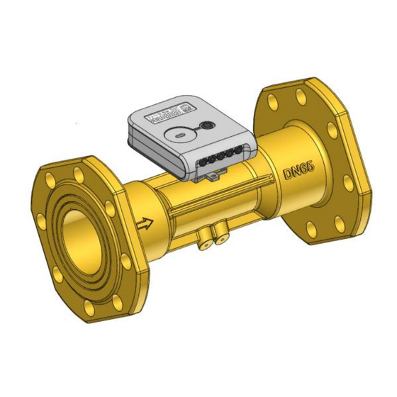
- Page 41 Annex B (continued) Fig. B2.8 Flow sensor q = 25 m /h; L=300 mm; connection type: flanges DN65 Fig. B2.9 Flow sensor q = 40 m /h; L=300 mm; connection type: flanges DN80 Fig. B2.10 Flow sensor q = 60 m /h;...
- Page 42 Annex B (continued) B3. Overall dimensions of temperature sensors Fig. B3.1 Overall dimensions of the DS type temperature sensor Fig. B3.2 Overall dimensions of the PL type temperature sensor Nominal pipe diameter, mm Total length of pocket L, mm DN20...DN100 DN125...DN150 DN200 a) Dimensions of the PL type temperature sensor protective pocket...
-
Page 43: Annex C
Annex C Fig. C1 The sealing diagram of calculator (at the back side of the box): It shall be sealed additionally only if the breakable partitions are damaged (1 – the supplier’s seal is attached after installation; 2 – verification seal stickers are attached – for version with permanently connected temperature sensors or supplier’s seal - for version with changeable temperature sensors) Flow sensor qp = 0.6/1.0/1.5/2.5 m b) Flow sensor qp = 3.5/6.0 m... -
Page 44: Manufacturer's Warranty
The warranty time is 12 months from the start of the operation but not later than 18 months from the day of manufacture. The address of the manufacturer: UAB “Axioma Metering”, Veterinaru str. 52, Biruliskes, LT-54469 Kaunas region, Lithuania tel. +370 37 360234; fax. +370 37 360358. PEE3V03 2019-12-03...
Need help?
Do you have a question about the QALCOSONIC E3 and is the answer not in the manual?
Questions and answers