Table of Contents
Advertisement
Quick Links
Advertisement
Table of Contents

Subscribe to Our Youtube Channel
Related Manuals for Grillo FK 700


Summary of Contents for Grillo FK 700
- Page 1 FK 700 Hydrostatic Mower OPERATOR’S MANUAL 02621.2024.06...
-
Page 2: Table Of Contents
FK 700 Hydrostatic Mower / Translation of the original instructions TABLE OF CONTENTS Introduction ................3 16. Troubleshooting guide ............26 Description and intended use ..........3 17. Maintenance schedule ............28 18. Lubrication chart ..............28 Safety decals ................4 General safety rules ............... 5 19. Storage and prolonged inactivity ........29 General warnings to keep in mind ........ -
Page 3: Introduction
INTRODUCTION Dear Customer, we thank you for the trust and preference you have placed in our Grillo FK 700 and we are confident that the use of your new machine will fully meet your requirements. For optimal use and maintenance over time, please carefully read and follow the instructions in this booklet; this will enable you to obtain the best results and safeguard your purchase. Please keep this manual, which should always accompany the machine as an integral part of it. Reading the operator’s manual is very important. DESCRIPTION AND INTENDED USE The Grillo FK 700 is a ride-on hydrostatic mower designed for shredding and cutting grass. -
Page 4: Safety Decals
SAFETY DECALS VIEW FROM THE DRIVING SEAT Consult the manual Danger of bursting Danger of burns Danger of fire Danger of injury Danger of gas caused by inhalation transmission parts Sound power level Danger of machine overturning LEFT-HAND SIDE OF THE FLAIL MOWER Danger of injury from sharp knives Risk of injury caused by the rotation of the cardan joint... -
Page 5: General Safety Rules
GENERAL SAFETY RULES Danger of injury caused by transmission parts ccident prevention rules On the machine and in this manual there are warnings and indications accompanied by this symbol: When the engine is running, never touch pulleys or belts, do not carry out maintenance and keep hands away from the designated area. Danger of machine overturning it indicates the presence of a potential hazard for which particular caution should be taken for your own safety and for the safety of others who may be within the operating range of the machine. Do not use the machine on slippery ground or on slopes with a gradient greater than 20° (36%). Danger of bursting All accident prevention rules in this manual are important and must be observed. Always keep the manual handy and read it carefully to learn... - Page 6 Lifting points Use the points indicated for lifting the flail mower. Danger of explosion Keep the battery away from flames or sparks. The gases that may escape are highly explosive. Danger from acid CAUTION: the roll-bar safety device must always be kept raised and tightened during work. Use the seat belt as well. The acid contained in the battery is highly toxic if inhaled. It can also cause skin burns, puncture clothing and cause blindness if in contact with the eyes. ersonal protection equipMent Before using the machine the appropriate personal protection equipment must be worn: body protection, protective gloves, safety footwear, hearing protection, goggles.
-
Page 7: General Warnings To Keep In Mind
If damaged, repair them before putting the flail mower back into operation; • If the machine begins to vibrate abnormally after a knock, immediately carry out a general check to identify the reason for the anomaly. If necessary, request the assistance of an authorised Grillo workshop; WARNING: Read carefully before operating the machine. • The rotation of the flail rotor is very dangerous, never put hands or feet under the rotor;... -
Page 8: Identification Of Use Decals
IDENTIFICATION OF USE DECALS FRONTAL VIEW OF THE MACHINE Reverse Machine grease points Neutral Hydraulic distributor Forward Parking brake Emergency Differential lock brake VIEW FROM THE DRIVING SEAT Throttle Gear selector RIGHT-HAND SIDE OF THE FLAIL MOWER Flail mower grease points... -
Page 9: Identification Of Machine Controls And Functions
IDENTIFICATION OF MACHINE CONTROLS AND FUNCTIONS 12 11 1. STEERING WHEEL 16. DRIVE LEVER 2. PTO BUTTON 17. BATTERY CUT-OFF SWITCH 3. ENGINE OIL WARNING LIGHT 18. AIR FILTER 4. BATTERY WARNING LIGHT 19. TRACTION BYPASS SCREW 5. ENGINE PREHEATING WARNING LIGHT 20. -
Page 10: Identification Of Flail Mower Components
IDENTIFICATION OF FLAIL MOWER COMPONENTS 1. CUTTING HEIGHT LOCKING LEVERS 9. KNIVES 2. HEIGHT-ADJUSTABLE WHEEL FORK 10. BELT TENSIONER IDLER 3. FLAIL BODY LOCKING SCREWS (X 5) 11. BELT TENSIONER SPRING 4. TRANSMISSION COVER 12. GEARBOX 5. LOWER SKID 13. CARDAN SHAFT COVER 6. -
Page 11: Technical Specifications
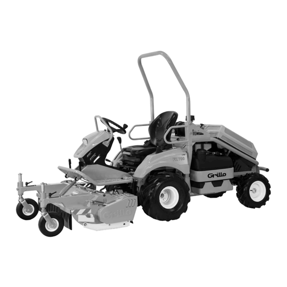
TECHNICAL SPECIFICATIONS Fig. 1 MODEL: FK700, hydrostatic mower with front flail mower. ENGINE: KUBOTA D722-E4B-EU-Y2, Diesel EPA/CARB Tier 4, EU Stage V, ECE R120, 722 cc, 13.2 kW (18 HP) at 3200 rpm, 3 cylinders, liquid cooled, with electric fan and automatic radiator cleaning device. FUEL TANK CAPACITY: 31 litres. HYDRAULIC OIL CIRCUIT CAPACITY: 6.5 litres. STARTER: electric 12 V. -
Page 12: Operating Instructions
OPERATING INSTRUCTIONS 10.3 STARTING THE MACHINE 1. Set the cutting height by adjusting the wheels on the flail mower (see 12.2 Cutting height adjustment); 10.1 CHECKS TO BE CARRIED OUT BEFORE 2. Adjust the seat and carry out the necessary checks as described STARTING THE ENGINE above; 3. Start the engine; Check that: 4. Release the parking brake by removing the lever from the housing •... -
Page 13: Work Conclusion
10.4 WORK CONCLUSION Fig. 6 Once finished mowing, disengage the PTO and empty the grass catcher. Then: 1. Bring the drive lever to the neutral position (fig. 2/N) to stop; 2. Set the throttle to minimum (fig. 5/MIN); 3. If the flail mower was raised, lower it to the ground; 4. Switch the engine off by turning the key to the stop position (fig. 3/0) and apply the parking brake, pulling the lever upwards and positioning it in the housing (fig. 4/ON); 5. Finish by cleaning the machine. 10.5 ORDINARY MACHINE CLEANING At the end of each job, proper cleaning ensures a long service life for the Fig. -
Page 14: Sloping Terrain And Differential
11.1 ELECTRONIC SAFETY wheels uphill do not encounter any obstacles (stones, branches, roots, etc.) that could cause the machine to lose control. If the drive wheels tend On the FK 700, an electronic control unit receives signals from the to slip, use the hydraulic control (fig. 8/UP) to lift the flail mower slightly in microswitches located on the seat, drive lever and parking brake (see order to put more weight on the drive wheels and thus have more traction. 15.6 Electrical system maintenance). Based on these signals, the control Consider the various situations and be careful on damp ground and wet unit generates logic blocks for the safety of the machine and the operator. -
Page 15: Ordinary Adjustments
ORDINARY ADJUSTMENTS CAUTION: in order to avoid serious injuries due to the machine overturning, keep the roll-bar raised and use the safety belt. In addition, make sure that the seat is securely fastened via the 12.1 SEAT ADJUSTMENT securing latch behind the seat (fig. 11/B). Before starting work, it is recommended to position the seat in the most CAUTION: only lower the roll-bar when absolutely necessary, comfortable position and with the most control over the machine. for short periods and raise it immediately as soon as conditions •... -
Page 16: Cutting Height Adjustment
12.2 CUTTING HEIGHT ADJUSTMENT The height of the flail mower is adjustable in 4 fixed positions. To adjust the cutting height: 1. Lift the flail mower with the hydraulic distributor lever (fig. 8/UP); 2. Switch off the engine; 3. Loosen the lever near the flail mower wheel (fig. 13/A); 4. Pull the lever towards the machine (fig. 13/B) and select one of the 4 vertical fork positions (fig. 13/C); 5. Pull the lever back towards the flail mower and tighten it again; 6. Repeat the operation for the other wheel, ensuring that both wheels are adjusted to the same height. In the event of uneven ground, dips or bumps, it is advisable to operate the flail mower in the highest cutting setting in order to avoid impact on the knives. -
Page 17: Extraordinary Adjustments
EXTRAORDINARY ADJUSTMENTS 13.3 ADJUSTING THE FLAIL MOWER BELTS To adjust the flail mower belt tension: CAUTION: the adjustment procedures described below require 1. Loosen the lock nut (fig. 17/A); technical skills and expertise. 2. Screw/unscrew the nut (fig. 17/B) so that the tip of the red tension It is advisable to contact an authorised Grillo centre to undertake indicator (fig. 17/C) is aligned with the edge of the spring. these procedures. Fig. 17 13.1 ADJUSTING THE PARKING BRAKE If the parking brake is ineffective, it is possible to adjust it using the adjuster located under the seat: by loosening the bolts (fig. 15/A) it is possible to increase or decrease the opening of the brake caliper by turning the angle of the plate that operates the mechanism (fig. 15/B). -
Page 18: Ordinary Maintenance And Lubrication
ORDINARY MAINTENANCE AND LUBRICATION Fig. 19 CAUTION: if the machine or part of it has to be lifted, always use suitable tools such as supports and safety locks. • Always wear appropriate clothing and work gloves before starting any cleaning, maintenance or repair work; • Do not leave the machine in service without safety devices or lifted, in places accessible to inexperienced persons, especially children; • Never dispose of waste oil, fuel or any other pollutant in the environment! •... -
Page 19: Battery Maintenance
Fig. 21 Fig. 23 ngine cooling systeM Fig. 22 In order not to impair the passage of air, check that the protective grille of the radiator is always clean. The radiator fan is driven by an electric motor; if the radiator grille becomes clogged and the temperature of the coolant rises above 95°C, the fan automatically reverses rotation for a few seconds to clean the grille. To inspect and clean the fan, open the rear bonnet by pulling the handle (fig. 20/A). To access the radiator, disengage the rubber catch and open the grille (fig. 20/B). -
Page 20: Flail Mower Maintenance
To inspect the cutting rotor, switch off the engine, engage the parking CAUTION: the operations contained in this chapter require brake and proceed as follows: technical skills and special equipment. 1. Slightly lift the flail mower with the hydraulic distributor lever (fig. 8/ It is advisable to contact an authorised Grillo centre. UP) in order to relieve its weight from the ground; 2. Manually lift the footplate and secure it with the latch (fig. 24/A); 15.1 FUEL SYSTEM MAINTENANCE 3. Loosen the 5 fixing screws (fig. 24/B); 4. Lower the flail mower with the hydraulic distributor lever (fig. 8/ FLOAT);... -
Page 21: Cooling System Maintenance
15.2 COOLING SYSTEM MAINTENANCE 15.3 HYDRAULIC SYSTEM MAINTENANCE The hydraulic lever distributor (fig. 8) operates at a maximum operating pressure of approximately 140 bar. It makes the flail mower floating or hanging the coolant can lift it. 1. With the engine switched off and cold, open the rear bonnet and Check the level in the hydraulic oil tank (fig. 29/A) periodically, when the open the radiator grille (fig. 20); oil is cold. To check the level or to top up the oil, unscrew the oil level cap. 2. Unscrew the radiator cap (fig. 28/A) and the screws underneath Check the level by using the dipstick (fig. 29/B) of the oil tank cap: the (fig. 28/B) in order to remove the old fluid completely; level must be between the two notches at the end of the dipstick. Check 3. Retighten the lower screws and pour the new fluid into the radiator the level by screwing the cap on and off completely each time. To remove until it is completely filled;... -
Page 22: Flail Mower Maintenance And Complete Disassembly
If any oil leaks are noticed, we recommend contacting the authorised CAUTION: before starting the machine, it is nevertheless Grillo service centre. good practice to ensure that the cardan shaft is properly connected on both the flail mower and the machine and the stop button is Fig. - Page 23 3. Tension the belts by bringing the spring to the correct compression Fig. 36 so that the tip of the red tension indicator is aligned with the end of the spring (see 13.3 Adjusting the flail mower belts). Fig. 34 eplacing the hydraulic puMp belt To replace the pump belt, proceed as follows: eplacing the belts 3. Unhook the spring of the idler pulley (fig. 37/A); For their replacement proceed as follows: 4. Manually lift the idler pulley (fig. 37/B); 1. Tip the seat and secure it in place with the support rod; 5. The belt can now be replaced. 2. Unscrew the two bolts securing the fuel tank (fig. 35/A) and pivot 6. Once the replacement is complete, re-attach the idler spring. The the fuel tank (fig. 35/B) to gain access to the clutch;...
-
Page 24: Electrical System Maintenance
15.6 ELECTRICAL SYSTEM MAINTENANCE elays Positioned behind the seat are: • 4 radiator fan control relays (fig. 39/B); uses • 4 engine power supply relays: ignition key, glow plugs, starter The electrical system is protected by fuses that, if interrupted, will cause motor, solenoid (fig. 39/C); the complete ineffectiveness of the whole electrical system. There are two • 1 power relay for the electromagnetic clutch (fig. 39/D). main 40 A fuses: one protects the entire electrical system (fig. 38/A) and the other protects the radiator fan (fig. 38/B). Behind the seat there are eutral position Microswitch other fuses to protect the components of the electrical system (fig. 39/A). The drive lever activates a microswitch (fig. 40/A) that signals the neutral If electrical problems persist after the fuses have been replaced, contact position of the machine. -
Page 25: Battery Replacement
15.8 WHEEL MAINTENANCE zeros (000000) appears. The count is automatically reset. Use only Tubeless 4-ply (4PR) tyres in sizes 20x10.50-8 for the front and 16x6.50-8 for the rear. perator presence Microswitch Routinely check the tyre pressure, which should be 1.5 bar (21 psi) for The operator presence microswitch is located under the seat and detects all four wheels. the presence of the operator when seated in the driver’s seat. Always ensure that the valve protection cap is in place. The purpose of the cap is to prevent foreign bodies from entering the valve, damaging it 15.7 BATTERY REPLACEMENT and causing pressure loss; always tighten the cap by hand. -
Page 26: Troubleshooting Guide
TROUBLESHOOTING GUIDE FK 700 - TROUBLESHOOTING GUIDE PROBLEM CAUSE SOLUTION - Check the battery cut-off switch The dashboard remains - Check the connection cables off, with the key in any - Check the electrolyte level in the battery The battery does not supply any current position besides the STOP - Recharge the battery position. - Page 27 FK 700 - TROUBLESHOOTING GUIDE PROBLEM CAUSE SOLUTION - Check the PTO button - Parking brake applied - Check the function and integrity of the clutch - Faulty switch - Check the fuses The PTO does not engage - Defective clutch - Check the operation and adjustment of the parking - Defective parking brake microswitch brake microswitch - High engine temperature...
-
Page 28: Maintenance Schedule
MAINTENANCE SCHEDULE FK 700 - MAINTENANCE SCHEDULE EVERY FIRST EVERY EVERY EVERY EVERY EVERY MAINTENANCE ITEM BEYOND 8 HOURS 20 HOURS 40 HOURS 50 HOURS 75 HOURS 100 HOURS 150 HOURS ● Check the level ● Engine oil ● Replace (FIRST CHANGE) ● ● Engine oil filter Replace (FIRST... -
Page 29: Storage And Prolonged Inactivity
To move the machine with the engine switched off, it is necessary to loosen the screw on the hydrostatic pump (fig. 44/A); use a 16 mm - 5/8” We advise the customer to note down this additional information in spanner. Loosen the screw by a maximum of two turns. the spaces below. It may be useful for the service department. CAUTION: in this way the effectiveness of the braking device PURCHASE DATE ..................is invalidated. GRILLO DEALER ..................IMPORTANT: tow the machine at very low speed and for short distances, 100 m maximum, to avoid damaging the hydraulic 21.3 SPARE PARTS pump and the motor. To restore correct operation of the machine, It is recommended to use only genuine spare parts, which are the only remember to tighten the screw again, with a maximum torque of 14 ones that provide safety and interchangeability. -
Page 30: Transport Warnings
TRANSPORT WARNINGS owing hitch This machine can be used for towing only occasionally and with certain limitations. The towing hitch is a service to be used occasionally and consciously, therefore the following limitations must be observed: • Weight of the towed mass (on wheels) less than 50% of the machine weight; • Non-continuous towing (max 300 m without stopping) on a plain or light slope (max 10%). IMPORTANT: use beyond the limits may impair or cause serious damage to the hydrostatic transmission. ifting and transport If the machine is to be transported on a truck or trailer, lower the flail mower, apply the parking brake and secure it to the means of transport using ropes, cables or chains at the points indicated by the arrow (fig. 46). -
Page 31: Declaration Of Conformity
GRILLO SPA – Via Cervese, 1701 – 47521 CESENA (FC) – ITALY declare that the following machinery: / dichiaro che la macchina di seguito indicata: / déclare que la machine suivante: / Hiermit erkläre ich, dass folgende Maschine: / declara que la siguiente máquina:... - Page 32 Tel: (+ 44) 01889569149 Website: www.grillospa.it Website: www.grilloagrigarden.co.uk E-mail: grillo@grillospa.it E-mail: info@grilloagrigarden.co.uk Grillo Australasia Pty Ltd Grillo Deutschland GmbH 14 REBECCA COURT - VIC 3943 SORRENTO - AUSTRALIA GUNTERSRIETHER STR.14 - 91224 HARTMANNSHOF - DEUTSCHLAND Tel: (+ 61) 0428206225 Tel: (+ 49) 09154949216 Website: www.grilloaustralia.com.au...
Need help?
Do you have a question about the FK 700 and is the answer not in the manual?
Questions and answers