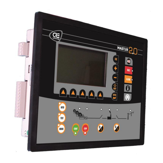
CRE Technology MASTER 2.0 Application Note
For tie breaker synchronization
Hide thumbs
Also See for MASTER 2.0:
- Technical documentation manual (182 pages) ,
- Technical documentation manual (244 pages)
Table of Contents
Advertisement
Quick Links
MASTER
2.0
Application Note
"MASTER 2.0 for Tie breaker synchronization"
Reference:
A54 Z0 2 0002 C EN
CRE Technology believes that all information provided herein is correct and reliable and reserves the right
to update at any time. CRE Technology does not assume any responsibility for its use. E & O E.
Advertisement
Table of Contents

Summary of Contents for CRE Technology MASTER 2.0
- Page 1 A54 Z0 2 0002 C EN CRE Technology believes that all information provided herein is correct and reliable and reserves the right to update at any time. CRE Technology does not assume any responsibility for its use. E & O E.
- Page 2 For further information, please contact your CRE Technology distributor or the After-Sales Service Team. All CRE Technology products are delivered with one year warranty, and if necessary we will be happy to come on site for product commissioning or troubleshooting. The company also provide specific trainings on our products and software.
-
Page 3: Table Of Contents
OVERVIEW................................4 CONFIGURATION ..............................5 ........................5 VERVIEW AND AN BUS INHIBITION MASTER 2.0 ........................... 6 SETTINGS ........................6 ONTROL COMMAND SEQUENCE IMPORTANT RECOMMENDATIONS ........................8 COMPLEX EXAMPLE............................9 CRE TECHNOLOGY ............................11 A54 Z0 2 0002 C EN... -
Page 4: Overview
Bus bar 1 = BB 1= bus bar on left side, plugged in Gen side of MASTER 2.0 unit (B1,B2,B3). Bus bar 2 = BB 2 = bus bar on right side, plugged in Mains side of MASTER 2.0 unit (B4,B5,B6). -
Page 5: Configuration
When Tie breaker is open, DG1 and DG2 must communicate together (for load sharing) and ignore the DG3 (and vice versa). The MASTER 2.0 is permanently inhibited by GENSYS2.0 placed on his right, but not by left side GENSYS2.0, which are possibly synchronized. -
Page 6: Master 2.0 Settings
E2514), control by PLC. The MASTER 2.0 is placed in Manu Mode regardless the state of the Tie breaker. He must be placed in Auto Mode only when the synchronization is requested, and set in Manu as soon as he closed the Tie breaker. - Page 7 Control sequence : Figure 2 – Control sequence Note: The variable E2946 allows you to change modes of operation (E2946 = 1 for Auto mode; E2946 = 3 for Manu mode). There are also functions of forcing entry logical or variable (E2260 = forcing Mode Auto;...
-
Page 8: Important Recommendations
All protections (Mains and Gen) must be inactivated ("not used") in MASER2.0 device. MASTER 2.0 is only used to synchronize the 2 bus bar. He does not control the power, ramp, load sharing… (Load sharing will be control by the GENSYS2.0 once coupled). -
Page 9: Complex Example
4 Complex example Synoptique A54 Z0 2 0002 C EN... - Page 10 Inhibitions table A54 Z0 2 0002 C EN...
-
Page 11: Cre Technology
Agents Figure 2 – CRE Technology distributors CRE Technology retains all copyrights in any text, graphic images, and software owned by CRE Technology and hereby authorizes you to electronically copy documents published herein solely for the purpose of transmitting or viewing the information.


Need help?
Do you have a question about the MASTER 2.0 and is the answer not in the manual?
Questions and answers