Table of Contents
Advertisement
Quick Links
CRE technology believes that all information provided herein is correct and reliable and reserves the right to update at
any time. CRE Technology does not assume any responsibility for its use unless otherwise expressly undertaken.
Allée Charles-Victor Naudin - Zone des Templiers - Sophia Antipolis
Unigen Plus & Industrial Unigen - User technical documentation
A51Z090004-D
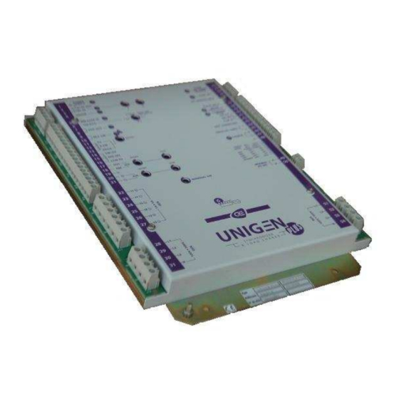
Synchronization and load sharing module
Technical documentation
Téléphone : + 33 (0)4.92.38.86.82 - Fax : + 33 (0)4.92.38.86.83
Internet:
November 2006
A51Z090004-D.doc
CRE technology
06410 BIOT - FRANCE
http://www.cretechnology.com
page 1/19
Advertisement
Table of Contents

Related Manuals for CRE Technology Unigen Plus


Summary of Contents for CRE Technology Unigen Plus
- Page 1 Synchronization and load sharing module Technical documentation CRE technology believes that all information provided herein is correct and reliable and reserves the right to update at any time. CRE Technology does not assume any responsibility for its use unless otherwise expressly undertaken.
-
Page 2: History
Version B: September 2005 : modification of the picture of the cover (P4). • Version C: October 2006 : adaptation of the document for new hardware of the Unigen for Unigen Plus A51M109 and Industrial Unigen. • Version D: November 2006 : addition of the Modbus, Command mode and Mains paralleled functions. -
Page 3: Table Of Contents
Features ...................................5 2.1. Synch check relay..............................5 2.2. Reverse kW relay ..............................5 2.3. Remote speed control input ............................5 2.4. Isochronous load sharing (for Unigen plus) with PARALLELING LINES.............6 2.5. CAN load sharing..............................6 2.5.1. Plug and play..............................6 2.5.2. Automatic load/unload request.........................6 2.6. -
Page 4: Overview
• Internal synch check relays, useful for auto and manual synchronization. • Phase sequence protection. • Load sharing with CAN plug and play (‘sw1’ configuration) or with paralleling lines(for Unigen Plus: ‘sw3’ configuration). • Automatic load/unload. • Reverse Kw relays. -
Page 5: Features
This input can also be used as 0-5Vdc for a master PLC control. In this case the nominal speed have to be adjusted with 2.5 VDC applied on cursor input. Unigen Plus & Industrial Unigen - User technical documentation A51Z090004-D... -
Page 6: Isochronous Load Sharing (For Unigen Plus) With Paralleling Lines
2.5. CAN load sharing. When ‘DROOP’ (terminal 4) input is opened and the switch ‘sw3’ (plines/canbus) is on canbus (ON position) (for Unigen Plus), UNIGEN is in isochronous load sharing mode. The load setpoint will be calculated via the CAN connection. -
Page 7: Load Sharing
‘UNLOAD’ (terminal 6) input disconnected = when the breaker closes, the load ramp starts immediately. • ‘UNLOAD’ (terminal 6) input connected to 0v = the generator starts an unload ramp. Unigen Plus & Industrial Unigen - User technical documentation A51Z090004-D page 7/19... -
Page 8: Droop Load Sharing
4->and the generator breaker is closed (terminal 5 connected to the 0VDC), then the UNIGEN Plus is in ‘Mains paralleled’ mode. The setpoint load is fixed by the paralleling lines (terminals 44/45) (coming from the GCR for example) and the power factor is fixed at 0.95 by the parameter ‘E11020’. - Page 9 Close: connected to the 0VDC. Open: not connected. Unigen Plus & Industrial Unigen - User technical documentation A51Z090004-D page 9/19...
-
Page 10: Modbus(For Unigen Plus)
2.10. Modbus(for Unigen Plus ) Put the ‘sw8’ (Modbus OFF/120 ) on ON position (resistor of 120 ) when the Unigen Plus is used on end of line. All the logical and analogue input/output values and all the other parameters which appear in the UNIGEN Plus menus can be obtained by the serial port RS485 terminals 49A and 50B (2 wires). -
Page 11: Settings
‘SYNC OK’ (terminals 34/35) closes on deadbus condition. sw7‘OFF/ON’ is not used. sw8‘terminal resistor of Modbus’: OFF position resistor not connected; ON position resistor of 120 connected. Not used switch for Industrial Unigen. Unigen Plus & Industrial Unigen - User technical documentation A51Z090004-D page 11/19... -
Page 12: Display
Green LED. COMMAND This LED is ON when a command mode is required (input MODE ‘COMMAND MODE’ closed to the 0Vdc) (for Unigen Plus). Green LED. This LED is flickering when the load sharing mode is the canbus. CANBUS This LED flickers according to the number of Unigen communicating in the canbus (‘sw3’... -
Page 13: Terminals
The nominal current of the secondary of the current Generator I2 - 2.5 / 13 transformers must be as close as possible to 5Amps. Generator I3 + 2.5 / 13 Generator I3 - 2.5 / 13 Unigen Plus & Industrial Unigen - User technical documentation A51Z090004-D page 13/19... - Page 14 Note: Cable sizes are for guidance only. Cable size should be increased for long cable runs, to overcome possible voltage drop and to increase noise immunity. Only for Unigen Plus. Unigen Plus & Industrial Unigen - User technical documentation A51Z090004-D page 14/19...
-
Page 15: Wiring Diagram
5.2. Wiring diagram Each terminals of the industrial Unigen are on the Unigen Plus. Auto Mains Failure Breaker control Rev. kW Modbus A Trip out Modbus B breaker IN CAN+ UNIGEN Gen I1+ CAN- Gen I1- Gen I2+ Parallel lines high... -
Page 16: Commissioning
The grounding must be done in a proper way to avoid personal injuries and for a reduction of EMC. 6.1.3. Vibrations: In case of heavy vibrations, the UNIGEN should be mounted using AV Mounts. Unigen Plus & Industrial Unigen - User technical documentation A51Z090004-D page 16/19... -
Page 17: Power Plant Start-Up/Commissionning
Close the ‘SYNC IN’ input (terminal 3 to 0 Volts). UNIGEN is trying to synchronize on a dead bus (00.00Hz). • Adjust the speed gain RV10 to have 48,00Hz. • Open the ‘SYNC IN’ input. Unigen Plus & Industrial Unigen - User technical documentation A51Z090004-D page 17/19... - Page 18 If the test is OK, connect the wires of the relay ‘SYNC OK’ (terminals 34/35) of the Unigen. Load sharing / kW regulation • Regarding the application check the stability of KW and kVAR regulation. • Stop engines. Unigen Plus & Industrial Unigen - User technical documentation A51Z090004-D page 18/19...
-
Page 19: Environment
Directive CE: Generic emission standard: EN 50081-2, EN 50082-2. Generic immunity standard: EN 61000-6-2. Low voltage directive: 73/23EEC. 8. Dimensions 165mm 115mm 25mm Holes D=5mm 200mm nut 5 grounding Unigen Plus & Industrial Unigen - User technical documentation A51Z090004-D page 19/19...
Need help?
Do you have a question about the Unigen Plus and is the answer not in the manual?
Questions and answers