CRE Technology GENSYS 2.0 Technical Documentation Manual
Generator management module
Hide thumbs
Also See for GENSYS 2.0:
- Technical documentation manual (244 pages) ,
- Application note (11 pages)
Table of Contents
Advertisement
Quick Links
GENSYS 2.0
Generator management module
Technical Documentation
CRE Technology believes that all information provided herein is correct and reliable and reserves the right to update at
any time. CRE Technology does not assume any responsibility for its use. E & O E.
CRE Technology
130 Allée Charles-Victor Naudin
Zone des Templiers - Sophia Antipolis
06410 BIOT - FRANCE
Phone: + 33 (0)4.92.38.86.82 - Fax: + 33 (0)4.92.38.86.83
www.cretechnology.com - info@cretechnology.com
SARL au Capital de 300.000 Euros - RCS Antibes: 7488 625 000 15 N°TVA FR54 488 625 583
A53 Z0 9 0020 I En - Technical documentation.doc
1/182
Advertisement
Table of Contents

Related Manuals for CRE Technology GENSYS 2.0


Summary of Contents for CRE Technology GENSYS 2.0
- Page 1 Generator management module Technical Documentation CRE Technology believes that all information provided herein is correct and reliable and reserves the right to update at any time. CRE Technology does not assume any responsibility for its use. E & O E.
- Page 2 July 21 2009 Removal of USB connection. Addition of Ethernet connection. Firmware update using SD card added. Chapter on GENSYS 1.0/GENSYS 2.0 compatibility added. Extra information concerning analogue sensors. Sept 25 2009 Information concerning CEM compliance added. Ethernet connection added and USB connection chapter updated.
- Page 3 A53 Z0 9 0014 x-EN is the GENSYS 2.0 Menu reference manual: this is a Windows help file (.chm). This file contains all references to the man-machine interface (local and html pc web site). This documentation is generally used as reference during the installation phase.
-
Page 4: Table Of Contents
Single generator in change-over mode ....................36 Single generator in no-change-over mode ..................38 Generators paralleling with digital bus ....................39 Generators paralleling with GENSYS 2.0 and parallel line modules............. 40 Multiple generators with static paralleling ..................41 Single generator paralleled with mains ....................43 Power plant paralleled with mains using MASTER 2.0 or GCR ............ - Page 5 Operator controlled return to mains ....................84 11.3 Mains & Generator electrical fault options..................85 11.4 Generator electrical fault ....................... 87 11.5 GENSYS 2.0 with external automatic start module ................. 88 11.6 Remote start upon external pulse ....................89 11.7 Safety Inhibitions ........................... 90 11.8 Use of BSM II with GENSYS 2.0 .......................
- Page 6 15.7 Dedicated screens........................173 Useful Information ........................ 176 Variables ..........................178 Precautions..........................179 References ..........................181 19.1 Options ............................181 19.2 Accessories ..........................181 Company Information ......................182 A53 Z0 9 0020 I En - Technical documentation.doc 6/182...
- Page 7 Figure 45 - Permanent mains paralleling with one input as "Mains electrical fault" ............87 Figure 46 - Permanent mains paralleling and generator electrical fault ................87 Figure 47 - Wiring GENSYS 2.0 Auto Start Module ...................... 88 Figure 48 – Wiring GENSYS 2.0 to BSM II ......................... 92 Figure 49 - Wiring GENSYS 2.0 ...
- Page 8 Figure 65 - CAN Bus wiring............................123 Figure 66 - GENSYS 2.0 GENSYS 2.0 .......................... 123 Figure 67 - GENSYS 2.0 GENSYS 2.0 GENSYS 2.0 … ..................124 Figure 68 - Mobile generator sets ..........................124 Figure 69 - Connecting J6 to broadcast variables ......................
- Page 9 Table 35 – DB9 pin out ..............................122 Table 36 - Broadcast variables sent over inter GENSYS 2.0 CAN bus................126 Table 37 – Broadcast variables received by BROADCAST DATA from inter GENSYS 2.0 CAN bus ........127 Table 38 - CAN bus inhibition variables ......................... 130 Table 39 - CAN bus inhibition parameters ........................
-
Page 10: Overview
1 Overview 1.1 European Union Directive Compliance CE The EMC Directive (89/336/EEC) deals with electromagnetic emissions and immunity. This product is tested by applying the standards, in whole or in part, which are documented in the following technical construction file: CEM 2004/108/EC, which replaces directive CEM (89/336/EEC) relative to electromagnetic emissions as from July 20th 2009. -
Page 11: Description
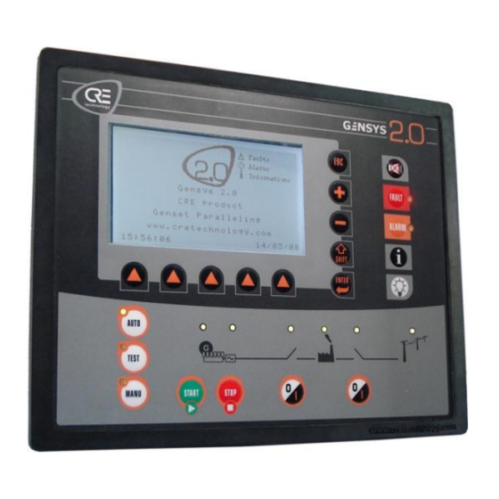
Table 1 - GENSYS 2.0 Front Panel The display panel allows setting up and monitoring of the GENSYS 2.0 configuration and the power plant it controls. It provides a large LCD display and a keypad. See "User interface" chapter, page 22, for more details about the functions of LEDs &... -
Page 12: Table 3 - Display Panel Keys
2.1.1 Display panel The five dedicated keys of the display panel allow direct access to special menus or functions. See "User interface" chapter, page 22, for more details about the functions of LEDs & Keys. Table 3 - Display Panel keys Input mode Navigation mode (during parameter modification) - Page 13 Pressing a second time on the same key will switch back to the menu displayed beforehand. Bulb LED test: pressing this key will turn on all GENSYS 2.0 LEDs. It is a simple test to check the LEDs and the keypad.
-
Page 14: Table 4 - Control Panel Keys
2.1.3 Control panel The control panel allows the user to pilot and control the generator. See "User interface" chapter, page 22, for more details about the functions of LEDs & Keys. Function upper This LED is illuminated when a key is pressed and is switched off when all keys are right released. -
Page 15: Table 5 - Control Panel Leds
2.1.4 Control panel LEDs Function Engine Green LED lit when engine is running. Alternator Green LED lit when generator voltage is present. Genset Green LED lit when generator breaker is closed. breaker Mains Green LED lit when mains breaker is closed. breaker Mains / Bus voltage... -
Page 16: Rear Panel - Connectors
2.2 Rear panel - Connectors 2.2.1 Overview Figure 2 - Rear panel A53 Z0 9 0020 I En - Technical documentation.doc 16/182... - Page 17 , 5A max. Details in §8.4.2 To battery positive, normally closed; direct supply to crank and Emergency stop 2.5 / 12 fuel relay outputs. Not necessarily connected: if not connected, GENSYS 2.0 will Generator N 2.5 / 12 calculate a virtual neutral voltage. Generator L1 2.5 / 12...
- Page 18 Terminal capacity Terminal Description Comment (mm² / AWG) 2.5 / 12 Engine meas. 1- (shielded) 0 to 10kΩ resistive sensors with programmable gain. Details in §9.3 2.5 / 12 Engine meas. 1+ (shielded) 2.5 / 12 Engine meas. 2- (shielded) 0 to 10kΩ...
- Page 19 Terminal capacity Terminal Description Comment (mm² / AWG) Digital input with 10kΩ pull-up. Dedicated input for mains breaker feedback. Mains breaker in 2.5 / 12 Accepts NO or NC contact to 0V. Not isolated. Digital input with 10kΩ pull-up. Dedicated input for generator breaker feedback. Gen breaker in 2.5 / 12 Accepts NO or NC contact to 0V.
-
Page 20: Figure 3 - Com1 Pin Out
PIN 8 PIN 9 Figure 4 - COM2 pin out GENSYS 2.0 with firmware v2.00 (or later) : This port is replaced by Ethernet communication. GENSYS 2.0 with firmware v1.xx : Type B standard USB connector. Use a standard USB A to B cable... -
Page 21: Figure 5 - Com4 Pin Out
Terminal capacity Terminal Description Comment (mm² / AWG) Standard RJ45 ETHERNET connector. Isolated. Uses TCP/IP protocol to communicate with external world. Details in §13.5 PIN 1 TX pair PIN 2 TX pair PIN 3 RX pair PIN 4 COM4 Ethernet RJ45 CAT5 PIN 5 PIN 6... -
Page 22: User Interface
In both cases, accessed menus are the same. Only the user interface changes (Front panel or PC). On power up, GENSYS 2.0 displays a WELCOME SCREEN during a short time, then switches to genset status (if EMERGENCY STOP is not connected): Figure 8 –... -
Page 23: Figure 9 - Password Input Mode Display
3.1.1 Security levels and passwords To manage menu access, the GENSYS 2.0 has different security levels which are password protected. These levels are explained in the next table. Different levels of authorization exist in the GENSYS 2.0 as described below:... -
Page 24: Local Navigation
Figure 10 - Main menu A full description of all MENU levels and items is given in chapter 15 3.2 Local navigation The 5 icons above the contextual keys will change in appearance depending on the type of parameter to modify (chosen list, label, numerical value, password...). -
Page 25: Remote Control Using A Pc (Ethernet Connection)
3.2.2 Saving actual configuration GENSYS 2.0 parameters used in configuration are stored in a FLASH memory. When a parameter is changed by the user, the new value is stored in a RAM memory. The new value will be effective as soon as it is entered, but it will be lost if power supply is lost. - Page 26 Click on « Settings ». Select « Ethernet (TCP/IP) ». Properties. A53 Z0 9 0020 I En - Technical documentation.doc 26/182...
- Page 27 Enter the addresses as shown above. Note: IP address 192.168.11.100 shown above can be used if GENSYS 2.0 IP address is 192.168.11.1 (factory setting). Otherwise, computer and GENSYS 2.0 IP addresses should match the same subnet mask as shown below.
- Page 28 Notes on Ethernet connection If you change the IP address of a GENSYS 2.0, you should also adapt Windows hosts file to be able to use the hostname (http://gensys/ or any other hostname of your choice) in your Web browser. Otherwise you will have to directly type the IP address of the GENSYS 2.0 you want to connect to in your Web browser.
-
Page 29: Figure 13 - Typical Menu
In this page, the user can choose from among 6 submenus (Genset electrical meters for example). It is also possible to scroll through the other pages of the menu with the << and >> links. The ESC link acts in the same way as the GENSYS 2.0 ESC key: it will display the parent menu. -
Page 30: Figure 14 - Typical Configuration Page
Figure 14 – Typical configuration page 3.3.4 Downloading a text file When you are connected with a computer, a text file can be transferred between the GENSYS 2.0 and the PC. This allows the following actions: Upload new parameters to the GENSYS 2.0. -
Page 31: Operating Modes
LED indicates that a voltage other than zero is measured. If a speed governor is connected to GENSYS 2.0, it is possible to increase the speed with the [+] key, and decrease it with the [-] key. -
Page 32: Test Mode
This mode allows testing automatic mode behaviour. When [Test] key is pressed, the engine starts as if there was a remote start, and GENSYS 2.0 will carry out the standard Auto mode sequence. To exit “TEST MODE”, push [AUTO] or [MAN] key. -
Page 33: Assisted Manual Mode
1/ When the generating set is running, the Open/Close generating set breaker button will switch the generating set on load. Depending on its setup (island mode, paralleled with Mains or other generating sets…), GENSYS 2.0 will automatically use the appropriate process: synchronization (if bus bar is live), closing the generating set’s breaker, loading ramp (if bus bar is live). - Page 34 2 / When paralleled with the Mains, pressing the Open/Close breaker buttons will open the appropriate breaker and let the generating set running until STOP button is pressed. (No break change over mode) Genset Load Mains Generating Waiting On load set ready Mains Immediate stop...
-
Page 35: Start Sequence
5 Start sequence During the start sequence protections are inhibited. This concerns all engine protections. When the engine reaches the required state (E2057 = 6, see next figure) the protections are activated. A timer can be added to inhibit protections during the "safety on"... -
Page 36: Predefined Configurations
6 Predefined configurations 6.1 Single generator in change-over mode Figure 16 - Power plant in change-over mode without paralleling Variable Related Menu Variable label Variable value number 1179 Gen. number Configuration/power plant overview 1147 Nb. of gen. Configuration/power plant overview 4006 Nb. -
Page 37: Table 9 - Typical Sequence In Change Over Mode
For the generator to start when mains failure occurs, either a protection (mains or other) or a digital input has to be configured as a "Mains electrical fault". If remote start is on when mains are present the generator starts, GENSYS 2.0 opens the mains breaker, then closes the generator breaker and takes the load. -
Page 38: Single Generator In No-Change-Over Mode
Configuration/power plant overview/>> Table 10- Typical no change over basic configuration In "No change over" mode (1148) GENSYS 2.0 only starts on receiving a remote start signal and doesn't manage the mains breaker. A53 Z0 9 0020 I En - Technical documentation.doc... -
Page 39: Generators Paralleling With Digital Bus
Table 11 - Typical basic multi Generator configuration In this mode, CAN bus on COM1 “inter GENSYS 2.0" is used to manage the different units on the same bus. This mode has better reliability and accuracy than equivalent analogue solutions. -
Page 40: Generators Paralleling With Gensys 2.0 And Parallel Line Modules
Table 13 - Typical basic configuration for GENSYS 2.0 with parallel line modules When GENSYS 2.0 is in ILS compatible mode, the active power sharing is handled via the parallel lines. You have to disconnect the AVR output (H2-H4) and have an external device control the reactive power (CT droop...). This mode is only recommended for use if you have older devices (which are not compatible with CAN inter GENSYS 2.0), with ILS... -
Page 41: Multiple Generators With Static Paralleling
6.5 Multiple generators with static paralleling This mode is useful when you urgently need to start a full plant with multiple generators. The generators will be ready to take load in the shortest possible time. This mode is also very useful when your installation includes high voltage transformers. Starting generators which are paralleled together gives a progressive magnetisation without peaks (no transient short-circuit). - Page 42 -One GENSYS 2.0 per generating set. -CAN bus must be connected between GENSYS 2.0 units. -An "Excitation" output (e.g. exit C1) must be configured on each GENSYS 2.0 unit. -Generator breaker must be powered by 24VDC (so as to close without AC).
-
Page 43: Single Generator Paralleled With Mains
6.6 Single generator paralleled with mains This function needs OPTION 2 to be installed. Configuration: Figure 21 - Paralleling with mains In permanent mode (1148) and peak shaving mode (1153), a mains power measurement is required. Internal via L1-L6 inputs (Mains I1, I2, I3), or external via G1-G3 inputs (0-20mA). Variable number Variable label Variable value... -
Page 44: Figure 22 - Typical Sequence In No Break Co Mode
When remote start is on, the generator starts, synchronizes and parallels with the mains, then takes the load (ramps up). Once the mains are unloaded, GENSYS 2.0 opens the mains breaker. When remote start is off, the mains takes the load in the same way as the generator did previously. -
Page 45: Figure 23 - Typical Sequence In Permanent Mode
Permanent mode When the remote start is on, GENSYS 2.0 starts the generator, synchronizes and parallels with the mains, then ramps up load until it reaches its set point. In base load mode (E1153), the generator has a constant load and the mains take the utility load variations. -
Page 46: Power Plant Paralleled With Mains Using Master 2.0 Or Gcr
MASTER 2.0 gives a maximum of 13 generators. Mains paralleling mode is fixed to « No changeover » when a single GENSYS 2.0 is used together with one or more MASTER 2.0. To allow Power Factor regulation, the "Mains breaker in" (J1) input to GENSYS 2.0 must be connected. Power Factor regulation is not an option. -
Page 47: Figure 25 - Gcr Gensys 2.0 Wiring Diagram
6.7.1 Interfacing GENSYS 2.0 with GCR Figure 25 - GCR GENSYS 2.0 wiring diagram GCR (39-40) – GENSYS 2.0 (G4-G6): parallel lines (0-3V) to control active power. GCR (42-43) – GENSYS 2.0 (G1-G3): mains synchronization bus (+/- 3V). GENSYS 2.0 (K3): -V from speed governor. -
Page 48: Power Plant Paralleled With Several Mains Using Master 2.0 Or Gcr
6.8 Power plant paralleled with several mains using MASTER 2.0 or GCR Figure 26 - Power plant paralleling with several mains This application requires additional modules to manage the mains power supply. Additional modules can be MASTER 2.0 (recommended) or GCR (not recommended for a new installation). MASTER 2.0 uses all-digital technology whereas GCR uses analogue load share lines (sometimes called Parallel Lines). -
Page 49: Installing And Commissioning A Gensys 2.0 Application
7 Installing and commissioning a GENSYS 2.0 application 7.1 Minimum wiring diagram A53 Z0 9 0020 I En - Technical documentation.doc 49/182... -
Page 50: Complete Wiring Diagram
7.2 Complete wiring diagram A53 Z0 9 0020 I En - Technical documentation.doc 50/182... -
Page 51: Figure 28 - Mounting Kit
-In accordance with the Bureau VERITAS marine agreement, the module must not be installed in areas which are exposed to the weather. 7.2.2 Mounting: To secure the GENSYS 2.0 onto the panel, use the special kit provided with the module. The kit contains 4 screws, 2 brackets and 1 mounting tool. Figure 28 - Mounting kit Remove the connectors. -
Page 52: Before Commissioning (Before Going On Site)
To avoid EMI, shield communication and ground cables appropriately. If several GENSYS 2.0 units are used, each of the 0V power supplies (pin K3) must be connected to each other with a 4mm² cable (use an adapter for the 2.5mm² connection to the GENSYS 2.0 power connector itself). -
Page 53: During Commissioning
Why? -To evaluate if an input/output needs an extra equation. -To evaluate quote / development time. -To evaluate necessary password clearance: Level 1 (consumer), Level 2 (Distributor), or Level 3 (CRE Technology only). 7.4 During commissioning Start with safe conditions How? Disconnect the GENSYS 2.0 connector labelled as “E”... - Page 54 Press the generator breaker [0/I] key. Check the breaker settings (§8.4.1) The breaker should close (control OK) and the GENSYS 2.0 front face led should light up (feedback position OK). Press the generator breaker [0/I] Key. The breaker should open and the led should go out.
- Page 55 “Active Power Regulation” menu. At the end of the ramp time, the GENSYS 2.0 will swap to “Kw Sharing Gain”. You can now set your load sharing gain and check the settings which depend on load impact (test with load bench, for example).
-
Page 56: Dedicated I/O Lines
The Speed ref (G11) doesn't need to be connected if there is no voltage reference available. 0V must be wired with 4 mm² cable as follows: battery speed governor GENSYS 2.0. See table below for presets. For specific settings contact your dealer. -
Page 57: Table 17 - Speed Governor Parameters
Terminal G9 Terminal Manufacturer Model Amplitude offset Remark (out) G11 (ref) (1076) (1077) 10 (Barber ECM pour QSK23 / Colman QSK40 / QSK45 / 1.00% 00.00% 06 (5Volts) Frequency QSX15 / QSK 60 CUMMINS bias input) Cf. Fig 34 ECM (QST30) 1.00% -3.00% 15(7,75v) -
Page 58: Figure 33 - Connexion Avec Un Efc Cummins
Because of the very high sensitivity of Cummins EFC module input, please use the schematic below to connect your GENSYS 2.0 to the EFC. This way, GENSYS 2.0 analogue speed output can be set higher (parameter E1076) according to the resistors used. -
Page 59: Speed And Voltage Control With Contacts / Pulses
Configuration/Transistor digital outputs 8.2.2 Calibration procedure Here follows the procedure for calibrating the +Hz and –Hz outputs on the GENSYS 2.0, necessary in order to have good frequency droop compensation and load sharing. -Show the following parameter on the information screen: E2058. - Page 60 -Start the engine using the GENSYS 2.0 in manual mode. -Engine should run near its nominal speed with deviation caused by mechanical droop. -Put engine in Automatic mode. If a difference in speed is measured, GENSYS 2.0 should vary the output until the engine is running at nominal speed.
-
Page 61: Analogue Avr (Auto Voltage Regulator) Control
Set to 0.1 sec which is the pulse length for frequency/voltage compensation. This parameter was adjusted for speed control, so do not modify. E2058 Load sharing / Synchro pulses only GENSYS 2.0 wants the genset to go faster Maxi(+Hz) = +7000 E1598 = DEADBAND Maxi( –Hz) = -7000 GENSYS 2.0 wants the genset to go slower... -
Page 62: Figure 36 - Voltage Output
If necessary, modify Gain and then Offset to obtain 430VAC ±5. Enter minimum correction (E2038 = - 7000) with Shift and “-” buttons, then check that you have 370VAC ±5 Set to no correction (E2038 = 0) and check that you have 400VAC. Gain and Offset adjustment if you cannot obtain 400V on the AVR: Adjust the maximum voltage with the AVR potentiometer, which is normally below 400VAC. -
Page 63: Table 19 - Avr Parameters
See table below for preset settings. For specific setting contact your dealer. AVR gain AVR offset Terminal Manufacturer Model Terminal H4 Remark (1103) (1104) MX321 A2 (+) A1 (-) Trim pot of AVR fully CW STAMFORD SX440 A2 (+) A1 (-) Trim pot of AVR fully CW AEC63-7 AVC63-4... -
Page 64: Relay Outputs
1 will mean “close the breaker” while a 0 will mean “open the breaker”. Breaker feedback is displayed on associated GENSYS 2.0 front panel LED (lit when breaker is closed) and variables E2000/ E2001 (1 when breaker is closed). -
Page 65: Table 20 - Breaker Control Configuration
E1992 (MAINS) Relay output Chronogram mode E1993 (GENSET) Continuous contact to open E1 (Mains) / E4 (Genset) Positive pulse to close E2 (Mains) / E5 (Genset) CLOSED OPEN Continuous contact to open E1 (Mains) / E4 (Genset) (default setting) Continuous contact (Contactor) to close E2 (Mains) / E5 (Genset) -
Page 66: Crank / Fuel / Starter 2 / Starter 3 Functions
Bobine à Manque E1994 Output Close Breaker Feedback E1995 Close Close Open WARNING: Never switch from one mode to another when the plant is in use. An unwanted breaker state modification may occur. To close the generator breaker the following conditions have to be met: Voltage must be between 70% (parameter E1432) and 130% (parameter E1433) of the nominal voltage (parameter E1107 or E1108). -
Page 67: Water Preheat / Pre-Lubrication / Pre-Glow Functions
Preheat is active when J7 is closed. The water temperature sensor isn’t required. Pre lubrication is active when J8 is closed. The oil pressure sensor isn’t required. Pre glow is active when J9 is closed, when you push GENSYS 2.0 start button, or if J10 is closed. 8.6.2 Automatic mode Pre-heat is activated if J6 is closed and if temperature is under the pre-set threshold (E0030 <... -
Page 68: Air Fan
8.7 Air fan GENSYS 2.0 J5: water temp input Output 1: C1 Air fan relay F6 / F7 Water temperature Output 1 function (1260) = Air fan (2215) sensor Figure 38 - Connection for air fans In all cases, the AIR FAN will be activated if J5 is activated or if the “max water temp” protection (F6/F7 analogue input) is configured and triggers. -
Page 69: Analogue Load Sharing Lines
Don’t forget to configure the output 1 in “Used by equations”. 8.9 Analogue load sharing lines It is possible to use traditional analogue load sharing lines (often called Parallel lines) with the GENSYS 2.0 product. The example shown is in association with a BARBER COLMAN product. -
Page 70: Watchdog Output
A watchdog option is available using the C5 output. This option must be specified upon ordering your unit so that CRE Technology can activate it. For more information concerning this function, please contact CRE Technology. A53 Z0 9 0020 I En - Technical documentation.doc... -
Page 71: O Lines
9 I/O lines 9.1 Digital input They are divided into dedicated and configurable inputs. For Digital inputs 1 to 10 (J6 to J15) the following parameters can be set: -Label: can be modified with parameters file. -Validity: can be modified using configuration menu or equations. -Direction: can be modified using configuration menu or equations. -
Page 72: Table 23 - Input Validity Domain
If an external reset is wired to the input, choose fault reset request. This 2205 Fault reset request will have the same effect as pressing the reset key on the GENSYS 2.0 front panel on Fault and Alarm displays. 2227 Manual start request To be selected if a remote start command is to be installed. - Page 73 2681 Non essential trip alarm Remote non essential load. To be selected to stop the engine after cool down. The GENSYS 2.0 will ask 2736 Help + Fault ( Soft shut down) another engine to start before stopping itself.
- Page 74 2259 kVAR sharing forced inter GENSYS 2.0 CAN bus. (E.g. to be used in manual mode). The “AVR cont. mode” (E2090) is forced to kVAR sharing (5). Will force the GENSYS 2.0 to apply Droop to the AVR command. Set with...
-
Page 75: Digital Outputs
9.1.6 Dedicated inputs In the menu list, each input is named after its pin number on the wiring of GENSYS 2.0. Polarity can be normally open or normally closed. Program this according to the wiring you will have on site. - Page 76 Warm up This output will activate when engine is warming up. Will activate an output at start. In Manu mode, when GENSYS 2.0 start button is pressed or with a manual start request and while the warm up timer [E2061] is different from 0. In Auto mode, when engine state *E2057+ is “Start”...
- Page 77 2232 Light test This will activate the output whenever the light test key is pressed on the front panel of GENSYS 2.0, or an input programmed for light test is active 2331 Generator ready Output will be active when start sequence is completed and voltage is present at the generator.
-
Page 78: Analogue Input
Available in Auto Will activate when the genset has completed its start sequence in auto mode - can be used for external logic. The output will be activated when GENSYS 2.0 is in Auto mode and the power state [E2071] is not in fault [40, 100 or 255]. -
Page 79: Table 26: Oil Pressure Calibration Points
9.3.2 Water temperature configuration You can define water temperature measurement parameters through the menu. Go to configuration menu: “Enhanced configuration”/“Analog inputs” You can now choose units (°C or °F) and degree of accuracy (number of digits after decimal point): 0.01 0.001 9.3.3 Configuration of engine measurements 1 and 2 Spare Analogue measurements 1 and 2: they can be named, and the unit to be displayed chosen among the following:... -
Page 80: Table 27: Water Temp Calibration Points
Use spare analogue input (spare 1 and 2, connections F1-F2 and F3-F4) as digital input. Configuration Spare analogue input calibration table should be set as shown below to mimic digital input. GENSYS 2.0 -BAT Parameters Calibration table for a normally closed input: A53 Z0 9 0020 I En - Technical documentation.doc... - Page 81 V1210 Spare1 calib1 -32768 +32767 V1211 Spare1 calib2 -32768 +32767 V1212 Spare1 calib3 -32768 +32767 V1213 Spare1 calib4 -32768 +32767 V1214 Spare1 calib5 -32768 +32767 V1215 Spare1 calib6 -32768 +32767 V1216 Spare1 calib7 -32768 +32767 V1217 Spare1 calib8 -32768 +32767 V1218 Spare1 calib9 -32768...
-
Page 82: Protections
CAN bus. When the helping set is connected to the busbar (and not before!) GENSYS 2.0 will open the genset breaker, allowing the engine to cool down off load, for the duration of the cool down timer. -
Page 83: Additional Functions
The set point of the central frequency is the parameter E1080 (or E1081 if selected). When the GENSYS 2.0 starts, one genset is elected to be the master (the first one on the bus). The master determines the central frequency and load sharing is without an integral. The other gensets determine the load sharing with an integral, but without using the central frequency. -
Page 84: Operator Controlled Return To Mains
The “Operator controlled return to mains” special function (set with the parameter E1620 = 1) allows the operator to control the moment the engine will return the load to the mains. The GENSYS 2.0 waits for E2584 = 1 (Virtual input 40) before re-synchronizing the engine to the mains. 11.2.2 How to set this function The E1620 variable must be set to 1. -
Page 85: Mains & Generator Electrical Fault Options
-an equation result: E2584= (E2440 GT 1000) AND (E2006 EQ 1) 11.2.3 Summary E1620 = 1. E2584 = Virtual Input 40 to allow the genset to return the load to the mains. E1699 = 1: (E2584 (VI 40) is "used by equations") 11.2.4 Parameters used E1620 Inhibition of Variable 13= Operator return to Mains ( + E2584) -
Page 86: Figure 43 - Permanent Mains Paralleling With One Digital Input Programmed As "Mains Electrical Fault
Configuration : permanent mains paralleling with one digital input programmed in "Mains electrical fault" B re a ke r ope nne d on Mains ele ct rica l f ault is Ma ins Sta rt on Ma ins e lec t ric a l f a ult is Yes G en e ra tor C B E20 0 1 Main s C B... -
Page 87: Generator Electrical Fault
E1844: Nb re-synch. (3): number of attempts to re-synchronize. In the case of a generator electrical fault, the generator breaker is opened and the GENSYS 2.0 is in state 40. In this state, the alternator is de-excited (if wired) during a timer (E1265). After this timer, if the fault is still present, there is a hard shutdown. -
Page 88: Gensys 2.0 With External Automatic Start Module
Digital output Table 28 - Wiring GENSYS 2.0 Auto Start Module GENSYS 2.0 does not need oil pressure and water temp digital inputs. This table is shown as an example only and can be customized as needed. 11.5.2 Required parameters and equations 1. -
Page 89: Remote Start Upon External Pulse
E2514:=((E2514 OR ((E2815 EQ 1) AND (E2585 EQ 0))) AND ((E2514 AND ((E2815 EQ 1) AND (E2585 EQ 0))) EQ 0)) BEND Do not forget to set the input. GENSYS 2.0 must be informed that J15 (in this example) is used by a custom equation: V1276 DIJ15 function... -
Page 90: Safety Inhibitions
(norm NF E 37-312). The aim is to inhibit the oil pressure and water temperature safeties on the GENSYS 2.0. Thus, in the case of a fault, the generator remains in operation. Other protections (over speed, overload, etc...) are still active if set. -
Page 91: Use Of Bsm Ii With Gensys 2.0
11.8 Use of BSM II with GENSYS 2.0 When you have a lot of analogue values to monitor, BSM II can be connected to GENSYS 2.0 to log measurements and process data efficiently. This chapter will explain this type of configuration. -
Page 92: Figure 48 - Wiring Gensys 2.0 To Bsm Ii
GENSYS 2.0 can be connected to several devices via its COM2: BSM II (Max 2), Wago coupler (Max 32). Only one of the two BSM II must be set to log data from GENSYS 2.0 (limited by the number of messages sent from GENSYS 2.0). - Page 93 This procedure shows you how to customize equations to send your own variables to the BSM II. See also the application note “A43Z090101A” to customize the BSM II archiving. Download the text file (level 1 equation) “Z090211a_1.txt” to the GENSYS 2.0 as described in §Erreur ! Source du renvoi introuvable.
-
Page 94: Gensys 2.0 With Tem Compact
This chapter describes how to interface the GENSYS 2.0 with the TEM compact from Deutz Engines. The association of the TEM and the GENSYS 2.0 is an excellent solution to parallel a generator set with a Deutz Engine prime mover. -
Page 95: Presetting Counters / G59 Parameters (Access Level -1)
0-20mA output 1 Table 29 - Wiring GENSYS 2.0 TEM Note: this wiring diagram is only an example; you can use a different wiring setup if necessary. The following text file is the text file of an application tested on site: Power plant (example): One single genset in parallel with Mains in base load mode. -
Page 96: Scada
This function automatically controls the start and stopping of several generators of a power plant depending on the load request, whether paralleling with the mains or not. Coordination with the other GENSYS 2.0 units is via the CAN bus (COM1). -
Page 97: Figure 51 - Automatic Load/Unload Sequence
A40Z090227. GENSYS 2.0 calculates the power that will remain on the bus bar (in % for each engine remaining) if it decides to stop (and open its breaker). If this percentage is under the required threshold (E1915), then GENSYS 2.0 will stop. If not it will wait until threshold is reached. -
Page 98: Heavy Consumer (Marine Sequence)
Unload dp. thrs [E1915]: Only used if the E1914 is set as YES: load dependent is used. GENSYS 2.0 calculates the power that will remain on the bus bar if it decides to stop. This is the threshold below which GENSYS 2.0 decides to stop. It is a percentage of the genset nominal power (defined in the power plant overview). -
Page 99: Figure 53 - Heavy Consumer Validation
11.14.3 Procedure To set the “Heavy Consumer Control” mode, go to the "Enhanced Configuration/Special functions/Heavy Consumer control" menu. This can be accessed through the keyboard on GENSYS 2.0, or with internet explorer as show below: Figure 53 - Heavy consumer validation... -
Page 100: Non Essential Consumer Trip (Marine Sequence)
11.15 Non essential consumer trip (marine sequence) 11.15.1 Introduction This function is used in Marine applications. Note that GENSYS 2.0 includes this function but does not have type approval. Please contact your distributor if you need a Marine approved product. -
Page 101: Figure 57 - Non Essential Consumer Trip Settings
If the generator reaches the overload or under frequency threshold (following timers), GENSYS 2.0 triggers outputs to trip non essential loads. This chapter will describe how to use these features. 11.15.2 Procedure To set the different thresholds and timers, go to the "Enhanced Configuration/Special functions Non essential consumer trip"... -
Page 102: Figure 59 - Non Essential Consumer Trip Alarm (2)
Min Hz 1 E2729 is activated timer 1 Min Hz 2 Min Hz 1 E2729 is activated timer 2 Min Hz 2 Figure 59 - Non essential consumer trip alarm (2) Configuration of the trip output (/Configuration/digital transistor output/): Figure 60 - Non essential consumer trip output setting When the variable E2729 is activated, each trip output will activate after the same timer (E1894): A53 Z0 9 0020 I En - Technical documentation.doc 102/182... -
Page 103: Phase Offset (Dyn11 And Other)
This special function, only available with option 8, provides a choice of phase offset [E1929] between mains and Gen voltage measurement. That means that GENSYS 2.0 will command the breaker to close with the selected phase angle shift. You must take care before choosing this function. -
Page 104: Figure 63 - Phase Offset Example
Figure 63 – Phase offset example Menu Settings Phase offset [E1929]: This parameter can be chosen from the following values: 0°, +30°, +60°, +90°, +120°, +150°, 180°, - 30°, -60°, -90°, -120°, -150° A53 Z0 9 0020 I En - Technical documentation.doc 104/182... -
Page 105: 120° Three Phase And 180° Two Phase Systems
11.17 120° three phase and 180° two phase systems Parameter E4039 allows you to select the system to be used in the Configuration/Basic configuration/Genset menu. System used E4039 Three phase 120° 0 (default value) Two phase 180° SYSTEM PARAM. CONNECTIONS 3 phase 120°... - Page 106 Status Inhibition Status Inhibition Status Inhibition E0897 E4048 E0898 E4049 E0902 E4053 E0892 E4043 E0899 E4050 E0903 E4054 E0905 E4056 E0906 E4057 E0904 E4055 Status Inhibition Status Inhibition Status Inhibition E0907 E4058 E0910 E4061 E0913 E4064 NORMAL E0908 E4059 E0911 E4062 E0912 E4063...
-
Page 107: Text File & Plc
The PLC provided has a loop time of 100ms, and a special code can be defined to run the first time only (INIT). This chapter provides all resources for PLC programming. A text file can be transferred to or from the GENSYS 2.0 to set or retrieve the whole setup of the GENSYS 2.0. The text file allows you to: -Set the value of every parameter. - Page 108 12.3.2 Export/Import/Delete a TXT file on SD card These functions are featured starting from firmware v3.00. Export: Exporting a TXT file gives you the ability to save parameters and equations of your module into an SD card. This can be done either from the front panel or from the embedded Web site. Go into menu System/Export a file, then select “Yes”...
- Page 109 Note: This attribute can only be changed when using access level 2. It is possible to modify the values directly in the text file before uploading it into the GENSYS 2.0. The user must be sure that the modified value is within the minimum / maximum range of the parameter. Failure to do so will lead to an error message during uploading (Compilation result: VARIABLE).
-
Page 110: Table 30- Label Definition Bloc
Virtual in 39 L2302 Virtual in 20 L2584 Virtual in 40 Table 30- Label definition bloc Page logo label T0249 GENSYS 2.0 T0250 CRE product T0251 Genset Paralleling T0252 www.cretechnology.com Table 31 - Custom logo labels Each line of this block contains 2 elements: -The variable number of the text, preceded by the letter L for label, and T for page logo. -
Page 111: Table 32 - Valid Units And Accuracy Codes
This block defines what kind of units and accuracy will be associated with each analogue value input (GENSYS 2.0 analogue inputs, virtual inputs, and CANopen analogue inputs). You only need to define the unit of the analogue input itself. All associated parameters (thresholds for instance) will automatically be modified in accordance. - Page 112 Code Variable Default unit Default Description Label number code accuracy code 0289 16384 analogue input 5 Analog in 05 0290 16384 analogue input 6 Analog in 06 0291 16384 analogue input 7 Analog in 07 0292 16384 analogue input 8 Analog in 08 0293 16384...
- Page 113 Code Variable Default unit Default Description Label number code accuracy code 0328 16384 analogue input 44 Analog in 44 Virtual inputs (first block) 2283 00000 Virtual input Spare 1 Virtual in 01 2284 00000 Virtual input Spare 2 Virtual in 02 2285 00000 Virtual input Spare 3...
-
Page 114: Plc Programming Language
This file is a text ONLY file. Do not use word processors (like Microsoft© Word) to edit this file: it would include layout information and corrupt the file. Use text editors only (Notepad for example). The file should not exceed 126Kbytes. If you try to transmit a bigger file to a GENSYS 2.0, it will be rejected. Warning: Power control and protections are disabled while the GENSYS 2.0 is processing a file. - Page 115 The "INIT" part is only executed upon start-up, and the "PROG" part is executed every 100ms. All the GENSYS 2.0 variables can be used in the equations in the way defined below: -E0xxx and E5xxx are read only as measurements/inputs. They can’t be changed by equations.
-
Page 116: Variables
Instruction family Definition instruction Program PROG Starting point of PLC equations INIT Starting point of INIT equations End of equations Blocs BLOC Starting and ending points of a BEND block of equations Logical operators Logical operation used on a whole variable (i.e. these are not bit to bit operators) Unary operators Bit to bit complement... -
Page 117: Syntax Examples
TEST (!E2046) AND E2055 AND ((E2071 EQ 14) OR (E2071 EQ 15)) EQ 1 THEN … The following example is a small text file that could be sent to a GENSYS 2.0 using a level 2 password. In this example, the following variables are used: -E0160 is the value of CANopen digital input 1 from an extension module. -
Page 118: Gensys 1.0 - Gensys 2.0 Compatibility
E2441. 12.7 GENSYS 1.0 – GENSYS 2.0 compatibility Using a GENSYS 1.0 configuration file in a GENSYS 2.0 unit is a risky operation and requires excellent knowledge of the parameters and equations transferred. A53 Z0 9 0020 I En - Technical documentation.doc... -
Page 119: Firmware Upgrade Using Sd Card
New functions have been added to the GENSYS 2.0 which use new variables. Certain GENSYS 1.0 variables have been redefined with new functions in the GENSYS 2.0. The digital input variables have been moved: E2004 becomes E2804 E2005 becomes E2805 E2015 becomes E2815 The references for GENSYS 1.0 variables E2004 to E2015 must be replaced with variables E2804 to E2815 in all the... - Page 120 (use of Dyn11 transformer for example). IMPORTANT : Always disconnect your module from other CRE technology products when upgrading firmware (disconnect it from the inter-GENSYS CAN bus). It is advised to disconnect all connectors from your module (except power and Ethernet) during upgrade process.
-
Page 121: Resetting To Factory Parameters
communication between the module and your computer. You can reset communication by setting back DHCP configuration for example using the module front panel: Activate DHCP in menu « System/Serial port config. /COM4 ». Save parameters in FLASH by pressing both SHIFT and Information button together. Switch your module OFF and ON again to initiate DHCP communication. -
Page 122: Communication
GENSYS 2.0 includes 120 Ω termination resistors on COM1 and COM2. These termination resistors can be connected to the CAN bus via DIP switches at the rear of the module. Only the GENSYS 2.0 located at an end of a CAN bus should have its termination resistor activated. -
Page 123: Com1: Inter Gensys 2.0 Can Bus
The figure below shows the connections between each GENSYS 2.0 unit. The termination resistors are integrated inside GENSYS 2.0 and can be activated with a switch located at the rear of the module (under the plug marked “OFF / 120Ω”). -
Page 124: Figure 66 - Gensys 2.0 Gensys 2.0
COM1 CAN bus so each GENSYS 2.0 can always know how many GENSYS 2.0 units are connected to the CAN bus and are switched on. The number of GENSYS 2.0 units should always be equal to the number of generators configured on the power plant settings of the GENSYS 2.0 (parameter E1147). - Page 125 This fault only affects the working of a power plant with several GENSYS 2.0 units (E1147 > 1). If a remote start occurs on a GENSYS 2.0 set up to manage Deadbus situations (E1515 = 0) and a CAN bus fault has already been triggered, GENSYS 2.0 will start its engine and close its breaker (if there is no voltage on the bus bar) after a delay...
-
Page 126: Table 36 - Broadcast Variables Sent Over Inter Gensys 2.0 Can Bus
Variables which are sent via "Broadcast Data by Inter GENSYS 2.0 CAN bus": Variable number Description E2752 digital variable sent over CAN bus COM1VarDigCAN01 E2753 digital variable sent over CAN bus COM1VarDigCAN02 E2754 digital variable sent over CAN bus COM1VarDigCAN03... -
Page 127: Table 37 - Broadcast Variables Received By Broadcast Data From Inter Gensys 2.0 Can Bus
Example 1: broadcast analogue and digital data In this example, two GENSYS 2.0 units are connected together using CAN bus COM1. In this configuration there will be one GENSYS 2.0 (GENSYS 2.0 #1) which sends variables and the other GENSYS 2.0 (GENSYS 2.0 #2) which receive variables. -
Page 128: Figure 69 - Connecting J6 To Broadcast Variables
Figure 69 - Connecting Magnetic pick up for speed broadcast To send value from GENSYS 2.0 #1 to GENSYS 2.0 #2, write this equation: BLOC @Example to send digital and/or analogue oil pressure and speed input variables to the other GENSYS 2.0; E2752:=2006; E2762:=33 BEND Digital input J6 from GENSYS 2.0 number 1 is sent on the CAN bus using the 1... - Page 129 Engine speed E0033 from GENSYS 2.0 number 1 is sent on the CAN bus using the 1 analogue broadcast variable E2762, so it will be stored on variable E0546 of GENSYS 2.0 number 2. On GENSYS 2.0 #2, these values can be read if the following variables are used: E0536 which is the value of the GENSYS 2.0 #1 J6 input (E2806).
-
Page 130: Figure 71 - Can Bus Inhibition Schematic (Example)
Ignore power management data from GE14 Table 38 - CAN bus inhibition variables If one of these variables is set to one, power management data from the corresponding GENSYS 2.0 will not be taken into account. Note that broadcast data is not influenced by the value of these inhibition variables, so it is still possible to send and receive broadcast values between “inhibited”... -
Page 131: Com2: Can Protocols (Canopen, J1939, Mtu Mdec)
E2693 and E2694 set to 1 on generators DG1 and DG2. E2691 and E2692 set to 1 on generators DG3 and DG4. Feedback from the tie breaker can be connected to a GENSYS 2.0 digital input and then used in custom PLC equations to set or reset these inhibition variables. -
Page 132: Figure 72 - Modular Remote Canopen I/O Extension Module
CANH and CANL. This resistor exists inside GENSYS 2.0 and can be activated with a switch accessible from the rear of the unit and located under the plug marked “OFF / 120Ω”. COM port is marked on the rear. You need to extract the plug to change the switch. When the switch is ON, resistor is active on bus. -
Page 133: Table 40 - Canopen Input And Output Variables
The lower variable number is associated to the lower message number configured. The following example will help you understand the relationship between GENSYS 2.0 CANopen variables and physical CANopen I/Os. CANopen mapping example: In this example, 3 CANopen modules are connected to CAN bus COM2 of GENSYS 2.0. All these modules offer different kinds of input. Associated... -
Page 134: Table 41 - Canopen Configuration Example
Note: Selecting MTU MDEC communication prevents you from using CANopen remote I/O modules. MDEC configuration To correctly communicate with GENSYS 2.0, MDEC internal variables have to be configured. The MDEC should be configured as follows to activate the CAN communication: 200 set to 450. -
Page 135: Table 42 - Mdec Connection
COM 2 pin 2 CAN ground COM 2 pin 5 Analogue speed command Analogue speed reference Table 42 - MDEC connection Useful GENSYS 2.0 parameters are listed below to ensure proper communication with the MDEC module: Variable Label Value Description number... -
Page 136: Table 43 - Important Parameters
(*) the standard sensors required for oil pressure, water temperature and engine speed don’t need to be connected to GENSYS 2.0. The value of these 3 analogue inputs (E0029, E0030, E0033) will be taken from the MTU CAN bus. (**) control can take the following values: 0: disable. -
Page 137: Figure 74 - Mdec Screens
If you set E1857 as security (E1857=5) and E0332 is set to 1, then E2204 (hard shut down) will also be set to 1 and trigger the hard shutdown process. If you want to use an MDEC alarm that is not handled directly by GENSYS 2.0, you can use a virtual input as described in the following example: If an alarm from MDEC not managed with the standard program is required, you can use a virtual input. -
Page 138: Figure 75 - Virtual Input Screen
(see list below). Apart from these predefined errors, additional alarm sources are available and can be detected using MDEC fault code numbers. The MDEC fault code is read by GENSYS 2.0 and stored in MDEC (GENSYS 2.0 variable E0372). If several failures happen together, the fault code variable will be refreshed every second. -
Page 139: Table 44 - J1939 Message Actions (Protections)
The GENSYS 2.0 is able to monitor diagnostic messages (DM1) from the J1939 engine ECU. Only relevant diagnostic messages are taken into account and used in the GENSYS 2.0 fault/alarm system. GENSYS 2.0 is able to understand and interpret messages for display, process, and protection. - Page 140 Variable E0403 contains the "Red lamp" value read from J1939. 0 means Not Activated. 1 means Activated. To set the behaviour of the GENSYS 2.0 when receiving the "Red lamp" message from the engine, variable E1866 must be set (hard Shutdown is the default value).
- Page 141 Variable E0339 contains the "Low oil pressure" value read from J1939. 0 means Not Activated. 1 means Activated. To set the behaviour of the GENSYS 2.0 when receiving the "Low oil pressure " message from the engine, variable E1858 must be set (disabled is the default value).
-
Page 142: Com3: Usb
• Temp ature of the water coolant. On engines QSX15-G8, GENSYS 2.0 can control the speed via the bus J1939( if the ECU Cummins has such a control frame). This is particularly the case of embedded software Cummins (N12013 Calibration ). Contact your Cummins distributor or CRE Technology for more information on the engines which can be driven by bus J1939. -
Page 143: Com5: Modbus Rtu On Serial Port Rs485
GENSYS 2.0. All digital and analogue input/output values and all other parameters which appear in the GENSYS 2.0 menus can be obtained by the serial port RS485, DB9 male COM4. Parameters (E1nnn) are in read only mode (factory setting) but can be individually switched to Read/Write mode using the embedded Web site. -
Page 144: Com6: Sd Card
Example: Here are two MODBUS RTU frames (request from a remote device and answer from GENSYS 2.0). In this case GENSYS 2.0 slave address is 5, and the request is to read variables E0000, E0001 and E0002. The result is a function 04 request starting at address 1 (variable E000) and ending at address 3 (variable E0002). - Page 145 Memory cards must be FAT16 format and no larger than 2Go. High capacity SDHC cards and FAT32 format are not compatible. Backup using SD Cards: The SD card must contain a file named logger.csv. CSV (Comma separated value) is a computer file format which shows tables in the form of values separated by commas or semi-colons.
- Page 146 Variable E4041 allows you to choose the recording time in seconds. As soon as the SD card is inserted into the GENSYS 2.0, the recording will start every E4041 seconds. Every E4041 seconds, all the variables entered in the first line of the logger.csv file will be saved to the file. To avoid damaging information, only remove the SD card when the LED at the top right of the display (see below) is turned off.
- Page 147 Select the first column (A) with saved values. Click on "Data", then "convert". Select "limited". Select Table, Comma and Semicolon. Click "Next". The variables, values, dates and times are now laid out in columns. A53 Z0 9 0020 I En - Technical documentation.doc 147/182...
- Page 148 A53 Z0 9 0020 I En - Technical documentation.doc 148/182...
-
Page 149: Troubleshooting
Check that J2 (back breaker) is activated. If this entry did not have time to activate, you can increase the E1149 variable delay. This fault can occur if the opening of the circuit breaker has not been controlled by the GENSYS 2.0. See if another module is able to control the circuit breaker. - Page 150 Connect the control wire. Start the generator. Measure the rated Frequency. If required adjust GENSYS 2.0 output voltage a small amount (E1077) thus adjusting the offset to get back to rated.. Check the maximum range of speed in manual mode with [+] and [-].
-
Page 151: Menu Overview
Display will give information about the genset, bus-bar or mains, and will display real time information and parameters status. Configuration is only accessible if you have entered a level 1 or 2 password. You will be able to program GENSYS 2.0 according to the needs of your plant. -
Page 152: Figure 79 - Mains/Busbars Global View
Generator phase to neutral voltages This screen displays the three phase to neutral voltage measurements. Generator phase to phase voltages This screen displays the three phase to phase voltage measurements. Generator currents This screen displays the three current measurements. Generator kW This screen displays the three kW measurements. -
Page 153: Figure 80 - Synchroscope
Bus/Mains phase neutral voltages This screen displays the three phase to neutral voltage measurements. Bus/Mains phase-phase voltages This screen displays the three phase to phase voltage measurements. Bus/Mains currents This screen displays the three current measurements. Bus/Mains kW This screen displays the three kW measurements. Bus/Mains kVAR This screen displays the three kVAR measurements. - Page 154 Generator 1 to 16 – kVAR This screen will show the percentage of nominal reactive power supplied by each genset in real time; [E0132 to E0147] Generator 1 to 16 - nominal kW This screen will show the nominal active power of each genset [E0073 to E0088] Generator 1 to 16 - nominal kVAR This screen will show the nominal reactive power of each genset [E0089 to E0104] Generator 1 to 16 - state code...
-
Page 155: Figure 81 - Engine Meters
15.2.10 Engine meters On two different screens is the information related to the engine. All parameters have a bar graph display; whenever a threshold is reached, the bar graph will blink, both on the GENSYS 2.0 screen and on PC with browser. Figure 80 –... -
Page 156: Configuration Menu
15.2.14 Timers 2/3 No O/C ma. br. [E2073]: shows the time GENSYS 2.0 must wait after a start before having any action on mains breaker. No O/C gen br. [E2074]: shows the time GENSYS 2.0 must wait after a start before having any action on genset breaker. -
Page 157: Table 46 - Power Plant Configuration
Nb re-synch. [E1844]: is the number of attempts to re-synchronize. In case of a generator electrical fault, the generator breaker is opened and the GENSYS 2.0 is in state 40. In this state the alternator is de-excited (if wired) during a delay (E1265). After this delay, if the fault is still present there is a hard shut down;... - Page 158 10V to +10V output. This value must be set to have a GENSYS 2.0 control speed deviation of +/- 3Hz on the engine. You can test it in Manual mode, by pressing [+] or [-]. To apply the maximum correction signal to the output, you must press as long as the variable E2058 equals +/- 7000.
-
Page 159: Figure 82 - Gpid Factory Setting
AVR control Volt droop [E1105]: is the droop sent to AVR if reactive load sharing is undertaken with droop (if not using inter GENSYS 2.0 CAN bus or in manual mode). Volt setpoint1 [E1107]: first (default) voltage set point. Volt setpoint2 [E1108]: second voltage set point (if required for PLC programming or use with digital input). -
Page 160: Figure 84 - Kvar Shar. Gain
Figure 83 – kVAR shar. gain While you adjust the PID settings of reactive power control, the following parameters are displayed: Generator active and reactive power (P and Q), engine speed, generator Voltage (phase 1), reactive power set point, 3 phase reactive load. -
Page 161: Enhanced Configuration Menu
RPM stab. time [E1140]: when genset is started, this is the time GENSYS 2.0 will wait before triggering an alarm because of an unstable speed. Volt stab time [E1141]: when genset is started, this is the time GENSYS 2.0 will wait before triggering an alarm because of an unstable voltage. -
Page 162: Table 47 - Breaker Settings
Crank settings Start attempts [E1134]: is the minimum number of start attempts. Nb. Of starter [E1138]: is the minimum time the engine will wait before re-start after being put at rest. Cra.1 drop out [E1325]: is the speed (RPM) above which the engine is considered to be started for crank 1. Cra.2 drop out [E1326]: is the speed (RPM) above which the engine is considered to be started for crank 2. -
Page 163: Figure 86 - Kw Sharing Gpi
kW sharing GPI When genset is sharing the load with other gensets: G= overall gain (multiplies the sum of the following settings)[E1102], P= proportional gain,[E1900] I= integral [E1901]. The Global Gain for the central Frequency is [E1902]. The right hand side of the table only displays values that allow easy setting. Figure 85 –... -
Page 164: Figure 88 - Synchro Volt Pid
15.5.10 Synchronization Synch check relay Voltage match [E1127]: is the maximum difference (in percent) between genset and busbar voltage that allows the synch check relay to operate. Freq. match [E1128]: is the maximum frequency difference between genset and busbar that allows the synch check relay to operate. -
Page 165: Figure 89 - Synchroscope Frequency & Phase Pid
Figure 88 – Synchroscope frequency & phase PID The internal GENSYS 2.0 synchroscope is displayed and lets you monitor in real time the changes you make on these parameters. 15.5.11 Digital outputs Outputs 1 to 5: [E1260, E1261, E1262, E1262, E1264], function and polarity have to be defined. The relays "Crank" and "Fuel"... - Page 166 Dedicated inputs In the menu list each input is named after its pin number on the wiring of GENSYS 2.0. Polarity can be normally open or normally closed. Program this according to the wiring you will have on site.
- Page 167 Launch modules configuration *E1603+: this is not really a menu, but a “GO BUTTON”. This variable is always set to “NO” by default. When you force it to “YES”, GENSYS 2.0 restarts configuration of all external CANopen modules. Afterwards, GENSYS 2.0 resets to “NO”. It is good practice to use this after a CANopen configuration modification.
-
Page 168: Figure 90 - Modification By Variable Number
This menu item is very useful when you are familiar with key variable numbers, for example the ones you modify often. Simply enter the variable number, and then enter its value. Please refer to GENSYS 2.0 technical documentation for list of parameter or variable numbers. - Page 169 Inhibit variable 12: [E1619] = Reserved – Internal use only. Inhibit variable 13: [E1620] = Operator controlled return of mains (+ E2584). With E1620=1, when the mains voltage returns, GENSYS 2.0 waits for a command (E2584=1) before re-synchronizing (Engine to mains).
-
Page 170: System Menu
5: Enable the coupling function. 6: Master 2. This is a "factory only" configurable option. This option is set to OFF on GENSYS 2.0, and set to ON in the A53 Z0 9 0020 I En - Technical documentation.doc... -
Page 171: Table 48 - Screensaver Modes
15.6.3 GENSYS 2.0 screen saver Introduction The screen displayed when user does not interact with GENSYS 2.0 (keys not used) is called “SCREEN SAVER”. Information displayed on this screen is automatically chosen depending on GENSYS 2.0 status, as described in table below. Some parameters can also be used to customize this behaviour. -
Page 172: Figure 91 - Com Ports
COM3 On GENSYS 2.0 with firmware v1.xx, this port is used for computer connection (USB). On GENSYS 2.0 with firmware v2.00 or later, this port is not used anymore. It is replaced by Ethernet communication. Figure 90 – Com ports COM4 Ethernet connection to GENSYS 2.0 with firmware v2.00 or later. -
Page 173: Dedicated Screens
15.6.9 PC to GENSYS 2.0 file This menu is only displayed on the computer and not on the GENSYS 2.0 front panel. NOTE: we recommend you first save the current configuration using the “GENSYS to PC file” menu before making changes. -
Page 174: Figure 94 - Fault Screen
15.7.1 Alarms At any time and any level, you can click on the "Alarms" link in your browser or press the [ALARM] key on the front panel. By pressing "<<" or ">>", you can change between 1 to 10 alarms and 11 to 20 alarms...etc. -
Page 175: Figure 95 - Information Screen
GENSYS 2.0 Distributor. Engine [E2057]: This will display the current status of GENSYS 2.0 regarding the engine. It will also display a state code which is dedicated to the technical support team of your local GENSYS 2.0 Distributor. -
Page 176: Useful Information
16 Useful Information This page gives access to useful information concerning different areas of the GENSYS 2.0 unit's functioning. 16.1.1 Speed Regulation details Figure 95 – Speed regulation details A53 Z0 9 0020 I En - Technical documentation.doc 176/182... -
Page 177: Figure 97 - Voltage Regulation Details
16.1.2 Voltage Regulation details Figure 96 – Voltage regulation details A53 Z0 9 0020 I En - Technical documentation.doc 177/182... -
Page 178: Variables
17 Variables All GENSYS 2.0 variables are listed in an EXCEL file (“A53 Z0 9 0030-x Variables.xls”) available on CRE technology Web site (http://www.cretechnology.com ). This file contains all defined parameters and labels in all languages handled by GENSYS 2.0. The file also contains the history of all different versions of GENSYS 2.0 firmware. -
Page 179: Precautions
18 Precautions Change over and paralleling with mains: For safety reasons, breakers must be equipped with an independent paralleling safety relay to prevent failure of the automatic sequence, as shown in Figure 97 - Several generators warning and Figure 98 - One generator with mains warning. - Page 180 Warning: When a power plant has several generators, even if only one generator has a GENSYS 2.0, the number of generators (E1147) must be equal or above 2. If it is 1, you may seriously damage your generator. Warning:...
-
Page 181: References
DB9/DB9 - CAN© inter GENSYS 2.0 cable for 2 generators - 7m. A40W6 DB9/free wires - CAN© inter GENSYS 2.0 cable for more than 2 generators or CANopen© I/O modules - 7m. A40W3 DB9/Terminals connector to be used with more than 2 generators for double connection (with screws). -
Page 182: Company Information
On call Support: +33 (0)6 19 35 07 78 (8AM-8PM) Mail: support@cretechnology.com SKYPE: support-cretechnology.com Figure 100 - Access to CRE Technology in Sophia Antipolis. You can find a full list of our worldwide distributors on our web site, www.cretechnology.com tab “DISTRIBUTORS”...
Need help?
Do you have a question about the GENSYS 2.0 and is the answer not in the manual?
Questions and answers