CRE Technology GENSYS 2.0 Technical Documentation Manual
Hide thumbs
Also See for GENSYS 2.0:
- Technical documentation manual (182 pages) ,
- Application note (11 pages)
Table of Contents
Advertisement
Quick Links
GENSYS
2.0
GENSYS
2.0
CORE
GENSYS
2.0
LT
Technical documentation
"All-in-one genset control
and
paralleling unit "
Part Number:
A53 Z0 9 0020
CRE Technology believes that all information provided herein is correct and reliable and reserves the right
to update at any time. CRE Technology does not assume any responsibility for its use. E & O E.
Advertisement
Table of Contents

Related Manuals for CRE Technology GENSYS 2.0


Summary of Contents for CRE Technology GENSYS 2.0
- Page 1 Part Number: A53 Z0 9 0020 CRE Technology believes that all information provided herein is correct and reliable and reserves the right to update at any time. CRE Technology does not assume any responsibility for its use. E & O E.
- Page 2 For further information, please contact your CRE technology distributor or the After-Sales Service Team. All CRE Technology products are delivered with one year warranty, and if necessary we will be happy to come on site for product commissioning or troubleshooting. The company also provide specific trainings on our products and softwares.
- Page 3 July 2009 Removal of USB connection. Addition of Ethernet connection. Firmware update using SD card added. Chapter on GENSYS 1.0/GENSYS 2.0 compatibility added. Extra information concerning analogue sensors. Sept. 2009 Information concerning CEM compliance added. Ethernet connection added and USB connection chapter updated.
- Page 4 Chapter 15.7.1 : Safely remove your SD card. Chapter 17.4.3.2 : LCD backlight adjustment through “System/Display properties” menu. Chapter 20.2 Accessories : Add A40W2 cable. Chapter 20.1: Add reference of all GENSYS 2.0 family modules. New features supported by v4.03/v4.04: Additional MODBUS support including: ...
- Page 5 GENSYS 2.0 on our Web site: http://www.cretechnology.com. Documentations available on CRE Technology Web site: A53 Z0 9 0020 x-EN is the GENSYS 2.0 technical documentation (this manual). This documentation is generally used for product integration. A53 Z0 9 0031 x-EN is the translation help tool to download a CUSTOM language file.
-
Page 6: Table Of Contents
OWER PLANT PARALLELED WITH MAINS USING MASTER 2.0 ..........63 OWER LANT PARALLELED WITH SEVERAL MAINS USING BY MAINS INSTALLING AND COMMISSIONING A GENSYS 2.0 APPLICATION..............64 ........................... 64 INIMUM WIRING DIAGRAM ........................... 65 OMPLETE WIRING DIAGRAM ........................... 66 NSTALLATION INSTRUCTIONS .......................... - Page 7 EXT FILE DESCRIPTION 14.4 ........................147 PROGRAMMING LANGUAGE 14.5 ..............................149 ARIABLES 14.6 ............................150 YNTAX EXAMPLES 14.7 GENSYS 1.0 – GENSYS 2.0 ....................152 COMPATIBILITY 14.8 ....................... 154 ESETTING TO FACTORY PARAMETERS 14.9 CUSTOM ......................154 ONWLOAD A LANGUAGE FILE COMMUNICATION ............................
- Page 8 MENU 17.5 ............................ 234 EDICATED SCREENS USEFUL INFORMATION........................... 237 PRECAUTIONS ..............................239 REFERENCES ..............................241 20.1 ........................... 241 RODUCT REFERENCE 20.2 ..............................241 PTIONS 20.3 .............................. 242 CCESSORIES CRE TECHNOLOGY ............................243 A53 Z0 9 0020 L En Technical documentation...
- Page 9 Figure 9 – Contextual keys for input mode ......................... 33 Figure 10 - CRE Config software ..........................34 Figure 11 - Typical GENSYS 2.0 Web pages ......................... 35 Figure 12 - Ethernet configuration page ........................39 Figure 13 - Assisted manual mode without main paralleling ..................41 Figure 14 - Assisted manual mode with main paralleling ....................
- Page 10 Figure 58 - Wiring GENSYS 2.0 and Auto Start Module ..................... 116 Figure 59 - External start sequence .......................... 117 Figure 60 - Wiring GENSYS 2.0 to BSM II........................121 Figure 61 - Wiring GENSYS 2.0 TEM ........................124 Figure 62 - Typical GPID controller ...........................
- Page 11 Table 10 - Typical no change over basic configuration ....................51 Table 11 - Typical basic multi Generator configuration ....................52 Table 12 - Typical basic configuration for GENSYS 2.0 with parallel line modules ............53 Table 13 - Paralleling with mains ..........................55 Table 14 - Typical basic mains paralleling configuration .....................
- Page 12 Table 58 - Analogue and digital data broadcast example ..................161 Table 59 - CAN bus inhibition variables ........................162 Table 60 - Tie breaker example ..........................163 Table 61 - CANopen input and output variables......................166 Table 62 - CANopen configuration example......................167 Table 63 - J1939: Analog measure or J1939 ......................
- Page 13 Table 119 – Ethernet configuration .......................... 229 Table 120 – Modbus configuration........................... 229 Table 121 – SD card configuration ........................... 230 Table 122 - Cable reference ............................. 242 Table 123 - CRE Technology product reference ......................242 A53 Z0 9 0020 L En Technical documentation...
-
Page 14: Overview
Overview European Union directive compliance ce The EMC Directive (89/336/EEC) deals with electromagnetic emissions and immunity. This product is tested by applying the standards, in whole or in part, which are documented in technical construction file CEM 2004/108/EC, which replaces directive CEM (89/336/EEC) relative to electromagnetic emissions as from July 20th 2009. -
Page 15: Characteristics
1.3 Characteristics Size: 248x197x57mm (9.76x7.76x2.24in) Weight: 1.9kg (4.2oz) Panel cut-out: 177 mm /6.97 in 228 mm /8.98 in Figure 1 – Panel cut-out Note: Cut-out must be cleaned and de-burred before mounting. A53 Z0 9 0020 L En Technical documentation... -
Page 16: Gensys 2.0 Core
The RDM 2.0 is a remote display module that is connected through Ethernet to the GENSYS 2.0 CORE. This way GENSYS 2.0 CORE can be easily controlled and set up in the same way as a GENSYS 2.0 module. Please refer to the RDM 2.0 technical documentation “A53 Y0 9 0020 x En- Technical documentation” to connect your GENSYS 2.0 CORE to a RDM 2.0. -
Page 17: Gensys 2.0 Lt
3 GENSYS 2.0 LT The GENSYS 2.0 LT is a GENSYS 2.0 that doesn’t feature the following functionalities: Support of custom PLC equations. Support of remote CANopen inputs/outputs extension modules. This logo appears in various chapters of this document. It indicates that the described function is not available on GENSYS 2 .0 LT. -
Page 18: Description
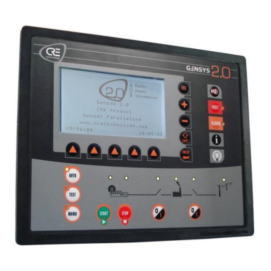
Figure 2 – GENSYS 2.0 front panel The display panel allows setting up and monitoring of the GENSYS 2.0 configuration and the power plant it controls. It provides a large LCD display and a keypad. See chapter below, for more details about the functions of LEDs &... -
Page 19: Table 3 - Display Panel Keys
4.1.1 Display panel The five dedicated keys of the display panel allow direct access to special menus or functions. See chapter “User interface” for more details concerning the functions of front panel LED and keys. Navigation mode Input mode (during parameter modification) Navigation Scroll / select menus and parameters. -
Page 20: Table 4 - Service Panel Keys
Pressing a second time on the same key will switch back to the menu displayed beforehand. LED test: pressing this key will turn on all GENSYS 2.0 LEDs. It is a simple test to Bulb check the LEDs and the keypad. -
Page 21: Table 5 - Control Panel Keys
4.1.3 Control panel The control panel allows the user to pilot and control the generator. See chapter “User interface” for more details concerning the functions of front panel LED and keys. Function upper This LED is illuminated when a key is pressed and is switched off when all keys right are released. -
Page 22: Table 6 - Control Panel Led's
4.1.4 Control panel led’s Function Engine Green LED lit when engine is running. Alternator Green LED lit when generator voltage is present. Genset breaker Green LED lit when generator breaker is closed. Mains breaker Green LED lit when mains breaker is closed. -
Page 23: Rear Panel - Connectors
4.2 Rear panel – connectors 4.2.1 Overview Figure 3 – Rear panel A53 Z0 9 0020 L En Technical documentation... - Page 24 4.2.2 Inputs/outputs Terminal capacity Terminal Description Comment (mm² / AWG) Supplied via emergency stop input at battery Crank relay out 2.5 / 12 positive voltage. Can also be used as configurable Output 6 relay output, see §10.4.2 5A max. Supplied via emergency stop input at battery Fuel relay out 2.5 / 12 positive voltage.
- Page 25 Terminal capacity Terminal Description Comment (mm² / AWG) Generator I1- 2.5 / 12 Generator I1+ 2.5 / 12 Generator current measurement 0 to 5A. Maximum rating: 15A during 10s. Generator I2- 2.5 / 12 1VA consumption. Generator I2+ 2.5 / 12 External current transformers are normally used.
- Page 26 Compatibility with Wheatstone bridge. Parallel. + 2.5 / 12 (shielded) Mainly used in applications with mixed equipments (e.g. GENSYS 2.0 with GCR or old ILS modules). See details in §10.9 Pickup - 2.5 / 12 50Hz to 10kHz. Maximum voltage: 40V...
- Page 27 Terminal capacity Terminal Description Comment (mm² / AWG) Compatible with most regulators. Details in §10.3 Shield 2.5 / 12 AVR out - 2.5 / 12 Mains breaker in 2.5 / 12 Digital input with 10kΩ pull-up dedicated to Mains breaker feedback. Accepts NO or NC contact to 0V.
- Page 28 COM1 CAN1 Male DB9 Isolated CAN© bus. (shielded) inter GENSYS 2.0 Proprietary protocol to communicate with other GENSYS 2.0/MASTER 2.0 units and share data/information. See details in §15.2. COM2 CAN2 options Male DB9 Isolated CAN bus (125kb/s factory setting). (shielded) J1939 See details in §15.3.
-
Page 29: Table 7 -Inputs/ Outputs Description
Terminal Description Comment (mm² / AWG) COM3 GENSYS 2.0 with firmware v2.00 (or later) : Type B This port is replaced by Ethernet communication. High Quality GENSYS 2.0 with firmware v1.xx : Isolated type B standard USB connector. Use a standard USB A to B cable to connect with PC. -
Page 30: User Interface
Remotely using dedicated CRE Config software or your favourite Internet Web browser. When GENSYS 2.0 is powered up, it displays a welcome screen during a short time and then switches to the display of the generating set’s status if emergency stop is activated. -
Page 31: Security Level And Password
Security level and password GENSYS 2.0 features password protected access levels to define which menu and parameters can be accessed. Table below details these levels and what can be accessed. Level Default password Authorization Accessible menu G59 (options) This is a special function access (see §13.10 for more details) No password. -
Page 32: Local Navigation
Display. Configuration. System. Figure 7 – Main menu 5.2 Local navigation The 5 icons above the contextual keys will change in appearance depending on the type of parameter to modify (chosen list, label, numerical value, password...). They are referred to as the “navigation bar”, or soft keys. -
Page 33: Figure 9 - Contextual Keys For Input Mode
In GENSYS 2.0 using firmware versions older than v4.00, parameters used in configuration are stored in a FLASH memory. When a parameter is changed by the user, the new value is stored in a RAM memory. The new value will be effective as soon as it is entered, but it will be lost if power supply is lost. -
Page 34: Remote Control Using Apc (Ethernet Connection )
5.3 Remote control using a PC (Ethernet connection) 5.3.1 Compatibility with CRE Config software Starting from firmware v3.00 GENSYS 2.0 can be monitored and controlled using CRE Config software. This software features a user friendly interface to monitor measurements and set up GENSYS 2.0 parameters. -
Page 35: Figure 11 - Typical Gensys 2.0 Web Pages
Web communication, the password will be asked for again. GENSYS 2.0 internal Web server is a very easy and efficient way of setting up your module. Various menus can be accessed via a Web browser such as Firefox or Internet Explorer as shown in the screenshots below. - Page 36 5.3.3 Downloading a text file When you are connected with a computer, a text file can be transferred between the GENSYS 2.0 and the PC. This allows the following actions: Upload new parameters to the GENSYS 2.0. Upload new equations to the GENSYS 2.0.
- Page 37 Properties. Enter the addresses as shown above. Note: IP address 192.168.11.100 shown above can be used if GENSYS 2.0 IP address is 192.168.11.1 (factory setting). Otherwise, computer and GENSYS 2.0 IP addresses should match the same subnet mask as shown below.
- Page 38 Notes on Ethernet connection If you change the IP address of a GENSYS 2.0, you should also adapt Windows hosts file to be able to use the hostname (http://gensys/ or any other hostname of your choice) in your Web browser. Otherwise you will have to directly type the IP address of the GENSYS 2.0 you want to connect to in your Web browser.
-
Page 39: Figure 12 - Ethernet Configuration Page
5.3.5 Changing GENSYS 2.0 IP address GENSYS 2.0 IP address can be changed in configuration page System/Communication ports config/COM4 (ETHERNET). Note: Once the new IP address is entered, you will need to restart the module for the new settings to take effect. -
Page 40: Operating Mode
GENSYS 2.0. If a speed governor is connected to GENSYS 2.0, it is possible to increase the speed with the [+] key, and decrease it with the [-] key. -
Page 41: Figure 13 - Assisted Manual Mode Without Main Paralleling
Depending on its setup (island mode, paralleled with Mains or other generating sets…), GENSYS 2.0 will automatically use the appropriate process: synchronization (if bus bar is live), closing the generating set’s breaker, loading ramp (if bus bar is live). Then it will manage the load depending on the setup (load sharing, fixed kW setpoint…). -
Page 42: Figure 14 - Assisted Manual Mode With Main Paralleling
(Change over, no break change over, paralleled with Mains…): GENSYS 2.0 will synchronize the generating set (if needed), close the Mains breaker, perform a load ramp… Then it will manage the load depending on the setup : load sharing, fixed kW setpoint…... -
Page 43: Automatic Mode
This mode allows testing automatic mode behaviour. When [TEST] key is pressed, the engine starts as if there was a remote start, and GENSYS 2.0 will carry out the standard Auto mode sequence. To exit “TEST MODE”, push [AUTO] or [MAN] key. -
Page 44: Semi-Automatic Mode
START button will automatically start the engine. The whole standard starting sequence is performed, and then the engine is let running at nominal speed without any other action from GENSYS 2.0. STOP button will stop the engine without performing any cool down sequence. -
Page 45: Manual Mode
The MANUAL mode replaces the ASSISTED MANUAL mode that is not available anymore. In MANUAL mode, it is possible to control the generator with the front panel of the GENSYS 2.0. All steps from engine start to paralleling are controlled by pushing keys. -
Page 46: Start Sequence
7 Start sequence During the start sequence protections are inhibited. This concerns all engine protections. When the engine reaches genset ready, the protections are activated. A timer can be added to inhibit protections during the "safety on" delay [E1514]. The timer will start when the genset is ready. Stop E1080 (Nominal Speed ) E1079 (Idle Speed ) - Page 47 Analogue sensors: The analogue oil pressure and water temperature sensors are used before start-up for the preheat and pre- lube checks: the water temperature [E0030]and oil pressure [E0029] must be ABOVE their respective thresholds (E1155 & E1154) for the engine to be allowed to start. The default setting for these thresholds is zero.
-
Page 48: Predefined Configuration
8 Predefined configuration 8.1 Single generator in change-over mode Figure 17 – Power plant in change-over mode without paralleling Variable Variable label Variable value number 1179 My Number 1147 Nb. of gen. 4006 Nb. of Master 1148 Mains parallel Change-over 1153 Mains regul. -
Page 49: Figure 18 - Typical Sequence In Change-Over Mode On Mains Failure
"Mains electrical fault". (See Figure 18) If remote start is on when mains are present the generator starts, GENSYS 2.0 opens the mains breaker, then closes the generator breaker and takes the load. (See Figure 19) -
Page 50: Figure 19 - Typical Sequence In Change-Over Mode On Start Request
E0022 (Mains voltage) E2201 (Start request on J3) E2000 (Mains breaker) E0003 (Genset voltage) E2001 (Genset breaker) Second Black First Black Figure 19 - Typical sequence in change-over mode on start request T1 : Genset ready T2 : Switch over delay [E1459] T3 : Switch over delay [E1459] A53 Z0 9 0020 L En Technical documentation... -
Page 51: Single Generator In No-Change-Over Mode
Fault start Table 10 - Typical no change over basic configuration In "No change over" mode [E1148] GENSYS 2.0 only starts on receiving a remote start signal and doesn't manage the mains breaker. A53 Z0 9 0020 L En Technical documentation... -
Page 52: Generator Paralleling With Digital Bus
Table 11 - Typical basic multi Generator configuration In this mode, CAN bus on COM1 “inter GENSYS 2.0" is used to manage the different units on the same bus. This mode has better reliability and accuracy than equivalent analogue solutions. -
Page 53: Generators Paralleling With Gensys 2.0 And Parallel Line Modules
Table 12 - Typical basic configuration for GENSYS 2.0 with parallel line modules When GENSYS 2.0 is in analog load sharing mode, the active power sharing is handled via the parallel lines. You have to disconnect the AVR output (H2-H4) and have an external device control the reactive power (CT droop...). -
Page 54: Multiple Generators With Static Paralleling
8.5 Multiple generators with static paralleling This mode is useful when you urgently need to start a full plant with multiple generators. The generators will be ready to take load in the shortest possible time. This mode is also very useful when your installation includes high voltage transformers. Starting generators which are paralleled together gives a progressive magnetization without peaks (no transient short-circuit). -
Page 55: Table 13 - Paralleling With Mains
One GENSYS 2.0 per generating set. CAN bus must be connected between GENSYS 2.0 units. An "Excitation" output (e.g. exit C1) must be configured on each GENSYS 2.0 unit. Generator breaker must be powered by 24VDC (so as to close without AC). -
Page 56: Single Generator Paralleled With Mains
8.6 Single generator paralleled with mains This function needs OPTION 2 to be installed. 8.6.1 Configuration Figure 25 - Paralleling with mains In permanent mode [E1148] and peak shaving mode [E1153], a mains power measurement is required: internal via L1-L6 inputs (Mains I1, I2, I3), ... -
Page 57: Figure 26 - Typical Sequence In No Break Co Mode On Start Request
When remote start is on, the generator starts, synchronizes and parallels with the mains, then takes the load (ramps up). Once the mains are unloaded, GENSYS 2.0 opens the mains breaker. (See Figure 26) When remote start is off, the mains takes the load in the same way as the generator did previously. If the generator started for a mains failure, when mains power returns the GENSYS 2.0 synchronizes the load... -
Page 58: Figure 27 - Typical Sequence In No Break Co Mode On Mains Failure
E0022 (Mains voltage) E2201(Mains failure) E2000 (Mains breaker) E0003 (Genset voltage) E2001 (Genset breaker) Black Figure 27 - Typical sequence in No Break CO mode on mains failure T1 : Fastest mains failure T2 : Switch over delay [E1459] T3 : Genset ready T4 : Mains back delay [E1085] T5 : Synchronization T6 : Unload ramp... -
Page 59: Figure 28 - Typical Sequence In Permanent Mode On Mains Failure
Permanent mode When the remote start is on, GENSYS 2.0 starts the generator, synchronizes and parallels with the mains, then ramps up load until it reaches its set point. (See Figure 28 & Figure 29) In base load mode (E1153=2), the generator has a constant load and the mains take the utility load variations. -
Page 60: Figure 29 -Typical Sequence In Permanent Mode On Start Request
E0022 (Mains voltage) E2201 (Start request on J3) E2000 (Mains breaker) E0003 (Genset voltage) E2001 (Genset breaker) Figure 29 -Typical sequence in permanent mode on start request T1 : Genset ready T2 : Synchronization T3 : Load ramp T4 : Unload ramp A53 Z0 9 0020 L En Technical documentation... -
Page 61: Power Plant Paralleled With Mains Using Master 2.0 Or Gcr
MASTER 2.0 gives a maximum of 31 generators. Mains paralleling mode is fixed to « No changeover » when a single GENSYS 2.0 is used together with one or more MASTER 2.0. A53 Z0 9 0020 L En Technical documentation... -
Page 62: Figure 31 - Gcr Gensys 2.0 Wiring Diagram
To allow Power Factor regulation, the "Mains breaker in" (J1) input to GENSYS 2.0 must be connected. Power Factor regulation is not an option. 8.7.1 Interfacing GENSYS 2.0 with GCR Figure 31 - GCR GENSYS 2.0 wiring diagram GCR (39-40) – GENSYS 2.0 (G4-G6): parallel lines (0-3V) to control active power. -
Page 63: Power Plant Paralleled With Several Mains Using Master 2.0 Or Gcr By Mains
8.8 Power Plant paralleled with several mains using MASTER 2.0 or GCR by mains Figure 32 - Power plant paralleling with several mains This application requires additional modules to manage the mains power supply. Additional modules can be MASTER 2.0 (recommended) or GCR (not recommended for a new installation). MASTER 2.0 uses all- digital technology whereas GCR uses analogue load share lines (sometimes called Parallel Lines). -
Page 64: Installing And Commissioning A Gensys 2.0 Application
9 Installing and commissioning a GENSYS 2.0 application 9.1 Minimum wiring diagram Figure 33 - Minimum wiring diagram A53 Z0 9 0020 L En Technical documentation... -
Page 65: Complete Wiring Diagram
9.2 Complete wiring diagram Figure 34 - Complete wiring diagram A53 Z0 9 0020 L En Technical documentation... -
Page 66: Installation Instructions
9.3.1 Mounting To secure the GENSYS 2.0 onto the panel, use the special kit provided with the module. The kit contains 4 screws, 2 brackets and 1 mounting tool. Figure 35 – Mounting kit Remove the connectors. -
Page 67: Figure 37 - Earth Grounding
Plug in the connectors. 9.3.2 Earth grounding Earth grounding of the GENSYS 2.0 should be made with two M5 screws & fan washers. Use a short 4mm² cable to connect the unit to earth (see below). Figure 37 - Earth grounding 9.3.3 Wiring guidelines... -
Page 68: Before Commissioning
Figure 39 - Interconnection of all battery negatives Rental fleet & Marine & HV generating sets CAN bus isolators are fitted inside the GENSYS 2.0 unit so it is possible to use it safely in MARINE applications and on rental fleets. - Page 69 Start the generator in [Manu] mode by pressing [Start] button. Press the generator breaker [0/I] key. The breaker should close (control OK) and the GENSYS 2.0 front face led should light up (feedback position OK). Press the generator breaker [0/I] Key.
- Page 70 Check that you are now in synchronization mode using the information screen key [i]. When the GENSYS 2.0 is ready to synchronize (synchroscope to noon), check that the phases match in upstream and downstream of the breaker. (i.e low voltage difference between phase n°1 generator and phase n°...
- Page 71 GENSYS 2.0 (Adjustment between 0 and 200%) For a GENSYS 2.0 in kW setpoint (base load or peak shaving), or in load ramp: In the « Configuration/Control loops/kW control/Ramp/Constant kW » menu, you can...
-
Page 72: Dedicated I/O Lines
The following procedure must be used to match the interface with the speed governor: Connect the speed ref. wire only (G11). Check that the negative speed governor power supply is shared with those of the GENSYS 2.0. Go to menu “Configuration/Engine/Speed control settings/Speed governor settings”... - Page 73 The Speed ref (G11) doesn't need to be connected if there is no voltage reference available. 0V must be wired with 4 mm² cable as follows: battery speed governor GENSYS 2.0. See table below for presets. For specific settings contact your dealer. Manufacturer Model Terminal...
- Page 74 Manufacturer Model Terminal Terminal Remark Amplitude offset G9 (out) G11 (ref) (1076) (1077) WOODWARD - 2301A/D 25.00% 25.00% Shunt 14-16 ILS+speed 90.00% Shunt 26 (com) - (Without on 0V U&I) 2301D 25.00% 00.00% G11 connected to 0v 2301A 99.00% -1.00% 16 connected Speed only to 0V...
-
Page 75: Figure 41 - Connection With Efc Cummins
Because of the very high sensitivity of Cummins EFC module input, please use the schematic below to connect your GENSYS 2.0 to the EFC. The resistors must be as close as possible of the speed governor terminal. This way, GENSYS 2.0 analogue speed output can be set higher (parameter E1076) according to the resistors used. -
Page 76: Figure 42 - Pwm Dynamic
Variable Label Value Description number E1639 500 Hz ACT Activates the speed control with 500Hz PWM. In this mode the analogue speed output (G9 / G11) is unavailable. E1077 ESG offset Is the PWM duty cycle set for nominal frequency. E1076 Is the range of the PWM duty cycle to control engine amplitude... -
Page 77: Speed And Voltage Control With Contacts/Pulses
Table 20 - Parameters speed and voltage control with Contacts / Pulses 10.2.2 Speed Calibration procedure Here follows the procedure for calibrating the +Hz and –Hz outputs on the GENSYS 2.0, necessary in order to have good frequency droop compensation and load sharing. (See Figure 45) ... - Page 78 [E1874] is too long. If you don’t get the desired compensation, check the following points: Is the potentiometer still running when GENSYS 2.0 sand an output signal? Est-ce que le potentiomètre tourne toujours si GENSYS 2.0 envoie un signal de sortie? ...
-
Page 79: Figure 45 - Speed And Voltage Control Pulses
10.2.3 Voltage calibration procedure Here follows the procedure for calibrating the +U and –U outputs on the GENSYS 2.0. The same procedure than the speed calibration procedure (see §10.2.2) has to be followed to calibrate the voltage control. (See Figure 45) -
Page 80: Analogue Avr (Auto Voltage Regulatior) Control
To set AVR control correctly: Start engine in [Manu] mode, Set Gain E1103:= 0 and Offset E1104:=0 on GENSYS 2.0. Set the AVR system to 400 VAC using its potentiometer. Enter maximum correction (E2038 = + 7000) with [Shift] + [+] buttons. - Page 81 See table below for preset settings. For specific setting contact your dealer. Manufacturer Model AVR gain AVR offset Termi Termi Comment [E1103] [E1104] nal H2 nal H4 STAMFORD MX341 A2 (+) A1 (-) Trim pot of AVR fully CW MX321 A2 (+) A1 (-) Trim pot of AVR fully CW...
-
Page 82: Table 22 - Avr Parameters
Manufacturer Model AVR gain AVR offset Termi Termi Comment [E1103] [E1104] nal H2 nal H4 R230 Remove the shunt input input - CATERPILLAR KVAR/PF 1.5kΩ in serial with H2 CDVR P12.6 P12.3 Table 22 - AVR parameters A53 Z0 9 0020 L En Technical documentation... -
Page 83: Relay Output
10.4 Relay output 10.4.1 Breakers GENSYS 2.0 is equipped with 4 NO relays (at rest) for breaker control: 2 relays to control the generator breaker - one for opening (E4) and one for closing (E5). 2 relays to control the mains breaker - one for opening (E1) and one for closing (E2). -
Page 84: Table 24 - Breaker Control Configuration
When GENSYS 2.0 tries to open/close a breaker, a maximum is allowed before getting the corresponding feedback from the breaker. This delay is set to 5 seconds (factory) and can be changed by adjusting parameter [E1149] in menu “Configuration/Modification by variable n°”. -
Page 85: Figure 48- Undervoltage Coil
Working of pulse or an undervoltage coil For control using a pulse or an undervoltage coil, the necessary parameters are: [E1893]: pulse length. [E1994]: Undervoltage coil delay. This sets the time between the opening of the breaker and the closing of the undervoltage coil control contact. -
Page 86: Crank/Fuel/Starter 2/ Starter 3 Functions
10.4.2 Fuel & Crank The standard functions for these two relay outputs are for normal Fuel and Crank relay applications. Crank is A1 (OUTPUT 6), and Fuel is A2 (OUTPUT 7). These two outputs are relays and are fully configurable through the “Configuration/outputs / Relay outputs”... -
Page 87: Water Preheat/ Pre-Lubrication/ Pre-Glow Functions
Preheat is active when J7 is closed. The water temperature sensor isn’t required. Pre lubrication is active when J8 is closed. The oil pressure sensor isn’t required. Pre glow is active when J9 is closed, when you push GENSYS 2.0 start button, or if J10 is closed. 10.6.2 Automatic mode Pre-heat is activated if J6 is closed and if temperature is under the pre-set threshold (E0030 <... -
Page 88: Air Fan
10.7 Air fan GENSYS 2.0 J5: water temp input Output 1: C1 Air fan relay F6 / F7 Water temperature Output 1 function [E1260] = Air fan (2215) sensor Figure 50 - Connection for air fans In all cases, the AIR FAN will be activated if J5 is activated or if the “max water temp” protection (F6/F7 analogue input) is configured and triggers. -
Page 89: Fuel Filling/ Coolant Filling/ Oil Filling
10.8 Fuel filling/ Coolant filling/ Oil filling GENSYS 2.0 J6: Input 1: Fuel low level (2230) J7: Input 2: Fuel high level (2231) J8: Input 3: Manu fuel fill (2252) Fuel fill relay J9: Input 4: Coolant low level (2243) -
Page 90: Figure 52 - Fuel Filling Diagram
The parameters « Filling input » allow selecting the resistive sensor to use among: Analog input 1 (F1-F2) : set filling input parameter to 31 Analog input 2 (F3-F4) : set filling input parameter to 32 Analog input 3 (F6-F7) : set filling input parameter to 30 ... -
Page 91: Analogue Load Sharing Line
Note : Don’t forget to configure output 1 in “Used by equations”. 10.9 Analogue load sharing line It is possible to use traditional analogue load sharing lines (often called Parallel lines) with the GENSYS 2.0 product. The example shown is in association with a BARBER COLMAN product. -
Page 92: Watchdog Output
Watchdog output A watchdog option is available using the C5 output. This option must be specified upon ordering your unit so that CRE Technology can activate it. For more information concerning this function, please contact CRE Technology. A53 Z0 9 0020 L En Technical documentation... -
Page 93: O Lines
11 I/O lines 11.1 Digital input They are divided into dedicated and configurable inputs. For Digital inputs (J4 to J15) the following parameters can be set: Label: can be modified with parameters file. Validity: can be modified using configuration menu or equations. ... -
Page 94: Table 28 - Input Validity Domain
Never active: should be selected if you do not use the input. 2329 Always Always active: input will be monitored as long as GENSYS 2.0 has power. 2192 Post-Start Input will be monitored at the end of the "safety on delay” [E1514] 2331 Stabilized Input will be monitored when genset is ready for use. - Page 95 This will have the same effect as pressing 2205 Fault reset request the reset key on the GENSYS 2.0 front panel on Fault and Alarm displays. To be selected if a remote start command is to be 2227 Manual start request installed.
- Page 96 Will inhibit the "Manu" key on the GENSYS 2.0 front 2260 Auto mode forced panel. GENSYS 2.0 will never be in Manu mode even if you press the GENSYS 2.0 "Manu" key. Will put GENSYS 2.0 into Manual mode. Will have the...
-
Page 97: Digital Outputs
11.1.6 Dedicated inputs In the menu list, each input is named after its pin number on the wiring of GENSYS 2.0. Polarity can be normally open or normally closed. Program this according to the wiring you will have on site. - Page 98 GENSYS 2.0. Hard shut down Will activate an output when there is at least one “serious 2204 summary fault” (securities) triggered by GENSYS 2.0. Soft shut down Will activate an output when there is at least one “minor fault” 2203 summary triggered by GENSYS 2.0.
- Page 99 The behaviour will change according to the mode. In Manual mode, if you program the +f function, the output will be 2341 activated when you press the GENSYS 2.0 [+] key or if there is a “Manual +f request” [E2233]. Likewise for the other functions; - 2342 f activates with [-] key or “Manual –f request [E2234];...
- Page 100 This will activate the output whenever the light test key is 2232 Lamp test pressed on the front panel of GENSYS 2.0, or an input programmed for light test is active Output will be active when start sequence is completed and voltage is present at the generator.
-
Page 101: Analogue Input (Via Cre Config Software)
- can be used for external logic. The output will 2525 GE available be activated when GENSYS 2.0 is in Auto mode and the power state [E2071] is not in fault. Heavy consumer Output activated when heavy consumer starting is allowed in... -
Page 102: Table 32 - Oil Pressure Calibration Points
0.001 11.3.2 Water temperature configuration You can now choose units (°C or °F) and degree of accuracy (number of digits after decimal point): 0.01 0.001 11.3.3 Configuration of engine measurements 1 and 2 Spare Analogue measurements 1 and 2: they can be named, and the unit to be displayed chosen among the following: No unit, V, kV, mA, A, kA, Hz, kW, kWh, kVAR, kVARh, rpm, %, Bar, mBar, kPa, PSI, °, °C, °F, L, Gal, s, h, days, Hz/s, m3/h, L/h, Gal/h. -
Page 103: Table 33 - Water Temp Calibration Points
Ohm VDO 120° VDO 150° Veglia Datcon L Datcon H AC 1000 1000 1000 1000 Table 33 - Water Temp calibration points Engine measurements 1 and 2 Spare 1 engine measure calibration points are [E1210 to E1220]. Spare 1 engine measure impedance points are [E1188 to E1198]. Spare 2 engine measure calibration points are [E1232 to E1242]. - Page 104 GENSYS 2.0 -BAT Parameters Calibration table for a normally closed input: V1210 Spare1 calib1 -32768 +32767 V1211 Spare1 calib2 -32768 +32767 V1212 Spare1 calib3 -32768 +32767 V1213 Spare1 calib4 -32768 +32767 V1214 Spare1 calib5 -32768 +32767 V1215 Spare1 calib6 -32768...
- Page 105 @*********************************; @analog input to DI/spare 1 ; @*********************************; @E0031 analog input spare 1; @E2283 virtual input 1 ; @*********************************; E2283:= E0031 ; Calibration table is similar for a normally opened input; you need only change the equations: @*********************************; @ Analog input in numeric/spare 1 ; @*********************************;...
-
Page 106: Protections
CAN bus. When the helping set is connected to the busbar (and not before!) GENSYS 2.0 will open the genset breaker, allowing the engine to cool down off load, for the duration of the cool down timer. The engine is then stopped. -
Page 107: Help + Gen. Electrical Fault
Before opening the corresponding breaker, GENSYS 2.0 will call another genset onto load via the inter- GENSYS CAN bus. When the helping set is connected to the busbar (and not before!) GENSYS 2.0 will open the corresponding breaker and try to synchronize again. The number of attempts can be configured. - Page 108 E2546 MA min kW Mains reached a minimum of kW. E1422 E2550 MA max kW Mains reached a minimum of kW. E1425 E2172 Over speed Engine is in over speed E1162 E2176 Under speed Engine is in under speed E1165 The oil pressure reached the minimum E2180 Min oil press.
- Page 109 E2569 Virtual in 25 E1684 E2570 Virtual in 26 E1685 E2571 Virtual in 27 E1686 E2572 Virtual in 28 E1687 E2573 Virtual in 29 E1688 E2574 Virtual in 30 E1689 E2575 Virtual in 31 E1690 E2576 Virtual in 32 E1691 E2577 Virtual in 33 E1692...
-
Page 110: Table 34 - Potential Alarm/Fault List
High water temperature detected by J1939- E0343 High Cool T E1859 E0355 Very Low Oil P Very low oil pressure detected by J1939-MTU. E1860 Very high water temperature detected by E0356 Very Hi Cool T E1861 J1939-MTU E0358 Hi Overspeed High overspeed detected by J1939-MTU. -
Page 111: Additional Functions
The set point of the central frequency is the parameter [E1080] (or [E1081] if selected). When the GENSYS 2.0 starts, one genset is elected to be the master (the first one on the bus). The master determines the central frequency and load sharing is without an integral. The other gensets determine the load sharing with an integral, but without using the central frequency. - Page 112 Notes: [E1902] = stability of de-drooping (only activated in the master GENSYS 2.0). Adjust to recover 1Hz within 5 sec. [E1476] = 0 Inhibition of central frequency. [E1476] = with a high value, response time will be slower (recommended default value =2) [E1901] = Load sharing integral, is only active on the slave GENSYS 2.0 units.
-
Page 113: Operator Controlled Return To Mains
V1476 XXXXXX V2739 Master If 1 this GENSYS 2.0 is the master. gen. Nb Table 35 –Integral inhibition Warning: When the CAN bus is not used, you have to disable load sharing (see table above). In the case of a CAN bus failure where [E1259] is not set at 6 (load sharing in droop disabled), you also have to disable load sharing. -
Page 114: Figure 55 - Change Over With One Digital Input Setup As "Mains Electrical Fault
(1) available in « Configuration/Mains/Bus/Mains electrical fault» menu. (2) modification by variable number. Chronogram below shows the behaviour when using change over mode. Start on Mains electrical fault (E1841) is set to Yes Generating set circuit breaker (E2001) Mains circuit breaker (E2000) Digital input set as Mains electrical fault... -
Page 115: Generator Electrical Fault
In case of a generator electrical fault, the generator breaker is opened and the alternator is de-excited (if wired) during a certain time [E1265]. If the fault is still present after this time has elapsed, a hard shutdown occurs. Otherwise GENSYS 2.0 will try to re-synchronize. Associated parameters are listed in the table below. -
Page 116: Gensys 2.0 With External Automatic Start Module
13.5 GENSYS 2.0 with external automatic start module 13.5.1 Overview This chapter describes how to interface GENSYS 2.0 with an engine featuring its own automatic start module. In this case GENSYS 2.0 internal start sequence must be inhibited. The following diagram shows the main functions of each device: Note: starting from firmware v4.00, GENSYS 2.0 features an easy configuration whereas older firmware... -
Page 117: Figure 59 - External Start Sequence
Case 2: external start module doesn’t feature any “Generating set ready” logic output. GENSYS 2.0 will have to wait for the lower voltage [E1028] and the lower engine speed [E1163] are reached to go in speed stabilization [E1140] then in voltage stabilization [E1141] to consider the generating set is ready. -
Page 118: Remote Start Upon External Pulse
E2514:=((E2514 OR ((E2815 EQ 1) AND (E2585 EQ 0))) AND ((E2514 AND ((E2815 EQ 1) AND (E2585 EQ 0))) EQ 0)) BEND Do not forget to set the input. GENSYS 2.0 must be informed that J15 (in this example) is used by a custom equation: V1276... -
Page 119: Safety Inhibitions
(norm NF E 37-312). The aim is to inhibit the oil pressure and water temperature safeties on the GENSYS 2.0. Thus, in the case of a fault, the generator remains in operation. Other protections (over speed, overload, etc...) are still active if set. - Page 120 BLOC @***************************************************************; @ Oil pressure and water temp Inhibition @***************************************************************; @E2811 Logical Input J11 GENSYS 2.0 inhibit security @E2812 spare input 8 J12 oil pressure @E2813 spare input 9 J13 is water temperature @E1273 fct spare input J12 @E1274 fct spare input J13...
-
Page 121: Use Of Bsm Ii With Gensys 2.0
GENSYS 2.0 can be connected to several devices via its COM2: BSM II (Max 2), Wago coupler (Max 32). Only one of the two BSM II must be set to log data from GENSYS 2.0 (limited by the number of messages sent from GENSYS 2.0). - Page 122 Change the Node ID of BSM II See BSM II user's manual to choose the node ID in the BSM II. Then change this node ID (Output address) in the settings of the GENSYS 2.0 (default ID equal 1) via the CRE Config software.
- Page 123 Set “Number of Outputs” (Max 4) Add equation described below Customize the variables sent to BSM II All variables are transferred as analogue outputs from GENSYS 2.0 to BSM II. Analogue output GENSYS 2.0 Variable AO1 AO8 E2432 E2439 AO9 ...
-
Page 124: Gensys 2.0 With Tem Compact
This chapter describes how to interface the GENSYS 2.0 with the TEM compact from Deutz Engines. The association of the TEM and the GENSYS 2.0 is an excellent solution to parallel a generator set with a Deutz Engine prime mover. -
Page 125: G59 Norm (Access Level -1)
When the protections are locked, thresholds, timers and controls are also locked. 13.11 Scada GENSYS 2.0 communication uses industrial standards. This product is versatile, and can be used with Modbus, for example to be controlled by a SCADA system. CRE Technology offers different solutions for such applications (remote display, remote control, event and alarm management …). -
Page 126: How To Set Agpid
13.12 How to set a GPID 13.12.1 Principle A GPID allows the control of any system in a simple way. Figure 51 shows a typical GPID. Set Point Deviation Measure G: global gain P: proportional gain I: integral gain D: derivative gain Figure 62 - Typical GPID controller The G parameter acts as sensitivity adjustment for the other parameters. -
Page 127: Automatic Load / Unload
If a digital or virtual digital input of one GENSYS 2.0 is set as priority generator, this GENSYS 2.0 will start first. The next to start will be decided by increasing genset number, which is defined in the power plant overview settings menu. -
Page 128: Figure 63 - Automatic Load/Unload
When all generators are stopped and have "remote start" activated, upon start-up the "Forced running"" generators stay on the bus bar while the others coordinate stopping one by one. Hours run: [2] ; the genset to start/stop will automatically be selected according to the GENSYS 2.0 hour meter. -
Page 129: Table 40 - Parameters Load/Unload Threshold
TM before load Timer for load sharing request. [E1257] Unload thresh. Percentage of the genset nominal power at which GENSYS 2.0 will ask a [E1254] genset to stop sharing the load. TM bef. unload. Timer used before deciding to reduce the number of gensets in [E1255] load/unload management. -
Page 130: Figure 65 - Unload According Power
Load/unload according to power The goal is to avoid that a large number of parallel generators are running just above the unload threshold. Ex: 4 generators are running at 35% while 2 generators can supply this power with 70% each. In this mode, each unit calculates the power that will remain on the bus bar (in % for each engine remaining) if it decides to stop (and open its breaker). -
Page 131: Heavy Consumer (Marine Sequence)
This function can be configured by CRE Config software. This function is used in Marine applications. Some external parameters must be analysed by the GENSYS 2.0 units before accepting heavy consumer load. If Power Plant can accept load, each GENSYS 2.0 accepts load. -
Page 132: Figure 66 - Heavy Consumer Control With Active Power Analysis
Power Plant = 2 GEs of 100 KW each Heavy Consumer demand Heavy Consumer = 75 KW time KW of Power Plant 200 KW 100 KW time KW available Start and Synchronisation of second GE 100 KW time Heavy Consumer authorization time Figure 66 - Heavy Consumer Control with active power analysis Power Plant = 3 GEs... -
Page 133: Non-Essential Consumer Trip (Marine Sequence)
This function can be configured by CRE Config software. This function is used in Marine applications. If the generator reaches the overload or under frequency threshold (following timers), GENSYS 2.0 triggers outputs to trip non-essential loads. This chapter will describe how to use these features. -
Page 134: Figure 68 - Non Essential Consumer Trip Alarm (1)
E2729 is activated timer 1 E2729 is activated timer 2 Figure 68 - Non essential consumer trip alarm (1) Min Hz 1 E2729 is activated timer 1 Min Hz 2 Min Hz 1 E2729 is activated timer 2 Min Hz 2 Figure 69 - Non essential consumer trip alarm (2) A53 Z0 9 0020 L En Technical documentation... -
Page 135: Figure 70- Non Essential Consumer Trip Output Setting
Configuration of the trip output (/Configuration/Outputs/Digital outputs): Figure 70- Non essential consumer trip output setting When the variable [E2729] is activated, each trip output will activate after the same timer [E1894]: E2728:=1 E2727:=1 E2727:=1 E2726:=1 E2726:=1 E2726:=1 E2725:=1 E2725:=1 E2725:=1 E2725:=1 E2724 : =1 E2724:=1... -
Page 136: Phase Offset (Dyn11 And Other)
13.16.1 Introduction This advanced function, available with option 8, provides a choice of phase offset [E1929] between mains and generator voltage measurement. That means that GENSYS 2.0 will command the breaker to close with the selected phase angle shift. Figure 73 - Phase offset example You must take care before choosing this function and modifying the phase offset parameter. -
Page 137: Voltage System (120° Three Phases , 180° Two Phases , Single Phase )
13.17 Voltage system (120 three phases, 180 two phases, ° ° single phase) Parameter [E4039] allows you to select the system to be used in the “Configuration/Power plant” menu. System used E4039 Three phase 120° 0 (default value) Two phase 180° Single phase Table 44 - Voltage system SYSTEME... -
Page 138: Maintenance Cycle
13.18 Maintenance cycle Here you can setup custom cycles called maintenance cycles. User can set them up to schedule maintenance operation after the desired amount of running hours or days. 5 cycles are based on running hours timers, 5 cycles are on a day basis. To configure the maintenance cycle uses the CRE Config software or the parameters file. -
Page 139: Front Panel Inhibition
13.19 Front panel inhibition Specific parameters can be setup and monitored to control each front panel button individually. Parameters [E0892] to [E0913] contain the status of the front panel button, a value of 1 means that the key is pressed while 0 means the key is released. Variables [E4043] to [E4064] are set to 1 to inhibit the use of selected front panel buttons. -
Page 140: Text File & Plc
14 Text file & PLC 14.1 Introduction GENSYS 2.0 LT doesnt’ support the custom equation. All references to equation in this chapter are not applicable for GENSYS 2.0 LT. The core system of the module is based on a list of predefined variables. -
Page 141: Text File Description
This can be done either: 1. By a computer connection to the embedded Web site in “System/GENSYS 2.0 -> PC file” menu (See §17.4.6 for more details) 1. By the front panel LCD using an SD card in “System/Communication ports config./COM6(SD CARD)”... -
Page 142: Table 46 - Label Definition Bloc
{PARAMETERS} V1006 320 Y Gen nominal kW +00000 +65535 V1007 1.00 N Gen PT ratio +00000 +65535 In the example above, Genset nominal power is set to 320kW. The Y attribute shows that this value can be changed by MODBUS or custom PLC equations whereas the N attribute in the second line sets Generator PT ratio as "read only"... -
Page 143: Table 47 - Custom Logo Labels
Logo page labels T0249 GENSYS 2.0 T0250 CRE product T0251 Genset Paralleling T0252 www.cretechnology.com Table 47 - Custom logo labels Each line of this block contains 2 elements: -The variable number of the text, preceded by the letter L for label, and T for page logo. -
Page 144: Table 48 - Accuracy Codes
{UNITS} U0029 U2584 A0029 0000032768 The tables below give you the list of codes which correspond to the supported units and accuracies. In the examples above, input E2584 has no specific unit while input E0029 will be displayed in Volts (Unit code 01) and with 2 decimal digits (Accuracy code 32768). - Page 145 Code Variable Default Default Description Label number unit code accuracy code 0289 16384 analogue input 5 Analog in 05 0290 16384 analogue input 6 Analog in 06 0291 16384 analogue input 7 Analog in 07 0292 16384 analogue input 8 Analog in 08 0293 16384...
-
Page 146: Table 50 - Variables With Customizable Unit/Accuracy Values
Code Variable Default Default Description Label number unit code accuracy code 2289 00000 Virtual input Spare 7 Virtual in 07 2290 00000 Virtual input Spare 8 Virtual in 08 2291 00000 Virtual input Spare 9 Virtual in 09 2292 00000 Virtual input Spare 10 Virtual in 10 2293... -
Page 147: Plc Programming Language
INIT equations are only run once by the PLC when it is powered on. They won’t be run again until power supply is switched OFF and ON again. INIT blocks are typically used to set the initialization values of outputs, timers or counters associated to custom equations or custom parameters. For further details on the programming language see §14.4. - Page 148 followed by level 2 equations. This way, level 2 equation results can overwrite any conflicting level 1 equation. The "INIT" part is only executed upon start-up, and the "PROG" part is executed every 100ms. All the module variables can be used in the equations in the way defined below: -E0xxx and E5xxx are read only as measurements/inputs.
-
Page 149: Variables
Instruction family PLC instruction Definition Affectation Affectation Comparison operators Equal Not Equal Greater Than Less Than Greater or Equal Less or Equal Array [...] Array element Tests TEST THEN ELIF ELSE TEND Comments Table 51 - Available instructions Instructions are separated by a semicolon (;) except before reserved words BEND, ELIF, ELSE and TEND. INIT and PROG blocks are terminated by a dot (.). -
Page 150: Syntax Examples
When the cycle controller, checks the validity module (range min / max) values of variables X2nnn. If the value is legal, it is kept in memory for further operation. If the value is invalid, the internal variable will retain the value it had just before the PLC cycle ( the value E2nnn). Note that as the first set is a picture of the variables before execution of the equations, it can be viewed as “read only”. - Page 151 {INIT L2} INIT 2 BLOC E2440 := E1710; E2441 := 0; E2442 := 1 BEND {EQUATIONS L2(every 100ms)} PROG 2 BLOC @ E2440 is used as a counter that decreases from parameter E1710 down to 0; TEST E2440 GT 0 THEN DEC E2440 ELSE E2440 := E1710...
-
Page 152: Gensys 1.0 - Gensys 2.0 Compatibility
14.7 GENSYS 1.0 – GENSYS 2.0 compatibility Using a GENSYS 1.0 configuration file in a GENSYS 2.0 unit is a risky operation and requires excellent knowledge of the parameters and equations transferred. New functions have been added to the GENSYS 2.0 which use new variables. Certain GENSYS 1.0 variables have been redefined with new functions in the GENSYS 2.0. - Page 153 The parameters listed above are shown with their default settings for the GENSYS 2.0. If your configuration file or variables modify these parameters, make sure their use is the same as in the GENSYS 2.0. A53 Z0 9 0020 L En Technical documentation...
-
Page 154: Resetting To Factory Parameters
14.8 Resetting to factory parameters This function, only available in level 2, gives you the ability to reset your module into its factory configuration, thus erasing all changes made since the first use of the module, erasing all parameter changes and custom PLC. This can be done either from front panel or embedded Web site in menu “System/Reset factory settings”. -
Page 155: Communication
Figure 75 - Network topologies Both ends of the CAN bus must be terminated with 120Ω resistors. Such resistors are fitted into GENSYS 2.0 COM1 and COM2 and can be activated using DIP switches at the rear of the module under the “OFF / 120Ω”... -
Page 156: Figure 76 - Example Of Can Connection Between 3 Modules
Figure 76 - Example of CAN connection between 3 modules CRE Technology provides a complete range of products aimed at installing your CAN bus (complete cables, wires, connectors…). Please contact your local CRE Technology distributor to help you choose adequate equipment to fit your needs. -
Page 157: Com1: Cre Technology Inter-Modules Can Bus
15.2 COM1: CRE Technology Inter-modules CAN bus This CAN bus is used as a communication means between modules (GENSYS 2.0/MASTER 2.0) from a single power plant. Features are: Active and reactive load sharing. Automatic load/unload. Static paralleling. -
Page 158: Figure 77- Example Can Bus Fault
If a remote start occurs on a GENSYS 2.0 working in automatic mode and set up to manage Deadbus situations (E1515 = 0) and a CAN bus fault has already been triggered, GENSYS 2.0 will start its engine and close its breaker (if there is no voltage on the bus bar) after a delay that depends on the generator number [E1179]. -
Page 159: Table 56 - Broadcast Data Sent On Inter Module Can Bus
2 (Engine Meas. 1 on terminal F1-F2). So fuel level is measured and stored in variable [E0031] of module number 2. You may broadcast this fuel level to the 3 other CRE Technology modules by adding the following custom equation into module number 2: X2762:= 31;... -
Page 160: Table 57 - Broadcast Data Received From Inter Module Can Bus
In this example, two GENSYS 2.0 are connected together using CAN bus COM1. Both units (GENSYS 2.0 #1 and GENSYS 2.0 #2) send two broadcast variables to each other on the CAN bus, one variable being digital input J6 (E2806) and the other one being analogue value E0033 (engine speed). -
Page 161: Figure 79 - Analogue And Digital Data Broadcast Example
120Ω Figure 79 - Analogue and digital data broadcast example To send desired data on CAN bus the following equations should be used on both GENSYS 2.0 units: BLOC @Send input J6 on CAN bus using first digital broadcast data;... -
Page 162: Table 59 - Can Bus Inhibition Variables
Ignore power management data from GE32 Table 59 - CAN bus inhibition variables If one of these variables is set to one, power management data from the corresponding GENSYS 2.0 will not be taken into account. A53 Z0 9 0020 L En Technical documentation... -
Page 163: Figure 80 - Can Bus Inhibition Schematic (Example)
When the tie breaker is closed, each GENSYS 2.0 communicates with the 3 other units. When the tie breaker is open, all GENSYS 2.0 units need to know that they have to consider the power plant differently, with two separate bus bars. This is where we will use CAN bus inhibition. -
Page 164: Com2: Can Protocols (Canopen, J1939, Mtu Mdec)
15.3 COM2: CAN protocols (CANopen, J1939, MTU MDEC): GENSYS 2.0 LT doesn’t support CANopen communication on COM2. The COM2 port is a CAN bus communication port allowing to communicate with: Industrial extension modules CANopen (§15.3.1) electronic ECU using J1939 (§15.3.2) ... -
Page 165: Figure 81 - Modular Remote Canopen I/O Extension Module
An end resistor of 120 must be connected to each end of the cable between CANH and CANL. This resistor exists inside GENSYS 2.0 and can be activated with a switch accessible from the rear of the unit and located under the plug marked “OFF / 120Ω”. -
Page 166: Table 61 - Canopen Input And Output Variables
System configuration CANopen communication uses CANopen messages that can be set up in the “Enhanced configuration/CANopen” menu. GENSYS 2.0 can handle a total of 13 input messages and 19 output messages. Three parameters must be set for each message to be used. Each message is determined by: ... -
Page 167: Table 62 - Canopen Configuration Example
CANopen mapping example In this example, 3 CANopen modules are connected to CAN bus COM2 of GENSYS 2.0. All these modules offer different kinds of input. CANopen Physical I/O on the CANopen CANopen input Input coupler extensions message setup variables Message n°1... -
Page 168: Table 63 - J1939: Analog Measure Or J1939
Set the Alarm/fault (See below) Connect the CAN bus between the engine ECU and the COM2 port of the GENSYS 2.0 (see §15.1 for more details) The internal configuration of the module will be directly set according to the manufacturer/ECU pair: ... -
Page 169: Table 64 - J1939: Manufacturer/Ecu List
By default, the output relay FUEL is inverted for the SCANIA engines. If need the output can be set to initial state by setti ng the output relay FUEL as « Unused ». On IVECO engine, the ECU is powered by the output FULE of the GENSYS 2.0. The output CRANK is activated with a 2 seconds delay (by default) settable by [E4079]. - Page 170 J1939 measures If a J1939 engine is selected, the module is able to read the following information. They are displayed on 5 pages on the « Display/Engine meters » menu. To get more information on these measures (unit, accuracy…), see the J1939 norm « SAE J1939-71 ». Measure Description FUEL_RATE...
- Page 171 Measure Description CRANK_CASE_PRESS 0xFEEF Gage pressure inside engine crankcase [E2882] OIL_LEVEL 0xFEEF Ratio of current volume of engine sump [E2871] oil to maximum required volume FUEL_DEL_PRESS 0xFEEF Gage pressure of fuel in system as [E2870] delivered from supply pump to the injection pump FAULTS 0xFECE...
-
Page 172: Table 65 - J1939: Measurement List
Measure Description ACTUAL_TORQUE 0xF004 The calculated output torque of the [E2852] engine. The data is transmitted in indicated torque as a percent of reference engine torque DD_TORQUE 0xF004 The requested torque output of the [E2851] engine by the driver. It isbased on input from the following requestors external to the powertrain: operator (via the accelerator pedal),cruise control and/or... -
Page 173: Table 66 - Unknown Spn/Fmi
In addition of these measures, the module display the last five 5 unknowns SPN/FMI, which have been received by the module with the diagnostic message (DM1). The known SPN are described below in the 1939 Alarm/Message chapter. These SPN/FMI are backup in the following parameters. Parameter Description J1939 SPN LO 1... -
Page 174: Table 67 - J1939: Alarms/Faults List
GENSYS 2.0 fault/alarm system. GENSYS 2.0 is able to understand and interpret messages for display, process, and protection. RESET message (DM3) is sent to the engine when internal GENSYS 2.0 RESET is activated ([RESET] button or internal variable). -
Page 175: Table 68 - J1939: Trames Rx Custom
This feature is designed for experienced user. A wrong configuration could damage your generator. If needed, a custom frame can be sent by the GENSYS 2.0 to the J1939 device. To configure your Tx custom frame, see the frame n°2 configuration of a Custom engine (see below the chapter Custom engine) Note : There are no web pages to configure these TX custom frames. -
Page 176: Table 69 - J1939: Custom Engine Configuration
Custom engine WARNING: This feature is designed for experienced user. A wrong configuration could damage your generator. When selecting the Custom engine, you can configure 2 frames to send by J1939. Use custom PLC equations to access custom TX variables that are described below. frame number Variable Description... - Page 177 Note: Selecting MTU MDEC communication prevents you from using extension remote I/O modules. MDEC configuration To correctly communicate with GENSYS 2.0, MDEC internal variables have to be configured. The MDEC should be configured as follows to activate the CAN communication: ...
-
Page 178: Figure 83 - Mdec: Gensys2.0 Connexion
CAN ground COM 2 pin 5 Analogue speed command Analogue speed reference 31 (5V ref) Table 70 - MDEC connexion Useful GENSYS 2.0 parameters are listed below to ensure proper communication with the MDEC module: Variable Label Value Description number... -
Page 179: Table 71 - Important Parameters
Table 71 - Important parameters (1) The standard sensors required for oil pressure, water temperature and engine speed don’t need to be connected to GENSYS 2.0. The value of these 3 analogue inputs (E0029, E0030, E0033) will be taken from the MTU CAN bus. -
Page 180: Figure 84 - Mdec Screens
Figure 84 – MDEC Screens Additional information In the standard configuration GENSYS 2.0 can display all the MDEC variables available on the CAN bus thanks to the screen seen above. These variables are displayed ‘as is’ without any further processing, except for certain faults. - Page 181 If you set [E1857] as security (E1857=5) and [E0332] is set to 1, then [E2204] (hard shut down) will also be set to 1 and trigger the hard shutdown process. If you want to use an MDEC alarm that is not handled directly by GENSYS 2.0, you can use a virtual input as described in the following example: If you want to handle an MDEC alarm for “SS Power Reduction Active”...
-
Page 182: Com3: Usb
15.5 COM4: ETHERNET The Ethernet port features the following communication possibilities: Visualization and configuration of GENSYS 2.0 via its internal Web site, or using CRE Config software (starting from GENSYS 2.0 firmware v3.00). Modbus TCP control of GENSYS 2.0 using SCADA equipment. - Page 183 15.5.2 Copyright GENSYS 2.0 Ethernet communication uses the open source lwIP TCP-IP stack. Please see the copyright/disclaimer below. More details can be found on lwIP Web site: http://savannah.nongnu.org/projects/lwip/ Copyright (c) 2001-2004 Swedish Institute of Computer Science. All rights reserved. Redistribution...
-
Page 184: Com5: Modbus Rtu On Serial Port Rs485
As said above, parameters E1nnn are set to READ ONLY. Write access can be done on a ‘per parameter’ basis using a configuration text file sent by PC to the GENSYS 2.0. Please refer to §14.3.2 for more details on this Read/Write attribute. -
Page 185: Table 73: 32 Bits Variables (Use Function 0X10)
Table 73: 32 bits variables (Use function 0x10) GENSYS 2.0 registers start from address 0. Depending on your MODBUS master equipment and software, you may need to use an offset of 1 when reading/writing registers as addresses may start from address 1. -
Page 186: Table 76 - Modbus Parameters For Alerm/Fault Management
CRE Technology module. Note: Data available concerns only faults that appeared after the last power up sequence. Events appeared before GENSYS 2.0 was switched OFF and ON again will be listed in the FAULT pages but not inside those variables. -
Page 187: Table 77 - Modbus Communication Example
Modbus communication example: Table below gives an example of a MODBUS master sending a reading request (function 04) of 3 registers starting from variable E0007. This request is sent to a GENSYS 2.0 setup as slave number 5. MODBUS RTU request/answer example Master request GENSYS 2.0 slave answer... -
Page 188: Com6: Sd Card
15.7 COM6: SD card GENSYS 2.0 is equipped with a SD card slot that adds different functions using a FLASH memory SD card. backup Firmware upgrade Import/Export a text file Table below details what kind of SD card can be used depending on firmware version installed into your module. - Page 189 Note: If the variable [E4041] is set to 0, the recording stops. NOTE Do not remove the SD card from its slot when it is being accessed by GENSYS 2.0 or it may corrupt your file. To avoid damaging data, make sure to: ...
- Page 190 Select the first column (A) with saved values. Click on "Data", then "convert". Select "limited". Select Table, Comma and Semicolon. Click "Next". The variables, values, dates and times are now laid out in columns. A53 Z0 9 0020 L En Technical documentation...
-
Page 191: Table 78 - Sd Card Backup - File Size
The backup file size is computed from the following equation : Here some file size examples. Number of Recording time Recording period File size variable 780kbytes 1,5Mbytes 5min 8,1kbytes 30 days 22,5Mbytes Table 78 – SD card backup – File size 15.7.2 Firmware upgrade using SD card Starting from firmware v3.00, it is now possible to upgrade the firmware with a new version using a computer, the embedded Web site and an SD card. - Page 192 Backup parameters and equations if necessary. Copy the new firmware on an SD card and insert it into the module. Filename must respect format XXXXXXXX.H86 and the file should be provided exclusively by CRE Technology or its distributor network.
- Page 193 Note: If your module was setup for DHCP usage on Ethernet, bar graph will stop at 97% even if firmware was successfully upgraded. Factory parameters inside the new firmware set up the Ethernet to use a fixed IP address, so this disconnects communication between the module and your computer. You can reset communication by setting back DHCP configuration for example using the module front panel: -Activate DHCP in menu «...
- Page 194 This feature gives you the ability to load parameters and equations from a file on an SD card into your CRE Technology module. Importing TXT file can be done either from front panel or from the embedded Web site using menu « System/Communication ports config./COM6(SD CARD)/SD ->...
-
Page 195: Support/Troubleshooting
Check that J2 (back breaker) is activated. If this entry did not have time to activate, you can increase the [E1149] variable delay (by default: 5.0s). This fault can occur if the opening of the circuit breaker has not been controlled by the GENSYS 2.0. Check if another module is able to control the circuit breaker. - Page 196 Offset [E1077]=0% (0V). It’s important to do the first starting without connect the GENSYS 2.0 speed output in order to be sure that the engine running at 50Hz. If it’s not the case, the speed governor control must be set correctly.
- Page 197 kW load sharing is bad Check the wiring direction of the current transformers and the power measurements (“Display/Generator electrical meter/Global view generator” menu). The power by phase must be balanced and positive. Check the speed control is correctly configured and performs the same action on all speed governors.
-
Page 198: Menu Overview
System is only accessible if you have entered a level 1 or 2 password. The system menu will let you change parameters that are not related to the plant, but rather to the GENSYS 2.0 system. (Date/Hour, languages, communication port interface,..) 17.2 DISPLAY Menu... - Page 199 17.2.1 Power plant overview This menu displays the power plant parameters (parameters shared by different GENSYS 2.0 and/or MASTER 2.0 units until 32 units): Power plant status This screen displays the machine status [E2071] of each genset GE 01 to 16 - kW This screen displays the percentage of nominal active power supplied by each genset (from 1 to 16) in real time the [E0042 à...
- Page 200 17.2.2Generator electrical meter Global view generator This screen displays all generator electrical meter in real time : Phase to phase voltage for each phase [E0003, E0004, E0005] Phase to neutral voltage for each phase [E0000, E0001, E0002] Current for each phase [E0006, E0007, E0008] ...
- Page 201 17.2.3 Mains / Bus bars electrical meters Global view Mains/Bus This screen displays all Mains/Bus electrical meter in real time : Phase to phase voltage for each phase [E0796, E0797, E0798] Phase to neutral voltage for each phase [E0793, E0794, E0795] ...
-
Page 202: Figure 85 - Synchroscope
17.2.4 Synchronization This page displays: Synchroscope (phase difference) Differential frequency (bar graph) Differential voltage (bar graph). Synch check relay status (Phase difference, frequency difference, voltage difference, phase sequence) Phase Offset (shows the parameter [E1929] set for the phase angle shift). Figure 85 –... - Page 203 If the unit is connected by J1939 to the engine, some extra pages are available in order to display the measurement received from the engine. (see §15.3.2 for more details) 17.2.6 Inputs/outputs state Digital inputs 0-7 This menu shows the status of the “Emergency stop” input [E2005] as the status of the 7 first digital inputs connected on the “J”...
-
Page 204: Table 79 - Active Timers 1/2
Shows the time before giving the AVR a command to supply [E2256] excitation after a generator electrical fault. Mains br fault Shows the time GENSYS 2.0 must wait after a start before having [E2073] any action on mains breaker. GE brk fault Shows the time GENSYS 2.0 must wait after a start before having... -
Page 205: Configuration Menu
17.3 CONFIGURATION menu This menu allows to configure the unit. You can access to this menu with the level 1 or 2 password. The submenus are the followings: Power plant Generator Mains/Bus Engine Protections Inputs ... -
Page 206: Table 81 - Power Plant Configuration
Parameter Possible value Comment [var.num] My number 1 to 32 Is the number given to this particular GENSYS 2.0 on the [E1179] power plant. Quantit.GENSYS 1 to 32 Is the total number of GENSYS 2.0 installed on the power [E1147] plant. -
Page 207: Table 82 - Automatic Load/Unload Configuration
Unload dp. thrs Percentage of the genset nominal power (compute if the [E1915] generator stop) at which GENSYS 2.0 will ask to stop sharing the load. Table 83 - Load dep stop Configuration A53 Z0 9 0020 L En Technical documentation... -
Page 208: Table 84 - Generator ½ Configuration
17.3.2 Generator Generator ½ Parameter comment [var.num] Nominal kW Nominal power of the generator. [E1006] Nominal kVAR Nominal reactive power of the generator. [E1015] Nominal Volt Voltage setpoint. [E1107] Nominal kW 2 Second nominal power of the generator, activated with logical [E1607] input or equations. -
Page 209: Table 86 - Generator Electrical Fault Configuration
Note : In case of a generator electrical fault, the generator breaker is opened and the GENSYS 2.0 is in state 40. In this state the alternator is de-excited (if wired) during a delay [E1265]. After this delay, if the fault is still present there is a hard shut down;... -
Page 210: Table 88 - Mains/Bus Configuration
20). Maximum ratio is 3250 (soit 3250:1 ou 16250:5). 20mA setting Power measured by an external transducer delivering 20 mA (2)(3) [E1020] to the power input of GENSYS 2.0 (G1 and G3 terminals). 0kW setting Current to the power input of GENSYS 2.0 (G1 and G3 (2)(3) [E1021]... -
Page 211: Table 90 - External/Internal Start Sequence Configuration
Parameter Possible value Comment [var.num] Start sequence Internal start sequence The start sequence is managed by the GENSYS 2.0 (See §7 [E1608] for more details) External Auto start The start sequence is managed by an external module module [1] (See §13.5 for more details) Table 90 –... -
Page 212: Table 93 - Speed Control Settings Configuration
To be set between -100 % for +10V to -10V output to external [E1076] speed controller, and 100 % for -10V to +10V output. This value must be set to have a GENSYS 2.0 control speed deviation of +/- 3Hz on the engine. (See §10.1.1 for more details) ESG offset... -
Page 213: Table 95 - J1939/Mdec Configuration
J1939/MDEC Parameter Comment [var.num] Manufacturer Manufacturer selection to communicate on COM2 by J1939 (See [E4034] §15.3.2 for more details). ECU type ECU selection to communicate on COM2 by J1939 (See §15.3.2 for [E4068] more details). CT J1939 Fault Control when a CAN bus fault occurred (See §12 for more details). [E4080] Table 95 - J1939/MDEC configuration Only available on level 2... -
Page 214: Table 97 - Generator Protections Configuration
17.3.5 Protections All protections (Generator, Mains and Engine/Battery) work with: A threshold: trigger level of protection A timer: time before trig the protection A control: action to do when the fault is present (See §12 for more details) To configure these protections, you can access to the following submenu. -
Page 215: Table 99 - Engine/Battery Protections Configurations
Engine/Battery protections Protection type Threshold Timer Control Over speed E1160 E1161 E1162 Under speed E1163 E1164 E1165 High water temp E1169 E1170 E1171 Low oil pressure E1166 E1167 E1168 Spare analog 1 E1180 E1181 E1182 Spare analog 2 E1184 E1185 E1186 Battery over voltage E1086... -
Page 216: Table 100 - Digital Outputs Configuration
Never [E2329]: never active: should be selected if you do not use the input. Always [E2330]: always active: input will be monitored as long as GENSYS 2.0 has power supply. Post-Starting [E2192]: the input will be monitored at the end of the "safety on" timer. -
Page 217: Table 101 - Relay Outputs Configuration
Parameter Comment [var.num] Crank relay Function of the A1 output. [E1989] Fuel relay Function of the A2 output. [E1916] Table 101 – Relay outputs configuration Notes : If E1916= "Unused" the default parameter are used, with[E2019] set on A1 output (Fuel). If E1989= "Unused"... -
Page 218: Table 103 - Engine Timers Configuration
17.3.8 TImers This menu allows to set the timers: Engine Mains Engine This page describes the settings for the engine start sequence. (See §7 for more details) Parameter Comment [var.num] RemStart delay Remote start latency time [E1990] Prelub time Time to energize a prelube output for a lubrication pump before [E1145] cranking. -
Page 219: Table 104 - Mains Timers Configuration
Mains Parameter Comment [var.num] Mains back In Change Over mode, time GENSYS 2.0 will wait to ensure a stable [E1085] mains return. ChangeOver N/E Change over time transfer. [E1459] Table 104 – Mains timers configuration 17.3.9 SynchroniZation Synchronization check relay This menu allows to set the synchronization parameters used to allow the synch check relay to operate. -
Page 220: Table 106 - Phase Synchro Pid Configuration
Integral of the phase synchro [E1309] Table 106 – Phase synchro PID configuration The internal GENSYS 2.0 synchroscope is displayed and lets you monitor in real time the changes you make on these parameters. A53 Z0 9 0020 L En Technical documentation... -
Page 221: Table 107 - Kw Sharing Loop Pid Configuration
17.3.10 Control loop kW control kW sharing loop This menu allows to set the kW sharing PID when the generator share the load with other generators. (See §13.12 for more details on PID) Parameter Comment [var.num] Global gain of kW sharing [E1102] Table 107 –... -
Page 222: Table 109 - Pid Hz Loop Configuration
Hz loop This menu is only availble in level2. It allows to set the center frequency PID (See §13.1 for more details) Parameter Comment [var.num] Global gain of the center frequency [E1902] Table 109 - PID Hz loop configuration While you adjust the PID settings, the following parameters are displayed: ... -
Page 223: Table 112 - Reset Of Maintenance Cycle
cos(φ) global. 17.3.11 FIFO data logger Log on/off: [E1988] set to "ON" to enable the data logger.. Log Var 1 à Log Var 10: Set here the variable value you want to watch. When set to "-1" the Log Var is disabled. -
Page 224: Figure 86 - Modification By Variable Number
17.3.13 Modification by variable no This menu item is very useful when you are familiar with key variable numbers, for example the ones you modify often. Simply enter the variable number, and then enter its value. Note: You can only change parameters (settings) E1xxx and E4xxxx. Some of these settings are not accessible from other menus. -
Page 225: System Menu
Communication ports config. GENSYS 2.0 -> PC file(only on web site) PC -> GENSYS 2.0 file (only on web site) Download logo (only on web site) Update firmware (only on web site with level 2 password) ... -
Page 226: Table 115 - Meters Preset
+ display). 5: Disable paralleling function (AMF). 6: MASTER 2.0. This is a "factory only" configurable option. This option is set to OFF on GENSYS 2.0, and set to ON in the MASTER 2.0. 7: Disable the internal start sequence 8: Phase offset option. -
Page 227: Table 116 - Screen Saver Mode
17.4.3 Screen saver Introduction The screen displayed when user does not interact with GENSYS 2.0 (keys not used) is called “SCREEN SAVER”. Information displayed on this screen is automatically chosen depending on GENSYS 2.0 status, as described in table below. Some parameters can also be used to customize this behaviour. -
Page 228: Table 118 - Language Selection
Francais[1] Espanol [2] Custom [3] Local English [0] Allows you to choose the language of the language menus displayed on your GENSYS 2.0 front Francais[1] [E1156] panel. Espanol [2] Custom [3] Table 118 – Language selection Note: By default, the Custom language is the Italian language. It’s possible to download a language file in order to modify the Custom language (See §14.9 for more details) -
Page 229: Table 119 - Ethernet Configuration
COM5 (RS485: MODBUS RTU) This menu allows setting up Modbus RTU. (See §15.6 for more details) Parameter Comment [var.num] Modbus address Define the GENSYS 2.0 Modbus SLAVE (RTU) address. [E1634] Modbus speed The following speeds are available: 4800, 9600, 19200bps. [E1441] (1)(2) -
Page 230: Figure 87 - Modbus Rights Access Screen
Starting from firmware v4.03, advanced access rights are available: Activate/Inhibit Read/Write access individually on Modbus RTU or Modbus TCP communication ports. Write access to date/time/counters. Global write access to all configuration parameters. Figure 87 - Modbus rights access screen Starting from firmware v4.03, “Writing to all parameters”... - Page 231 This menu allows to upload a text file from SD card to module. (see §15.7.3 for more details) 17.4.6 GENSYS 2.0 -> PC file This menu is only available on web site. It allows to download text file from module to PC: ...
- Page 232 Download Gensys_File.txt By selecting “Download Gensys_file.txt”, the current configuration file will be displayed in your internet browser. Use the “File / Save as...” menu of your browser to save this file. WARNING: If you use the text file to edit a new configuration, it is strongly recommended that you use the text file uploaded from the module, modify it, and download this new text file to the module.
-
Page 233: Figure 88 - Compilation Result Screen
When the operation is completed, a screen will appear showing: Figure 88 – Compilation result screen Notes: We recommend you first save the current configuration using the “GENSYS 2.0-> PC” menu before making changes. File transfer is only possible when engine is stopped. -
Page 234: Dedicated Screens
17.4.9 Update firmware This menu is only available in level 2 and on computer. It allows to update the software with the latest version. (See §15.7.2 for more details) 17.4.10 Reset factory setting This menu is only available in level 2. It resets the factory settings of the module : parameters, labels, equations,…... -
Page 235: Figure 90 - Faults Screen
Figure 90 – Faults screen Pressing "Refresh" will update the screen with last occurred faults(s). Pressing "Reset", in the “Active faults” page, will reset the protection(s) which were triggered. Note: The condition triggering the protection must first be corrected before resetting the alarm; failing to do this will trigger the protection again. -
Page 236: Figure 91 - Information Screen
17.5.3 Information At any time and any level, you can click the "Information" link on your browser or press the [ i ] key on the front panel. Choose BACK on your internet browser or press the button a second time to return to your previous screen. -
Page 237: Useful Information
18 Useful Information This page gives access to useful information concerning different areas of the GENSYS 2.0 unit's functioning. 18.1.1 Speed Regulation details Figure 92 – Speed regulation details A53 Z0 9 0020 L En Technical documentation... -
Page 238: Figure 93 - Voltage Regulation Details
18.1.2 Voltage Regulation details Figure 93 – Voltage regulation details A53 Z0 9 0020 L En Technical documentation... -
Page 239: Precautions
19 Precautions Change over and paralleling with mains: For safety reasons, breakers must be equipped with an independent paralleling safety relay to prevent failure of the automatic sequence, as shown in Figure 94 - Several generators warning and Figure 95 - One generator with mains warning. +24V +24V GENSYS... - Page 240 Warning: When a power plant has several generators, even if only one generator has a GENSYS 2.0, the number of generators (E1147) must be equal or above 2. If it is 1, you may seriously damage your generator.
-
Page 241: References
A watchdog option is also available using the C5 output. This option must be specified upon ordering your unit so that CRE Technology can activate it. Note: By default, Option 2 mains paralleling is installed on GENSYS 2.0 LT. A53 Z0 9 0020 L En Technical documentation... -
Page 242: Accessories
20.3 Accessories CRE Technology provides a complete range of accessories to help you install and use your module. Some examples are given below. Please contact your local distributor to help you choose adequate equipment to fit your needs. Cables Reference... -
Page 243: Cre Technology
Fax: +33 (0)4 92 38 86 83 Website: www.cretechnology.com Email: info@cretechnology.com Technical support: +33 (0)4 92 38 86 86 (office hours: 8.30AM-12AM / 2PM-6PM GMT+1). Email: support@cretechnology.com SKYPE: support-cretechnology.com Figure 96 – Access to CRE Technology A53 Z0 9 0020 L En Technical documentation... -
Page 244: Figure 97 - Cre Technology Distributors
Agents Figure 97 - CRE Technology distributors CRE Technology retains all copyrights in any text, graphic images, and software owned by CRE Technology and hereby authorizes you to electronically copy documents published herein solely for the purpose of transmitting or viewing the information.
Need help?
Do you have a question about the GENSYS 2.0 and is the answer not in the manual?
Questions and answers