
Related Manuals for Wellis Round ACAPULCO DEEP-IN


Summary of Contents for Wellis Round ACAPULCO DEEP-IN
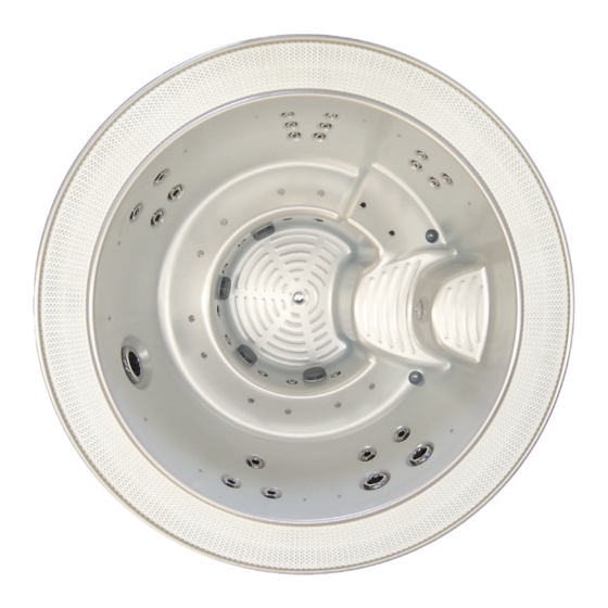
- Page 1 ACAPULCO DEEP-IN USER’S MANUAL WM00368-1 ACAPULCO DEEP IN SPA User’s manual _____________________ Version: 02.2014...
-
Page 2: Standard Specification
Standard Specification: 2400 × 2400 × 920 mm - Shell material PU reinforced acrylic (6,3 mm) - Sitting places 6 persons - Water volume 1470 l - Net weight ~ 250 kg - Heating unit 1 (3kW/230V/50Hz) - Filter grid 1 set - Support structure material Metal... -
Page 3: Warranty Letter
5 years on spa shell: WELLIS warrants the structure of the spa shell against defects in material for a period of 5 years, subject to the limitations and conditions listed in this Warranty. - Page 4 1 year on thermo cover: The thermo cover is warranted against failure due to defects in materials. 1 year on WELLIS Spa Umbrella: The factory installed WELLIS Spa Umbrellas are warranted against failure due to defects in materials. 1 year on LCD TV system: The factory installed LCD TV systems are warranted against failure due to defects in materials.
- Page 5 The water accumulates around the spa so the socket cover has to be in posses- sion of a suitable drainage. This arrangement hinders the water in collecting. 11. WELLIS Magyarország Kft. offers a limited warranty as described in the Warranty Letter. 12. Warranty claim is enforceable with this warrant letter. Irregular establishing of this warrant letter doesn`t affect to the validity of warranty obligation.
- Page 6 WELLIS Magyarország Kft. After a period of 12 months, for the purpose of assessing WELLIS Magyarország Kft. liability, all aspects covered by this Warranty will be treated on a pro-rata basis. WELLIS...
- Page 7 Magyarország Kft. or its agents will not be liable for any incidental or consequential loss or injury. Nor will WELLIS Magyarország Kft. be liable for costs associated with but not limited to building alterations or finishes and under no circumstances will be liable for greater expense than the amount paid for the product.
-
Page 8: Service Work
Service-work The announcement date of damage: _____________________________ Date of received goods/parts for repair: _____________________________ Date of the return of repaired goods/parts: _____________________________ Date of site service: _____________________________ STAMP Improved error: _____________________________ Mode of repair: _____________________________ Failed component: _____________________________ New deadline for the warranty: _____________________________ The announcement date of damage: _____________________________... - Page 9 SAFETY INSTRUCTIONS ATTENTION: PLEASE READCAREFULLY AND FOLLOW THE INSTRUCTIONS AVOIDING THE RISK OF INjURY OF CHILDREN In order to reduce the risk of injury to children, do not allow children to use this spaalone unless they are carefully supervised at all the times. Lower water temperatures arerecommended for young children.
- Page 10 INSTALLATION INSTRUCTIONS SITE PREPARATION INDOOR/bASEMENT INSTALLATION If you take it place your spa indoors, be aware of some special requirements. Water willaccumulate around the spa, so the flooring materials must provide a good grip whenwet proper drainage is essential to prevent a build-up of water around the spa. When building a new room for the spa it is recommended that a floor drain isinstalled.
- Page 11 OPERATING INSTRUCTIONS Close the drain stub and fill the spa with water After closing the drain stub, and fill up the tub with soft water to theindicated line inside of the body. If you see any leak(orflood) anywhere, stop the filling procedure until it will be fixed.
- Page 12 Remove filter grid. Unscrew filter cartridge. Clean with high pressure nozzle to remove all debris that clinging the filter. Soak filter in warm water and WELLIS Alga Shock to remove all body oils and grime. Never use chlorine to clean the filter!
- Page 13 ATTENTION! Cleaning the acrylic spa body with detergents containing alcohol or acetat is strictly FORBIDDEN! Manufacturer does not take any responsibility for damages deriving from the usage of forbidden detergents and in this case you cannot validate the guaratee for the spa body.
- Page 14 The chemical equilibrium of the water The water of the spa will be clean and clear if its chemical components are in equilibrium. pH-value: The first important indicator is the pH value of the water. pH is measured in a scale between 0-14 where 7 is the neutral value.
- Page 15 REPLACING UNDERWATER LIGHT 1. Turn off the power of the spa. 2. Remove plastic panel behind where the underwater light is situated. 3. There is a plug with two wires going into the back of the light. 4. Remove this plug by turning anticlockwise. 5.
-
Page 16: Troubleshooting
TROUbLESHOOTING Problem Probable causes Solutions Cloudy Water Dirty filters. Clean filters. Shock spa with sanitizer. Improper sanitization. Add sanitizer. Suspended particles/organic Adjust PH andl or alkalinity to recom- matter. mended range. Run jet pump(s) and clean filters. Overused water. Drain and refill the spa. Water Odor Excessive organics in water. - Page 17 Problem Probable causes Solutions Entire spa is inop- Power failure. Check power source. erative. GFCI tripped heater Reset GFCI, call for service if not reset. high-limit thermostat Disconnect power for at least thirty tripped. second to reset heater high limit. If it will not reset check for clogged filters.
-
Page 18: Tp800 Control Panel
TP800 Control Panel Spa Status Important information about spa operation can be seen quickly from the Main Screen. The most important features, including Set Temperature adjustment, can be accessed from this screen. The actual water temperature can be seen in large text and the desired, or Set Temperature, can be selected and adjusted. -
Page 19: The Main Screen
The Main Screen Navigation Navigating the entire menu structure is done with the 5 buttons on the control panel. When a text item changes to white during navigation, that indicates the item is selected for action. Operating or changing a selected item is generally done with the center or “Select” button. The only item that can be changed on the left side of the Main Screen is the Set Temperature. - Page 20 The Spa Screen and Shortcut Screen All Equipment Access The Spa Screen shows all available equipment to control, as well as other features, like Invert, in one easy-to-navigate screen. The display shows icons that are related to the equipment installed on a particular spa model, so this screen may change depending on the installation.
-
Page 21: The Settings Screen
The Settings Screen Pressing a “Button” When instructions are given to “press a button” any of the following can be done: - Navigate to the desired item on any screen. When the desired item is highlighted, press the Select Button. Programming, Etc. - Page 22 Heat Mode – Ready vs. Rest In order for the spa to heat, a pump needs to circulate water through the heater. The pump that performs this function is known as the “heater pump. ” The heater pump can be either a 2-speed pump (Pump 1) or a circulation pump. If the heater pump is a 2-Speed Pump 1, READY Mode will circulate water every 1/2 hour, using Pump 1 Low, in order to maintain a constant water temperature, heat as needed, and refresh the temperature display.
- Page 23 Fill it up! Preparation and Filling Fill the spa to its correct operating level. Be sure to open all valves and jets in the plumbing system Exit Jets 1 Jets 2 Jets 3 Circ before filling to allow as much air as possible to escape from the plumbing and the control system during the filling process.
-
Page 24: Spa Behavior
Spa behavior Pumps On the Spa Screen, select a “Jets” button once to turn the pump on or off, and to shift between low- and high-speeds if equipped. If left running, the pump will turn off after a time-out period. The pump 1 low-speed will time out after 30 minutes. The high-speed will time-out after 15 minutes. - Page 25 Spa behavior Be sure to set the Time-of-Day Setting the time-of-day is important for determining filtration times and other background features. “Set Time” will appear on the display if no time-of-day is set in the memory. On the Settings Screen, select the Time-of-Day line. On the Time-of-Day screen, simply navigate right and left to select the Hour, Minutes, AM/PM and 12/24 Hour segments.
-
Page 26: Adjusting Filtration
Adjusting Filtration Main Filtration Using the same navigation and adjustment as Setting the Time, Filter Cycles are set using a start time and a duration. Each setting can be adjusted in 15-minute increments. The panel calculates the end time and displays it automatically. Filter Cycles Filter Cycles Filter Cycle 1... -
Page 27: Additional Settings
Additional Settings Light Cycle Option If Light Cycle does not appear in the Settings Menu, the Light Timer feature is not enabled by the manufacturer. When available, the Light Timer is OFF by default. The settings can be edited the same way that Filter Cycles are edited. Light Cycle Enabled No Starts at 12:00 AM... -
Page 28: Restricting Operation
Restricting Operation The control can be restricted to prevent unwanted use or temperature adjustments. Locking the Panel prevents the controller from being used, but all automatic functions are still active. Locking the Settings allows Jets and other features to be used, but the Set Temperature and other programmed settings cannot be adjusted. - Page 29 Additional Settings Hold Mode - M037* Hold Mode is used to disable the pumps during service functions like cleaning or replacing the filter. Hold Mode will last for 1 hour unless the mode is exited manually. If spa service will require more than an hour, it may be best to simply shut down power to the spa.
- Page 30 When set to 0, no addressing is used. Use this setting for a Dolphin II or Dolphin III which is factory set for no address by default. When set between 1 and 7, the number is the address. (See the Dolphin manual for details.) Color Pressing the Select Button when Color is highlighted will cycle through 5 background colors available in the control.
- Page 31 Utilities – GFCI Test Feature The Ground Fault Circuit Interrupter (GFCI) or GFCI Status - Passed Residual Current Detector (RCD) is an important safety device and is required equipment on a hot Test tub installation. Reset Back (The GFCI Test Feature is not available on CE rated systems.) Used for verifying a proper installation Your spa may be equipped with a GFCI Protection...
-
Page 32: General Messages
General Messages Most messages and alerts will appear at the bottom Messages that can be reset of the normally used screens. will appear with a “right arrow” at the end of the message. This message Clean the filter Several alerts and messages may be displayed in a sequence. -
Page 33: Heater-Related Messages
Heater-Related Messages The water flow is low – M016 There may not be enough water flow through the heater to carry the heat away from the heating element. Heater start up will begin again after about 1 min. See “Flow Related Checks”... -
Page 34: Sensor-Related Messages
Sensor-Related Messages Sensors are out of sync – M015 The temperature sensors MAY be out of sync by 2°F or 3°F. Call for Service. Sensors are out of sync -- Call for service* – M026 The temperature sensors ARE out of sync. The fault above has been established for at least 1 hour. -
Page 35: System-Related Messages
System-Related Messages Program memory failure* – M022 At Power-Up, the system has failed the Program Checksum Test. This indicates a problem with the firmware (operation program) and requires a service call. The settings have been reset (Persistent Memory Error)* – M021 Contact your dealer or service organization if this message appears on more than one power- The clock has failed* –... -
Page 36: Reminder Messages
Reminder Messages General maintenance helps. Reminder Messages can be suppressed by using the Preferences Menu. Reminder Messages can be chosen individually by the Manufacturer. They may be disabled entirely, or there may be a limited number of reminders on a specific model. The frequency of each reminder (i.e. - Page 37 Warning! Qualified Technician Required for Service and Installation Basic Installation and Configuration Warning! GFCI or RCD Protection. Guidelines The Owner should test and reset the Use minimum 6AWG copper conductors GFCI or RCD on a regular basis to verify only. its function.
- Page 38 Sand filter user manual Filtering is just one component of the work necessary for pool cleaning and is inseparable from chemical treatment, as neither will produce the required results without the other. This is to draw your attention to the fact that, without proper chemical treatment, a fi lter cartridge in itself will not deliver the expected outcome.
- Page 39 Installation The sand filter must be placed as close to the pool as possible. Water drainage must be provided for in the motor space. Do not use steel pipes and hemp gaskets to connect the mixing valve; connect the valve only using plastic accessories and teflon tape.
- Page 40 Piping instructions of ACAPULCO spa 30mA safety relay is need to be installed!
- Page 42 Given sizes above are only information, there may be variant sizes on the grounds of the spa`s manufacturing technique.
- Page 43 BP2100 wiring diagram 3 × 16A...
- Page 44 BP2100 wiring diagram 1 × 32A...
Need help?
Do you have a question about the Round ACAPULCO DEEP-IN and is the answer not in the manual?
Questions and answers