Table of Contents

Related Manuals for Oki B83MP


Summary of Contents for Oki B83MP
- Page 1 ERVICE ANUAL B83MP B83LT B83TT B83PS LASER PRINTER OPTIONS PAPER FEED UNITS B83TT - Stand/3 x 500 Sheet Paper Drawer B83LT - Stand/MPD & 2000 Sheet Paper Drawer B83MP - Multi-Purpose Drawer OPTIONAL POWER SUPPLY UNIT B83PS - Power Supply...
-
Page 2: Table Of Contents
Belt 8 B83MP ........6 Sensor 8 Paper transport section __________________________ 8 Before installation ............6... -
Page 3: Product Outline And [2] Configuration
• For either the Stand/MPD & 2000 sheet drawer (B83LT) or the Stand/3 x 500 sheet drawer (B83TT), the optional power unit (B83PS) must be installed as well. • When the B83MP and the mail bin stacker (B83MB) or the finisher (B83F) are installed, the optional power unit (B83PS) must be installed as well. - Page 4 [3] SPECIFICATIONS 1. B83LT B83LT B83LT Paper balance 1 Tray Provided (paper empty and 3 steps) detection 2 Tray Enable (Paper empty and 6 steps Type Stand MPD & 2000 Sheet Paper Drawer (3 steps + 3 steps)) (large capacity tray + multi purpose drawer) Paper loading system To be loaded from the upper side with front Transport speed...
- Page 5 2. B83TT B83TT B83TT Tray ascent/ Ascent Within 7 seconds descent time At paper empty, required time from tray insert to Type Stand /3x500 Sheet Paper Drawer the empty detection (2 paper trays + 1 multi purpose drawer) Descent Own weight descent Transport speed To support 35-45 sheet/minute Dehumidification heater...
- Page 6 3. B83MP 4. B83PS B83MP B83PS Type Multi purpose drawer Transport speed To support 35-55 sheets/minute Input AC 100-127V / 220-240V (Two kinds) Transport alignment Center alignment Output DC 24V , 5V Paper size A3, B4, A4, A4R, B5, B5R, A5R 11"x17", 8.5"x14", 8.5"x13", 8.5"x11",...
- Page 7 [4] UNPACKING AND INSTALLATION 1. Stand/MPD & 2000 Sheet Paper b. Rotate and lower each stabilizer until they reach the floor. c. Attach the four stabilizer covers. Drawer - B83LT A. Before installation • Start installation after checking that the DATA and COMMUNICATION indicators on the operation panel are neither lit nor blinking.
- Page 8 a. Attach the rear mounting plates using a supplied screw for b. Remove the screw that secures the AC inlet cover and each. then remove the AC inlet cover. c. Configure the AC inlet cover as shown in the illustration. Rear mounting plate Cut out.
-
Page 9: Before Installation
optional power supply harness are arranged as shown in 10. Connect the AC cord of the power supply unit to the the illustration. outlet connector of the main unit of the printer at the location shown in the illustration. d. Fix the harness securely to the wire saddle. Screw Optional power supply harness... - Page 10 2. Stabilizer install and adjustment: a. Attach the rear mounting plates using a supplied screw for each. a. Insert the central bar to the stand/paper drawer. Rear mounting plate Note: Be sure to attach the left adjuster first to prevent overturning. b.
- Page 11 a. Remove the four screws that fix the rear cabinet and then b. Connect the optional power supply harness connector to remove the rear cabinet. CN11 (red connector) of the PCU PWB of the main unit of the printer. Connector CN11 Rear cabinet c.
-
Page 12: B83Mp
3. B83MP the rear cabinet and attach the rear cabinet to the stand/ paper drawer. A. Before installation • When installing B83MP, if you install a finisher or mail- bin stacker together, a power supply unit (B83PS) is needed. Rear cabinet b. - Page 13 drawer so that the front side and the left side of the main c. Reattach the paper tray of the main unit of the printer. unit are aligned to those of the multi purpose drawer. Front side Rear side 4. Connect the harness to the main unit of the printer. a.
-
Page 14: Power Supply - B83Ps
• Fix the harness securely to the wire saddle. 3. Remove the screw that secures the AC inlet cover and remove the AC inlet cover. Configure the AC inlet cover Screw as shown in the illustration. Cut-out AC inlet cover Harness cover Wire saddle 4. - Page 15 wiring of the optional power supply harness has been 8. Insert the power plug of the printer to the outlet. handled as shown in the illustration. Then, turn the main switch located on the front of the printer to "ON." Screw Optional power supply harness...
-
Page 16: External Views And Internal Structures
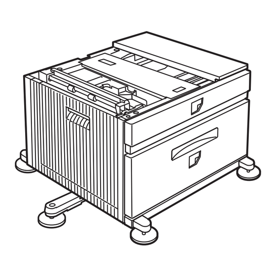
[5] EXTERNAL VIEWS AND INTERNAL STRUCTURES 1. External view B83TT B83LT B83MP Multi-purpose tray (No. 2 tray) No. 3 tray No. 4 tray Large capacity tray Desk left door 2. Internal structure A. B83LT - Stand/MPD & 2000 Sheet Paper Drawer 1.TPFD1... -
Page 17: B83Tt - Stand/3X500 Sheet Paper Drawer
Desk tray 2 take-up roller Desk tray 2 Multipurpose tray separation roller Desk tray 3 take-up roller Desk tray 3 C. B83MP - Multi-Purpose Drawer 1.MCPPD 3 4 5 Multipurpose tray paper transport sensor (MCPPD) Multipurpose tray paper feed roller... -
Page 18: Pwb - Print Wire Board, Sensor
3. PWB - Print Wire Board, sensor A. B83LT 21.MP tray rear edge size PWB 6.MCLUD 5.TPFD3 8.MCSS2 7.MCSS1 4.MCSPD 10.MCSS4 3.TDRS 9.MCSS3 2.TSPD1 1.TPFD2 11.TTSD 12.TLUD2 13.TPED2 14.TSPD2 19.TLUD1 15.MCPED 20.TPED1 16.TPFD1 17.MCPWS Code Name Function Active condition Remark TPFD2 Tandem tray paper transport sensor 2 Tandem tray paper transport detection... -
Page 19: B83Tt
B. B83TT 4.MCLUD 28.MP tray rear edge size PWB 5.MCPED 7.MCSS2 6.MCSS1 2.MCSPD 9.MCSS4 1.DDRS 8.MCSS3 29.No. 3 tray rear edge size PWB 10.DCSS11 11.DCSS12 27.DSPD1 13.DCSS14 26.DLUD1 12.DCSS13 30.No. 4 tray rear edge size PWB 25.DSPD2 14.DCSS21 15.DCSS22 18.DPFD1 24.MCPWS 17.DCSS24 23.DLUD2... -
Page 20: B83Mp
C. B83MP 12.MP tray rear edge size PWB 6.MCSS2 5.MCSS1 4.MCLUD 3.MCSPD 8.MCSS4 7.MCSS3 1.MCDRS 9.MCPED 10.MCPPD 11.MCPWS Active Code Name Function Remark condition MCDRS MP door open / close sensor MP left door open / close detection H : Door closed... -
Page 21: Motor, Clutch
4. Motor, clutch A. B83LT 7.TPCL2 8.TLUM2 6.TMM 5.MCPCL 4.MCLUM 3.TPFCL 2.TPCL1 1.TLUM1 Code Name Function Remark TLUM1 Tandem tray 1 lift-up motor Tandem tray 1 lift-up TPCL1 Tandem tray 1 paper feed clutch Clutch for paper feed from tandem tray 1 TPFCL LCC transport clutch Clutch for transport from LCC desk... - Page 22 No. 3 tray desk paper transport DPCL2 Desk 2 tray paper feed clutch Clutch for paper feed from desk tray 2 DPCL1 Desk 1 tray paper feed clutch Clutch for paper feed from desk tray 1 C. B83MP 4.MCM 3.MCPCL 2.MCLUM 1.MCFCL Code Name...
-
Page 23: B83Lt
MENU 1. Press the key repeatedly until "CUSTOM SETTINGS" appear in the message display. position adjustment (B83LT/B83TT/ B83MP) A. Adjustment procedures in diag (Printer model) MENU 1. Turn the main switch on while pressing the and the key of the operation panel of the main unit of the printer. - Page 24 8. Select the paper type that has been set in the tray. Press the [ ] or [ ] key repeatedly until the paper type that has been set appears. PLAIN 9. Press the key. 10. Ensure that the desired paper size is selected. Press the [ ] or [ ] key repeatedly until the desired...
-
Page 25: Disassembly And Assembly, Maintenance
[7] DISASSEMBLY AND ASSEMBLY, MAINTENANCE 1. Maintenance System Table Check (Clean, replace, or adjust as necessary.) Clean Replace Adjust Lubricate Move position When Unit name Part name 100K 150K 200K 250K 300K 350K 400K Remark calling Paper feed Paper feed rollers separation section Torque limiter Transport section... -
Page 26: Roller/Torque Limiter
3. Remove the multi-purpose paper feed unit. 4. After removing the roller, remove the torque limiter. • When installing the torque limiter, check to insure that the pin is fully inserted into the torque limiter groove. Belt Name Job item Cycle Roller/Torque limiter Belts... -
Page 27: Sensor
Sensor 2. Remove the left door. Name Job item Cycle Sensors Check 3. Remove the tandem paper feed unit. Roller/Torque limiter Name Job item Cycle Tandem tray paper feed section Rollers Clean Check Paper feed unit disassembly Replace 80K or 2 years 1. -
Page 28: Belt
• Tandem tray 2 • Tandem tray 2 Sensor Name Job item Cycle Sensors Check Note: When installing the roller, check to insure that the hook is securely engaged in the groove. Note: When installing the torque limiter, check to insure that the pin is fully inserted into the torque limiter groove. -
Page 29: Paper Transport Section
Paper transport section 1. Remove the left door. Belt Name Job item Cycle Gears Lubricate Belts Check 240K Transport roller/Roller Name Job item Cycle Transport rollers Clean Rollers Clean Drive section 1. Remove the rear cabinet. Multi-purpose tray drive section 1. -
Page 30: Tandem Tray Drive Section
Others 2. Gear/Belt 1. Remove the rear cabinet. Name Job item Cycle Gears Lubricate Belts Check 240K Tandem tray drive section 2. Remove the control PWB and the sensors. 1. Remove the tandem tray drive section. Name Job item Cycle Sensors Check 2. -
Page 31: B83Tt
B. B83TT Roller/Torque limiter Name Job item Cycle Paper feed section Rollers Clean Paper feed unit disassembly Check 1. Extract the multi-purpose tray by pulling out the right side Replace 80K or 2 years of the tray and then pulling out the left side. Torque limiter Check 240K... -
Page 32: Belt
• When installing the torque limiter, check to insure that the pin is fully inserted into the torque limiter groove. Belt Name Job item Cycle Belts Check 240K Paper transport section 1. Remove the left door. Sensor Transport roller/Roller Name Job item Cycle Name... -
Page 33: Drive Section
Tandem tray drive section Drive section 1. Remove the tandem tray drive section. 1. Remove the rear cabinet. Multi-purpose tray drive section 2. Gear/Belt 1. Remove the multi-purpose tray drive section. Name Job item Cycle Gears Lubricate Belts Check 240K 2. -
Page 34: Others
Others C. B83MP 1. Remove the rear cabinet. Paper feed section Paper feed unit disassembly 1. Pull out the multi-purpose tray by pulling out the right side of the tray, and then pull out the left side. 2. Remove the control PWB. -
Page 35: Belt
Sensor 3. Disengage the roller hook, and remove the roller. Name Job item Cycle Sensors Check * When installing the roller, check to insure that the hook is securely engaged in the groove. 4. After removing the roller, remove the torque limiter. * When installing the torque limiter, check to insure that the pin is fully inserted into the torque limiter groove. -
Page 36: Drive Section
Drive section 1. Remove the rear cabinet. 2. Remove the tray drive section. 3. Gear/Belt Name Job item Cycle Gears Lubricate Belts Check 240K Note: The numbers in illustrations reflect the sequence required for disassembly/assembly. B8300n Paper Feeder Products - Disassembly and Assembly, Maintenance 7-12...
Need help?
Do you have a question about the B83MP and is the answer not in the manual?
Questions and answers