Table of Contents
Advertisement
Quick Links
Model:
Comfort Fresh Air 150C
Comfort Fresh Air 250C
Comfort Fresh Air 300C
Comfort Fresh Air 500C
Comfort Fresh Air 650C
Comfort Fresh Air 800C
Comfort Fresh Air 1000C
Comfort Fresh Air 1500C
Comfort Fresh Air 2000C
Thanks for supporting the Energy Recovery Ventilator from Holtop Group.
※
Please read this manual carefully before using the equipment. For safety precautions, please read
carefully before construction or use, and use the equipment safely. Keep the manual properly after
reading, so that user can read it when necessary.
※
Please ensure that this manual is handed over to the end user.
Energy Recovery Ventilator
Standard:JISB 8628-2017/8639-2017
Technical Manual
Advertisement
Table of Contents

Subscribe to Our Youtube Channel
Related Manuals for HOLTOP Comfort Fresh Air 150C


Summary of Contents for HOLTOP Comfort Fresh Air 150C
- Page 1 Comfort Fresh Air 1000C Comfort Fresh Air 1500C Comfort Fresh Air 2000C Thanks for supporting the Energy Recovery Ventilator from Holtop Group. ※ Please read this manual carefully before using the equipment. For safety precautions, please read carefully before construction or use, and use the equipment safely. Keep the manual properly after reading, so that user can read it when necessary.
-
Page 2: Table Of Contents
Contents 1、Safety precautions -------------------------------------1-2 2、Unit Description-----------------------------——--------3-5 3、Installation Considerations------------------------------6-7 4、Installation Method --------------------------------------8 5、Connecting the ducts -----------------------------------9-10 6、Electrical Installation -----------------------------------11-12 7、Precautions for Use-------------------------------------13 8、Commissioning------------------------------------------13 9、Operation Method---------------------------------------14-22 10、Communication protocol------------------------------23-24 11、Maintenance--------------------------------------------25 12、Failure diagnose---------------------------------------26... -
Page 3: 1、Safety Precautions
Safety precautions Packing list: Pls kindly check after unpacking: one ventilator, one controller and one set of attached data. 1、Safety precautions The following signs indicate that death or serious injury may be caused by failure to heed the precautions described below. Safety attentions Please read the following safety instructions before installation. - Page 4 Safety precautions Power cable and wires must be installed by To avoid condensation, insulation should be a qualified electrical engineer. Improper fitted to fresh air ducts. Other ducting may connection can cause over heating. Fire and also require insulation depending on dew loss of efficiency.
-
Page 5: 2、Unit Description
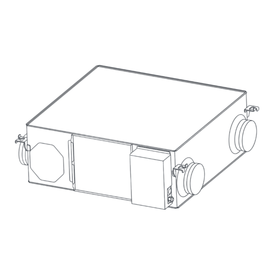
Unit Description 2 Unit Description 2.1 Principle and function Energy Recovery ventilator is a kind of ventilator equipment for air energy recovery. It is composed of supply air fan, exhaust fan, total heat exchanger, pri- mary filter of original air, primary filter of return air, etc. Energy Recovery ventilator function: the purified fresh air is continuously transported to the room through the air supply outlet, and the indoor dirty air is discharged at the same time, so as to improve the indoor air quality. - Page 6 Dimensions 2.3 Dimensions Models CFA 150C to CFA 1000C Nominal diameter Model Diameter CFA 150C Φ100 CFA 250C Φ150 CFA 350C Φ150 CFA 500C Φ200 CFA 650C Φ200 CFA 800C Φ250 CFA 1000C Φ250 Ceiling suspension Duct connecting Dimensions Duct pitch fixture pitch flange Weight...
- Page 7 Dimensions 2.3 Dimensions Models CFA 1500C to CFA 2000C Ceiling suspension fix- Dimensions Duct pitch ture pitch Weight (Kg) Model CFA 1500C 1144 1004 1182 CFA 2000C 1144 1231 1182 1213 2.4 Specifications Static pres- Air volume Exchange efficiency (%) sure Running Input...
-
Page 8: 3、Installation Considerations
Installation Considerations Description: *The above values apply during ventilation when the fan speed is set to Fan speed 10at the rating pres- sure loss and 230 V / 50 Hz. *For the specifications at the other frequency or voltages, contact your dealer. according to Japan Industrial Standard (JIS B 8628), therefore Q-H curves are measured by *Poducts chamber method . - Page 9 Installation Considerations 3.3 Unit must not be installed close to boiler flues. 3.4 Following phenomenon should be avoided in the ducting installation. Multiple reducers/ crimped duct Serve bends Multiple direction changes 3.5 Exessive use of flex-duct and long flex-duct runs should be avoided. 3.6 Fire dampers must be fitted as per national and local fire regulations.
-
Page 10: 4、Installation Method
Installation Method 4 Installation method 4.1 Preparing the anchor bolts Mount the washers (outer diameter of>21 mm for M10, >24mm for M12) and nuts onto the pre-recessed anchor bolts (M10 or M12), as shown in the figure below. When using (customer-prepared) vibration isolation rubber, there is a possibility of this causing a decrease in strength, so we recommend the following type of construction. -
Page 11: 5、Connecting The Ducts
Connecting the ducts 螺母 垫圈 Gasket Suspending screw pole 天花板吊装螺杆 吊装部件 Suspending Part 垫圈 Gasket (Φ 10-Φ 12) 螺母 5 Connecting the ducts 5.1 Fasten the duct securely to duct connecting flange ,and aluminium tape(field supply) around the joints so that there is no qir leakage. 5.2 Suspend the ducts from the ceiling so that their weight will not be applied to the unit. - Page 12 Connecting the ducts Standard installation examples Suspending Pole Outside Fresh Air Duct Supply Duct OA(optional) EA(optional) Supply Air Return Duct Return Air insulation Exhaust Duct CFA 150C to CFA 1000C Suspending Pole Supply Duct Outside Fresh Air Duct Supply Air Return Air Exhaust Duct Return Duct...
-
Page 13: 6、Electrical Installation
Electrical Installation 6 Electrical Installation Power must be isolated during installation and before maintenance to avoid injury by electric shock. The specifications of cables must strictly match the requirements, otherwise it may cause performance fail- ure and danger of electric shock or fire. Power supply is AC220-240V/50HZ/1 Phase. - Page 14 Electrical Installation Wiring Diagrams pressure Control bypass switch switch panel RS485 fire siganl Humidity Disply EA FAN RA temperature SA temperature OA temperature SA FAN Boot signal WIFI error signal run signal R-Heat P-Heat Bypass monitor Ground wire reactance AC 220V~240V 50Hz EA FAN SA FAN...
-
Page 15: 7、Precautions For Use
Precautions for Use and Commissioning 7 Precautions for Use Loose or incorrect wiring connection can Don’t put fingers or objects into vents of cause explosion or fire when the unit starts fresh air or exhaust air supply. Injury may to work. Use only rated power voltage. be caused by the rotation of the impeller. -
Page 16: 9、Operation Method
Precautions for Use 9、 Controller Instructions(HDK-CK22C) Name ON/OFF Button MODE Button UP Button DOWN Button SET Button Supply Air Fan on/off Exhaust Air Fan on/off Bypass mode on/off Heat exchange mode on/off Pre heating Heating Communication PM2.5 TOVC Clock Timed power on/off Time Time period Automatic Mode... - Page 17 Precautions for Use 4、Operation Mode: When it is turned on, the screen display is heat exchange mode, user can press the MODE button to switch the operating mode of the device. The sequence is heat exchange mode, bypass mode, auto- matic mode (four periods mode), and sleep mode, is switched cyclically.
- Page 18 Precautions for Use ④ Sleep Mode: In the sleep mode, the supply air fan and exhaust air fan are running in speed 1, and the screen be- comes darker and standby after 30s. When the automatic bypass is not turned on (or the bypass mode opening conditions are not reached), the icon of the sleep mode and the heat exchange mode are long bright.
- Page 19 Precautions for Use steps and completed set the timed on/off, it can be exited automatically without operation for 15, or the short press MODE button to exit. 8.Setting positive and negative pressure User can set the speed of the supply air and exhaust air separately. If the positive pressure is need- ed, the speed of supply air should be higher than the speed of exhaust air;...
- Page 20 Precautions for Use 11. Intelligent air volume compensation (PS: only applicable to the highest speed): During the long-term operation of the equipment, the filter screen will accumulate dust and gradu- ally block, which will lead to the increase of equipment resistance and the decrease of air volume. In order to make up for the air volume loss, the air volume will be increased along with the regular pres- surization of the supply and exhaust fans (the pressurization percentage can be set in the parameter item).
- Page 21 Precautions for Use 16. One button high speed Application: In the kitchen or bathroom, the equipment can be turned on remotely through the rocker switch. One remote rocker switch control interface is reserved on the mainboard. When the interface is connected, the supply fan and exhaust fan operate under the highest speed.
- Page 22 Precautions for Use 21. Temperature adjustment function Under the parameter item, press the "△" and "▽" button to set the electric heating startup temper- ature, the range is 16-30. If the SA temperature is higher than the set temperature, both electric heat- ing stops, and the preheating and heating displays are both extinguished.
- Page 23 Precautions for Use EA fan control voltage adjust- SA fan control voltage adjustment interface ment interface After entering the voltage setting interface, first enter the control voltage setting interface of the air supply motor first. At this time, the icon flashes.
- Page 24 Precautions for Use Contents Range Default Unit Centralized Control 1-99 Address Power to auto restart 0 - invalid, 1-valid Auto Bypass 0 - invalid, 1-valid Bypass opening tempera- 5-30 ℃ ture X Temperature Deviation Y 2-15 ℃ Electric Heating 0 - invalid, 1-valid Temperature Electric 16-30...
-
Page 25: 10、Communication Protocol
Precautions for Use 10 Centralized control Modbus-RTU Parameters: baud rate:9600, no check,1 digit stop position, 8 bit data. Support Function code: Read 03, write 06 Communication data interval >=200ms Register Read Writ Value Function description Remark address able able range 0(0x0000) on-off state , 0 - off 1 - on This parameter can-... - Page 26 Precautions for Use Register Read Writ Value Function description Remark address able able range 13(0x000d) 0-5000 Co2 Data O can not be written 14(0x000e) Electric Heating, 1-on, 0-off 15(0x000f) 16-30 Setting electric heating temperature 16(0x0010) -30~+99 Supply Air Temperature 17(0x0011) -30~+99 Return Air Temperature 18(0x0012)
-
Page 27: 11、Maintenance
Maintenance 11 Maintenance Before maintaining the system, cut off the power supply. Maintain the device after it stops completely to avoid damage. Energy Recovery Ventilation (purification) needs regular cleaning and maintenance. If it is not cleaned and maintained correctly and reg- ularly, its filtration efficiency and heat exchanger efficiency will be greatly reduced. -
Page 28: 12、Failure Diagnose
Failure diagnose 12 Failure diagnose User can use the unit after trial operation. Before contacting us, you can make self trouble shooting fol- lowing below chart in case of any failure. Phenomenon Possible reason Solutions The airflow volumes both in- door and outdoor vents drop Dust and dirt blocking the filter Replace or clean the filter... - Page 29 QD5003A10F04...
Need help?
Do you have a question about the Comfort Fresh Air 150C and is the answer not in the manual?
Questions and answers