
Subscribe to Our Youtube Channel
Related Manuals for baxter Helion


Summary of Contents for baxter Helion
- Page 1 Instructions for use Helion Video Management System Read the instructions for use carefully before using the ENGLISH product and keep them safe for future reference. en-US...
- Page 2 This page is intentionally blank.
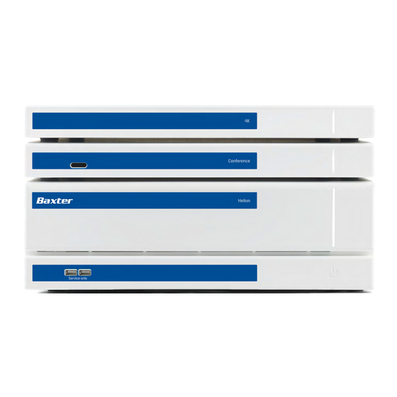
- Page 3 Helion Main Unit AR VR401111-2 Helion Main Unit ARD VR401111-2D Helion Main Unit ARSD VR401111-2DT Helion Main Unit ARS VR401111-2T Helion Main Unit SSD R VR401111-3 Helion 4K VR401112 Helion 4K Plus VR401113 Helion Conference CM401326 80028000_030_F – 773607 – 2024-05-28...
- Page 4 Helion Optional sales items for the Helion video management system. Not all products are available in all countries. Product designation Helion Rack (115V) AC500920K Helion Rack (230V) AC500920K-2 Helion Rack (115V) - Permanent Install. AC500920K-3 Auxiliary Rack (115V) - Plug&Play Install.
- Page 5 Helion PREFACE All rights reserved. No part of this publication may be copied, distributed, translated into other languages or transmitted by any electronic or mechanical means, including photocopying, recording or any other storage and retrieval system, for any purpose other than the buyer’s personal use, without the express written permission of the manufacturer.
- Page 6 Helion This page is intentionally blank. 80028000_030_F – 773607 – 2024-05-28...
-
Page 7: Table Of Contents
Combination with other Baxter products ........ - Page 8 Contents “Video Routing” function ............40 5.3.1 Live Preview .
-
Page 9: General Preliminary Information
General preliminary information General preliminary information Operator’s responsibility The instructions for use of Helion Video Management System are intended for operators who are trained and authorized to handle it. The management of the medical site is responsible for the training of staff on the use of the medical device. -
Page 10: Personnel Qualifications
User Person suitably trained or who, thanks to their professional qualification, is authorized to operate and use the Helion Video Management System as required. They are responsible for the correct and safe operation of the system and ensure that it is used solely for the intended purpose. - Page 11 General preliminary information Symbol Description Symbol used to indicate the date of manufacture. Symbol used to identify the manufacturer’s name. Barred bin: this product must not be disposed of as municipal mixed waste; collect separately. Symbol used to indicate the Videomed S.r.l. material number. Symbol used to indicate the serial number.
-
Page 12: Product Certification
General preliminary information Product certification The Helion video management system is a Class I medical device according to Regulation 2017/745/EU concerning medical devices, and is compliant with the version of the regulation currently in force at the time of product sale. Videomed S.r.l. -
Page 13: Safety Information
DANGER ELECTRIC SHOCK FROM INCORRECT POWER CONNECTION PROCEDURE! The Helion system must be powered and earthed from the same electrical panel that powers the operating room. All equipment connected to the Helion system must also be powered and earthed from the same electrical panel that powers the operating room. -
Page 14: Security Considerations
MEASUREMENT OF DISPERSAL CURRENTS! It is necessary to measure the leakage currents with the circuits downstream of the Helion system open. Otherwise, the leakage currents of these circuits will be added to those of the Helion system. CAUTION It is absolutely forbidden to remove the device labels and/or replace them with other labels. - Page 15 Updates and patches: – Installation of updates and patches should be done by a trained service technician authorized by Baxter following the installation directions. – Do not initiate an update during product usage.
-
Page 16: Privacy Considerations
Privacy features in the product: The Product has features that help protect patient data. – Local storage: Data is only temporarily stored on the Helion system, which is hosted on-premises at the customer’s facility and is then transferred to the customer’s system and servers. - Page 17 Safety information – User authentication: To ensure that only authorized users can access patient data, it is necessary to enable user authentication for the product. The Authentication Application is designed to authenticate only authorized users by requiring them to prove their identity through a secure web application. Additionally, the system maintains a record of user activity and permissions to ensure compliance with regulations and policies.
-
Page 18: Useful Life Of The System
• Apply liquid to the cleaning cloth. NOTICE Risk of material damage Do not clean the Helion unit’s rear connector panel, or any of its connectors or buttons. This may cause damage to the connectors, buttons, and internal electronics. • Call Baxter service. -
Page 19: Cleaning Agents
Safety information 2.5.1 Cleaning agents When selecting the cleaning agents, ensure that they do not contain the following components: – Organic, mineral, and oxidizing acids – Bases – Organic solvents (e.g., ether, ketones, benzines) – Halogens (chlorine, iodine, bromine) – Aromatic/halogenated hydrocarbons –... -
Page 20: System Description
– In the offices of physicians in private practice and other operating room-like environments, when the video conference function is used. – Note: If Helion is placed on a boom shelf, keep a distance of 1.5 m or more to the surgical area during surgery. Normal use –... -
Page 21: Contraindications
System description – Exchange of information by video conference with the operating room by sharing images and videos with the world outside the room in high resolution – Regular maintenance of the MD in accordance with the defined maintenance intervals by qualified service technicians –... -
Page 22: Use Associated With Other Devices
2072249 (in combination with Trulight) 3.10.2 Combination with products of other manufacturers The Helion Video Management System can be combined with devices from other manufacturers. In the patient environment, only install devices approved in accordance with standard IEC 60601-1. Outside the patient environment, devices approved in accordance with standards IEC 62368-1 are also allowed. -
Page 23: Obligations And Prohibitions
System description It is also possible to use a medical FHD Touchscreen Monitor that is not included in the catalogue. Please contact Technical Customer Service (www.hillrom.com) for compatibility information. 3.11 Obligations and prohibitions The management of the medical site is responsible for training staff on the use of the medical device. - Page 24 System description Main Unit - Technical Specs Enclosure IP20 Environmental Operating temperature: +10/+40 °C conditions Operating relative humidity range: 30% to 75% Operating atmospheric pressure range: 54.0 kPa to 106.0 kPa Storage temperature: -40/+70 °C Storage relative humidity range: 10% to 100% including condensation Storage atmospheric pressure range: 50.0 kPa to 106.0 kPa Max Operation Altitude 5000 mt...
- Page 25 System description Conference Unit - Technical Specs Protection Short circuit protection Overload protection Overcurrent protection Overvoltage protection Insulation Voltage Input / Output 4000 V AC Input / FG 1500 V AC Environmental Operating temperature: +10/+40 °C conditions Operating relative humidity range: 30% to 75% Operating atmospheric pressure range: 54.0 kPa to 106.0 kPa Storage temperature: -40/+70 °C Storage relative humidity range: 10% to 100% including...
- Page 26 System description 4K Unit - Technical Specs Environmental Operating temperature: +10/+40 °C conditions Operating relative humidity range: 30% to 75% Operating atmospheric pressure range: 54.0 kPa to 106.0 kPa Storage temperature: -40/+70 °C Storage relative humidity range: 10% to 100% including condensation Storage atmospheric pressure range: 50.0 kPa to 106.0 kPa Max Operation Altitude 5000 mt...
- Page 27 System description Rack Unit (optional) - Technical Specs Dimensions 800 x 600 x 757 mm Color RAL 7016 puckered Environmental Operating temperature: +10/+40 °C conditions Operating relative humidity range: 30% to 75% Operating atmospheric pressure range: 70.0 kPa to 106.0 kPa Storage temperature: -40/+70 °C Storage relative humidity range: 10% to 100% including condensation...
-
Page 28: Measurement And Weight Layout
System description 3.13 Measurement and weight layout Main Unit Dimensions 133 x 430 x 450 mm Unit Weight 13.5 kg Rack Dimensions (optional) Rack Brackets (optional) 80028000_030_F – 773607 – 2024-05-28... - Page 29 System description Conference Unit Dimensions 44 x 430 x 450 mm Unit Weight 8 kg Rack Dimensions (optional) Rack Brackets (optional) 80028000_030_F – 773607 – 2024-05-28...
- Page 30 System description 4K Unit Dimensions 44 x 430 x 450 mm Unit Weight 5.5 kg Rack Dimensions (optional) Rack Brackets (optional) 80028000_030_F – 773607 – 2024-05-28...
- Page 31 System description 4K Plus Unit Dimensions 44 x 430 x 450 mm Unit Weight 5.5 kg Rack Dimensions (optional) Rack Brackets (optional) 80028000_030_F – 773607 – 2024-05-28...
- Page 32 System description Rack Unit Dimensions 800 x 600 x 757 mm Unit Weight 64 kg adjustable foot height 80028000_030_F – 773607 – 2024-05-28...
-
Page 33: System Components
System description 3.14 System components The Helion Video Management System has a modular structure composed of 3 operating units that can be used simultaneously. The only unit that can operate independently is the Main Unit. 4K Unit or 4K Plus Unit... -
Page 34: Conference Unit
The connection cables are supplied by Videomed S.r.l. 3.14.5 Control software The User Interface of Helion Video Management System allows each functional unit to be controlled and managed. There is a lower selection bar (always visible) that allows the software sections to be uniquely identified according to the function performed. - Page 35 VIDEO CONFERENCE function. This function allows two-way audio/ video communication. The Helion Video Management System also assures control and management of the main devices installed in the operating room: – PTZ Roomcam – surgical lights with surgical video camera The complete functions present in the Control Software are described in detail in the “User Interface”...
-
Page 36: Operation
Operation Operation First system start The Helion Video Management System is delivered to the operator by the authorized installer technical personnel from Videomed S.r.l. System commissioning requires for the operator to be adequately trained on the functional and visual controls, on the adjustments and calibration, on system cleaning and maintenance, and on the applicable user instructions. -
Page 37: Connection To The Sources
It is recommended to use forced shutdown only in case of an emergency, as this procedure may cause data loss. In case it is necessary to interrupt communication between Helion and any controlled devices, proceed to shut down the system. -
Page 38: System Startup/Shutdown With Remote Button
Operation System startup/shutdown with remote button The Helion Video Management System allows the units to be restarted via a remote on/off button installed inside the operating room (typically on a pendant panel or wall unit). Thanks to this solution, the operator can manage the entire video management system without having to access the Technical rack. -
Page 39: User Interface
User Interface User Interface General description of the user interface The user interface is divided as follows: Element Description STATUS BAR Bar containing important information such as the patient’s name and the number of recorded media related to them. Information such as the date, time, and a dashboard showing the status of the recording, the video conference, the streaming and the advanced modes “Privacy Mode”, “Do Not Disturb”, and “Lecture Mode”... -
Page 40: Control Touchscreen
User Interface Control touchscreen The control screen is a high-resolution touchscreen. The user interface buttons are activated with a brief touch of the finger, or by swiping. The control screen has its own setup menu from which the monitor settings can be accessed: –... -
Page 41: Live Preview
User Interface list of sources connected list of monitors enabled To send a video signal to a monitor, drag the relevant image from the Source List [A] available and drop it into one of the enabled monitors [B], by using the Drag&Drop system. The Preview of the video signal sent will be displayed in the relative monitor icon and updated periodically. - Page 42 User Interface Step Image Press the icon in the corresponding Preview. An enlarged version of the selected image is displayed. Press to return to the Video Routing section standard view. The following icons are present in the Live Preview window: Icon Function Starts/stops recording of the displayed signal.
-
Page 43: Quick Access - Recording
User Interface Icon Function Starts/stops video signal streaming. Activates the fullscreen display function, without latency, of the selected source (function available only on some touchscreen monitor models). It is not possible to start recording if a reference patient is not present. -
Page 44: Quick Access - Streaming
User Interface Step Image In systems where the dual recording channel is enabled, this function can be activated on two sources at the same time. 5.3.3 Quick Access - Streaming To activate the streaming session, proceed as follows: Step Image Press the box of a Preview to start streaming the signal... -
Page 45: Ptz Camera Control
User Interface 5.3.4 PTZ camera control The Live Preview function, if activated on a controllable camera signal, will allow access to its movement controls. 5.3.4.1 Roomcam zoom adjustment To adjust the zoom of the Roomcam, proceed as follows: Step Image to adjust the zoom and obtain the desired image (view). -
Page 46: Saving A Camera Setting (Preset)
User Interface 5.3.4.3 Saving a camera setting (Preset) To save a specific video camera setting (Preset), proceed as follows: Step Image After adjusting the video camera to the desired position, press Give it a name and press confirm. The new named Preset will appear on the list on the side. -
Page 47: Deleting A Camera Setting (Preset)
User Interface 5.3.4.4 Deleting a camera setting (Preset) To delete a video camera setting from the Preset list, proceed as follows: Step Image Press Press and hold the button until it is deleted. 80028000_030_F – 773607 – 2024-05-28... -
Page 48: Enabling A Camera Setting (Preset)
User Interface 5.3.4.5 Enabling a camera setting (Preset) To activate a video camera Preset, proceed as follows: Step Image Press the desired Preset in the list. Press to confirm the Preset selection. “Recording” function The Recording function enables capture snapshots and video recording from the signals connected to the system. -
Page 49: Image Data Post-Processing
User Interface source list view of the two recording channels list of snapshots and videos stored The user may view and reproduce any material stored during the surgical activity (images and video) at any time by pressing the icon . This way, a list will appear on the screen containing all previews of stored files, which can then be reproduced and processed by using the functions described in paragraph “Snapshot and video playback”. -
Page 50: Selecting The Signals To Be Recorded
User Interface 5.4.2 Selecting the signals to be recorded Drag the source you wish to record a video or capture snapshots from into the Recording Channel box, where you will get a Live Preview of the signal and the basic and advanced recording functions will be enabled. -
Page 51: Recording
User Interface 5.4.3 Recording To perform the recording from the Recording function, proceed as follows: Step Image Press the box on a Recording Channel to start recording a signal. When recording is in progress, the button is red in the Recording Channel selected. -
Page 52: Snapshot And Video Playback
User Interface 5.4.4 Snapshot and video playback To play snapshots and videos, proceed as follows: Step Image Press and then simply press if the printing function is not enabled) to view all images and videos related to the selected patient. Press the icon to enlarge the selected media item. -
Page 53: Crop Video
User Interface 5.4.5 Crop video To cut the videos, proceed as follows: Step Image Press and then simply press if the printing function is not enabled) to view all images and videos related to the selected patient. Press the icon to enlarge the selected media item. -
Page 54: Export Images And Videos
User Interface Step Image Once the cutting points are determined, extract the cropped video by pressing A new video appears in the photo/video list of the same patient. 5.4.6 Export images and videos Press and then (or simply press if the printing function is not enabled) to access the folder for exporting images and videos of the selected patient. - Page 55 User Interface To export, proceed as follows: Step Image Select the export destination. This must be done for the images or videos to be exported. Pressing (on the right side of the screen) to send the files to the selected destinations.
-
Page 56: Delete Images And Videos
User Interface 5.4.7 Delete images and videos Press and then (or simply press if the printing function is not enabled) to access the folder for storing images and videos of the selected patient. To delete images and videos, proceed as follows: Step Image Select the videos or images you... -
Page 57: Printing Function
User Interface 5.4.8 Printing function The Printing function allows to print images of the selected patient directly from the Helion UI. Click on icon and then on icon to access the printing section. A screen with all the captured images is displayed, where you can select the ones to be printed and the layout to be used. -
Page 58: Video Conference" Function
The web user experience vary according to the browser used. This function is available only after the selected printer(s) have been installed and configured on Helion by qualified service personnel. “Video Conference” function The Video Conference function allows video conferencing in two-... - Page 59 User Interface – external participants who are in other locations can connect to the system online The following modes are available: Mode Description Preview of the Enables viewing of one, or in the case of multi-channel video transmission channel conferencing, both connected transmission channels. Image or video sources All connected sources are displayed in the input signal bar.
-
Page 60: Selecting The Signals To Be Sent By Video Conference
User Interface 5.5.1 Selecting the signals to be sent by video conference From the Source List, drag the source you wish to send in video conference into the Primary Channel (or Secondary Channel) box. 5.5.2 Removing the signals to be sent by video conference Press one of the boxes related to the primary and/or secondary video conference channel and then the icon that displays... -
Page 61: Call Recipient Selection
User Interface 5.5.3 Call recipient selection To select the recipient of the call, press the respective icon (depending on the mode) on the right side of the screen. The icons are described below: Icon Description Image Select a name from the contact list. -
Page 62: Call Start
5.5.5 Call H.323/SIP recipient The following instructions provide the steps required to: – Access the Helion system address book – Call into an H.323/SIP meeting through the Helion system Step Image On a PC with Helion network access, open a modern web... -
Page 63: On Air Lamp
Note: You can mark a contact as “Favorite” to make it appear at the top of the list. Favorites appear in alphabetical order. Click Log into the Helion System User Interface. Navigate to the Video Conference tab and review saved contacts in the address... -
Page 64: Patient Data Management
Access the Audio setup screens. Access the management screen of the operating lights in the operating room. This function can only be used if associated Baxter devices are present. Access the control screen of the lights in the operating room. -
Page 65: Selecting A Patient From The List
User Interface 5.7.1.1 Selecting a patient from the list To select a patient already in the list, proceed as follows: Step Image Select the patient. Press to confirm the selection. 5.7.1.2 Entering a new patient To enter a new patient, proceed as follows: Step Image Select the... -
Page 66: Entering An Emergency Patient
User Interface Step Image Enter the data for the new patient. Fields marked with * are mandatory. Once the mandatory data have been filled in, save the new patient by pressing cancel the insertion with 5.7.1.3 Entering an emergency patient If the conditions do not allow new patient data to be filled in completely manually, this option can be used to quickly create an patient with the name Emergency Patient plus a random ID. -
Page 67: Searching For A Patient From A List
User Interface Step Image Select the icon on the right of the screen. A new line is displayed with the name “Emergency Patient XXXX” where XXXX indicates a progressive identification number. 5.7.1.4 Searching for a patient from a list To search for a patient already in the list, proceed as follows: Step Image Enter the last name or ID in the... -
Page 68: Emergency Patient Filter
Patient” by applying the Emergency Patients Only filter: Step Image Select the icon at the top of the screen. Helion will then only display the list of emergency patients. 5.7.1.5 Modifying patient master data To modify a patient’s master data, proceed as follows:... -
Page 69: Deleting A Patient
User Interface 5.7.1.6 Deleting a patient To delete a patient’s master data, proceed as follows: Step Image Search for and select the desired patient. Press to change the selected patient’s master data. This option is not available for patients in the Worklist section. Press and confirm the action by pressing... -
Page 70: Accessing The Worklist
User Interface 5.7.1.7 Accessing the worklist If the Helion Video Management System is configured to connect to a centralized master data management system, the list of patients related to date/room/surgeon can be retrieved using the button. To access the worklist, proceed as follows:... -
Page 71: Preset
User Interface The steps refer to the entire procedure. You can then exit this section and return to it to continue filling out the Surgical Checklist when necessary. You can check the Surgical Checklist progress at any time using the bar in the Status Bar. Once the Checklist is completely filled out, a window will open for the operator to enter notes. -
Page 72: Setting Presets
User Interface 5.7.3.1 Setting Presets To set a new Preset, proceed as follows: Step Image Set the desired room layout (Routing Video, Recording Channel, Conference Channel, Setting Audio, Operating Light Setting). Press the button. The configuration window opens. Enter a name for the new Preset and add a description in the appropriate field below (optional). -
Page 73: Enabling Presets
User Interface Step Image Press confirm. 5.7.3.2 Enabling Presets To activate a Preset in the list, proceed as follows: Step Image Select the desired Preset from the Preset List. The configuration window opens. Apply the Preset by pressing Press perform changes to the Preset. Save the changes by pressing Press the icon to automatically activate the Preset... -
Page 74: Multiview
User Interface 5.7.4 Multiview On the side menu, press the icon to access the Multiview screen. The Multiview function combines multiple Inputs (up to a maximum of 4) into a single Output signal. The main screen is divided as follows: Source List Multiview 80028000_030_F –... -
Page 75: Multiview Setting
User Interface 5.7.4.1 Multiview setting To set the Multiview, proceed as follows: Step Image Select the desired layout from those indicated: Icon Function Picture and Picture Quadview Picture over Picture Picture in Picture (up to 4 different Picture in Picture layouts) Drag the images (one at a time) from the Source List and drop them into the corresponding... -
Page 76: Audio Control
User Interface 5.7.5 Audio control On the side menu, press the icon to access the Audio Control screen. In the Audio Control section, you can set the volume levels of the microphones and auxiliary lines. The “Microphones” settings will affect the audio level recorded or sent to a remote location via Streaming or Video Conference (note that Ambient Microphone only works for Video Conference). -
Page 77: Volume Adjustment
User Interface 5.7.5.1 Volume adjustment To adjust the volume of the microphones or line inputs, proceed as follows: Step Image Operate on the volume bar of the microphones or line inputs according to the volume to be modified. Drag along the bar to increase or decrease the volume of the microphones or line inputs. -
Page 78: Disabling Microphones And Audio
User Interface 5.7.5.2 Disabling microphones and audio To disable microphones or line inputs, proceed as follows: Step Image Press to disable the microphone. Press to turn off speaker volume. 80028000_030_F – 773607 – 2024-05-28... -
Page 79: Management Of Surgical Lights
The screen below shows a case where the surgical lights control system cannot be reached. Helion Video Management System assures the option of controlling the Baxter surgical operating lights (see chapter 3.10.1), using a reproduction of the light control console via the graphical interface. -
Page 80: Environmental Control Panel Management
The control panel management screen can be used only if Operamed devices are present in the operating room. The Helion Video Management System of Videomed S.r.l. enables only Operamed control panels to be associated. 80028000_030_F – 773607 – 2024-05-28... -
Page 81: Lock With Pin" Function
User Interface “Lock with PIN” function Helion Video Management System includes a Lock function to lock the touchscreen by using a PIN. To lock the touchscreen, proceed as follows: Step Image Press to lock the screen. Enter the PIN code to unlock... -
Page 82: Login" Function
Login screen requires 2 mandatory fields to fill in, Username and Password, in order to access the system. Once the correct credentials have been entered, the system will show the initial Helion graphical interface (Video Routing interface). Press the icon to log out and be redirected to the credentials screen. -
Page 83: Electromagnetic Compatibility
The Helion product is a Class A electromedical device according to IEC 60601-1-2 (CISPR 11), it is suitable for use in a specific electromagnetic environment. The customer and / or the user of the product must ensure that it is used in an electromagnetic environment as described below. - Page 84 Electromagnetic compatibility IMMUNITY test IEC test level Compliance Electromagnetic environment – guidance level Fast electrical ± 2 kV for power IEC 60601-1-2 Mains power quality should be typical of a transients (burst) lines commercial or hospital environment. Test level IEC 61000-4-4 ±...
- Page 85 Electromagnetic compatibility Test frequency Modulation Minimum IMMUNITY Applied IMMUNITY level (KHz) level (A / m) (A / m) 134.2 Pulse modulation: 2.1 kHz 13560 Pulse modulation: 50 kHz 80028000_030_F – 773607 – 2024-05-28...
-
Page 86: Disposal Instructions
Disposal instructions Disposal instructions Electrical equipment that is no longer in use must not be disposed of as normal urban waste. The substances and materials contained in them must be disposed of separately in an appropriate way. This ensures that they can be recycled for the production of new products. -
Page 87: Annex I - Short Manual
Annex I - Short manual Annex I - Short manual Video Routing To send a video signal to a monitor, drag the relative image from the list of available sources and drop it into one of the enabled monitors. The Preview of the video signal sent will be displayed inside the relative monitor icon and updated periodically. - Page 88 Annex I - Short manual Selection of signals to be recorded Drag the desired source into the Recording Channel box to enable basic recording functions: Recording start / stop Instant capture Press and then (or simply press if the printing function is not enabled) to close the patient record and export the files.
- Page 89 This page is intentionally blank.
- Page 90 80028000_030_F – 773607 – 2024-05-28...
Need help?
Do you have a question about the Helion and is the answer not in the manual?
Questions and answers