
Related Manuals for Dakota NDT MultiMax


Summary of Contents for Dakota NDT MultiMax
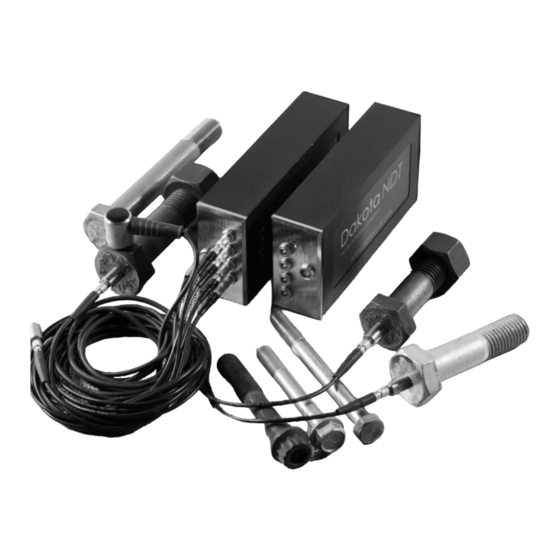
- Page 1 OPERATION MANUAL DAKOTA NDT MultiMax Ultrasonic Bolt Tension Monitor – 4 Channel MUX P/N Z-226-0001 Rev 1.00, July 2024...
-
Page 3: Table Of Contents
....................... 2 ENERAL ISCLAIMER 1.2 S ..........................2 AFETY 1.3 W ........................2 ARRANTY CHAPTER TWO MULTIMAX HARDWARE CONNECTIONS ......3 2.1 T & B ................3 OTTOM ONNECTORS CHAPTER THREE MULTIUI – INTERFACE SOFTWARE ....... 5 3.1 O ........................5 VERVIEW 3.2 M... - Page 4 CHAPTER NINE MEASURING SYSTEM ZERO (CALIBRATION) ....36 9.1 I ........................ 36 NTRODUCTION 9.2 C ..................36 ALIBRATION ISNOMER 9.3 C ......... 37 REATING A ROUP TO OCUMENT ALIBRATION DATA 9.4 A ....................38 ALIBRATION CHAPTER TEN TEMPERATURE COMPENSATION ........42 10.1 P ........................
- Page 5 16.2 D (.SM2) ......................75 16.3 D (.CSV) ......................76 16.4 S ) ..................77 TORING AMPLE 16.5 S ) ....................77 TORING ANUAL CHAPTER SEVENTEEN SOFTWARE, FILE TRANSFER, & UPGRADES ..79 17.1 C ................79 OMPUTER YSTEM EQUIREMENTS 17.2 I UI & D ..................79 NSTALLING ULTI...
-
Page 7: Chapter One Introduction
CHAPTER ONE INTRODUCTION The MultiMax is a 4 channel ultrasonic bolt monitor used to measure the stretch (elongation, load, stress and %strain) of a fastener under tension. This is accomplished ultrasonically by sending an ultrasonic wave down the length of the fastener and accurately measuring the change in transit time between an unloaded versus loaded fastener/bolt, and calculating a physical stretch. -
Page 8: General Disclaimer
Use of the MultiMax for any other purpose, or in any other manner than described in this manual invalidates the warranty and can result in serious electric shock, injury, and even death. -
Page 9: Chapter Two Multimax Hardware Connections
The USB-C connector, located on the bottom end cap, provides both power and data to the MultiMax when connected directly to a computer or USB hub. The cable supplied with the MultiMax is a USB type C to a USB type A (pt# N-003-0330). - Page 10 Dakota NDT Note: This connector is also used to upgrade the MultiMax with the latest version of firmware.
-
Page 11: Chapter Three Multiui - Interface Software
MultiUI is a software interface program written to work in conjunction with one or more MultiMax four channel modules (hardware). Since the MultiMax module is not equipped with a physical hardware display, the MultiUI software will take over as the visual component for each module and channel detected. - Page 12 Dakota NDT Note: During the installation process the user will be prompted to either accept the default installation directory, or select a custom directory location. If a custom folder is selected, all the executable, library, and text configuration files will automatically be stored in the custom folder location. However, if the default directory is accepted, the executable and library and files will be populated in ‘ProgramFiles/MultiUI’...
-
Page 13: Control Panel
The photo above is a snapshot of the main control panel summary page, with a single MultiMax module connected, and the four active channels identified. Bolt #1 & 2 are live and measuring, while #3 & 4 available for use. - Page 14 Reports the number of stored measurements recorded. Port_Ch – Shows the current COM port assigned to the specific MultiMax module, as well as all the independent channels for each module. The example above shows a single module assigned to COM14 with four independent channels. A number of modules can be connected together at the same time, and MultiUI will assign independent ports for each module.
-
Page 15: Menus & Features
MultiMax Bolt Tension Monitor 3.4 Menus & Features The menu options above (Edit, Preferences & About) contain the menu item features currently available in the MultiUI control panel and are referenced as follows: Edit Menu Add Gauges – Initiates a search for gauges connected on com port devices. When MultiUI is first launched, this routine will be run automatically. -
Page 16: Display Interface & Menus
If another serial device is connected to the computer that has nothing to do with MultiMax (i.e. serial converter cable, or Bluetooth device), the com port can be ‘excluded’ from MultiUI port scanning, by selecting the com port(s) in the list displayed. - Page 17 MultiMax Bolt Tension Monitor Navigation and operation of the MultiMax will be done using the MultiUI interface display as shown in the diagram above. Opening a specific channel will activate this display window with the settings and status for that specific channel. The following are brief explanations of the feature/items contained in the MultiUI display window: A.
-
Page 18: Tabbed & Hot Menu Reference
AUTO SET is an automatic measurement routine that attempts to locate the detection and set all the scope parameters of the MultiMax. Pressing the STORE key will save the current measurement to the group log file. - Page 19 MultiMax Bolt Tension Monitor The following table is a quick menu reference guide. The MultiUI display interface has 6 top level menu labels, and multiple sub menu (hot menu) items for each label. In the photo above, A represents the menu tab MEAS, and B displays the hot menu items contained in MEAS.
-
Page 20: Display Menu Reference
Provides descriptive information regarding the hardware module and interface firmware. Mount Drive – Loads the file system of the MultiMax internal SD card, making the files accessible to open and view the contents on a computer. Firmware upgrade files and all... - Page 21 The CAL_ZERO_DATA files are viewable in DakView PC software. Upgrade Firmware – Allows the MultiMax the ability to be upgraded in the field to the latest version of firmware. This is specific to the hardware MultiMax module, which is separate from the MultiUI interface software.
-
Page 22: Chapter Four Quick Start Guide
4.2 Getting the MultiMax ready Making all the connections In order to get the MultiMax ready for operation, the following connections must be made: 1) Connect a MultiMax module directly to the computer, or USB hub connected to a computer. -
Page 23: Configuring Multiui
4.3 Configuring MultiUI In this section the MultiMax will be setup in its simplest form. The 3” cal bar, typically used for the system zero calibration, will be used as the bolt in this quick start example. - Page 24 Dakota NDT the port is COM14, and the channel is B1 (bolt #1) by default. The location names can be edited as needed. Since only a single transducer connected to the first channel is coupled to the 3” cal bar, it is the only channel currently measuring and perfectly stable at max stability of 100.
- Page 25 MultiMax Bolt Tension Monitor 4) Click the MATL tab at A to display the MATERIAL menu items A. 5) Click the down arrow to display the material list, and select the TYPE at B. 6) Click the GEOM tab at A to display the GEOMETRY menu items A.
- Page 26 9) Click the down arrow to display the utilities list options and select the TEMP MODE at B. 10) The MultiMax is now configured and ready to measure. Click the MEAS tab at A to return to the main measure display screen A.
- Page 27 MultiMax Bolt Tension Monitor 11) Click the AUTO SET tab at B, to allow the MultiMax to automatically optimize settings and measure the unloaded reference length (L-Ref). 12) Once the AUTO SET has completed, the measurement can be stored. Click the STORE tab at A to record the unloaded length and display LIVE at Note: When the reference length measurement is stored, a number of parameters will be ‘locked’, and inaccessible.
- Page 28 Dakota NDT 13) Once the target elongation/stretch is reached at A, click the STORE tab at B to record the loaded length and complete the measurement procedure for the first bolt on channel #1. 14) Click on the MultiUI control panel window to review the recorded results A, and number of stored loaded lengths at B.
- Page 29 MultiMax Bolt Tension Monitor the control panel location column, in this example the default is ‘U- COM14_B1’. Additionally, a ‘history.csv’ file is also automatically created and updated with the group file data for the purpose of importing the file into a number of third party software programs.
-
Page 30: Chapter Five Remote Commander
This section is optional for those who wish to develop their own application software for use with the MultiMax. The MultiMax has a built-in command structure ‘Remote Commander”, which offers full control of the gauge from any command line terminal software program via a serial connection, and using a USB CDC class driver (Serial over USB). - Page 31 MultiMax Bolt Tension Monitor Configuring PuTTY Note: This section assumes the MultiMax is connected to a USB port on a PC, powered on, and PuTTY has been downloaded/installed on the PC connected. Refer to Chapter Two for hardware connections. 1) Locate the serial port MultiMax is currently connected to. This can be found...
- Page 32 Dakota NDT 2) Start the PuTTY software program for configuration. Select the connection type D, the Serial Line B, the Speed C, and a name to save the Session to eliminate having to repeat the configuration process again at E.
- Page 33 5) Select Session option in Category, and Save to store all settings in the session, and finally launching the terminal shell by selecting Open at J. Note: MultiUI cannot be running when attempting to connect to the MultiMax module with PuTTY or other terminal interface program. Close the MultiUI...
- Page 34 Dakota NDT 6) With the terminal shell running, type ‘help’ enter to display the command list in remote commander. 7) In the example above, the ‘rev’ command displayed the currently version of firmware 3.07C, and the ‘about’ command all the gauge and company...
- Page 35 MultiMax Bolt Tension Monitor Note: Contact Dakota NDT for additional documentation for remote commander.
-
Page 36: Chapter Six Theory Of Operation
The digital signal processor optimizes the measurement process. 6.2 Purpose The MultiMax measures the actual clamp load produced by tightening a fastener. It is capable of measuring in quantities of time(nanoseconds), elongation, load, stress, or %strain in variety of common materials from approximately 1 inch to 50 feet in... -
Page 37: Ultrasonic Waves
6.4 Measurement Mode The MultiMax uses a standard pulse-echo (P-E) mode for measurement. This is accomplished by measuring from the initial pulse (sometimes referred to as an artificial zero) to the first echo (reflection). In this mode errors can result from surface coatings applied to the bolt, as well as temperature variations. -
Page 38: Chapter Seven Bolt Preparation
7.1 Use of Ultrasonic Couplant Sonic energy at the frequency range used by the MultiMax travels well through solid materials and most liquids. It does not travel well through air. This variable resistance to the passage of sonic energy is called sonic impedance. The sudden change in... - Page 39 MultiMax Bolt Tension Monitor Smooth, even surfaced bolt ends that seat the entire active surface of the transducer with minimum gap are required for accurate signal transmission. Bolt ends may need to be cleaned, ground, etc., to achieve the required surface.
-
Page 40: Bolt End Reflectors
Dakota NDT 7.3 Bolt End Reflectors Smooth, flat reflecting bolt ends that are perpendicular to the axis of the bolt are required for accurate echo reception. Bolt ends may need to be cleaned, ground, etc., to achieve the required surface. -
Page 41: Chapter Eight Transducer Selection
8.1 Selecting the Transducer Transducer selection is an important part of getting the best results from the MultiMax. The frequency and diameter of the transducer should be carefully selected using the following information: Select the largest diameter transducer that will nicely seat on the end of the bolt. -
Page 42: Chapter Nine Measuring System Zero (Calibration)
These items should be documented for future reference. While the MultiMax can be used for a variety of applications, like the MiniMax and Max II gauges, it was developed with the intention of those applications seeking some form of ‘permanent monitoring’... -
Page 43: Creating A Group To Document Zero (Calibration) Data
MultiMax Bolt Tension Monitor instrument. Check in with your quality department to verify their duration requirement for “Test & Measurement Equipment”. 9.3 Creating a Group to Document Zero (Calibration) data A project folder named “CAL_ZERO_DATA” will automatically be created as a sub folder in the ‘GroupLogs’... -
Page 44: Auto - Zero/Calibration
The process is fully automated and easy to use. If valid signals cannot be acquired during the ‘auto set’ routine, the MultiMax will report an error. If this occurs, try relocating the transducer to various positions on the end of the 3”... - Page 45 MultiMax Bolt Tension Monitor calibration bar. This will avoid creating a couplant film layer between them, causing an “out of tolerance” condition > +/- 0.001” for the 3” cal bar. Auto System Zero Note: The auto option will perform a two-point calibration using a single 3” cal bar (pt# X-000-0011) and measurements of 1x &...
- Page 46 Dakota NDT 4) Click the RUN button in AUTO CAL to initiate the calibration process. The RUN button will now display WAIT at A, and a dialog box will appear at B as the automated process is underway. Once the dialog box is no longer displayed, the ZERO CALIBRATION has completed.
- Page 47 MultiMax Bolt Tension Monitor bar. If diameter of the transducer is relatively smaller than the diameter of the cal bar, consider moving the transducer location towards the edge of the cal bar to avoid sidewall noise, and repeat step 4. When the dialog box is no longer displayed, the zero calibration has been successfully completed and documented in the CAL_ZERO_DATA folder.
-
Page 48: Chapter Ten Temperature Compensation
The thermal expansion of the fastener and the ultrasonic change in velocity, as a result of temperature, are two separate effects. However, for the purpose of the MultiMax, they are combined in a single factor known as the Temperature Coefficient (Tc). The sections that follow outline the procedures for selecting and using the temperature compensation mode with the accessory temperature sensor. - Page 49 MultiMax Bolt Tension Monitor 1) Click the UTILS tab at A to display the UTILITIES menu items. 2) Click the down arrow to display the TEMP MODE options and select the temperature mode at B.
- Page 50 Dakota NDT Note: If the “manual” option is selected and an external temperature device will be used, or in a climate controlled environment, be sure to enter the correct temperature in the TEMP field prior to storing a measurements. 3) Click the MEAS tab at A to display the MEASURE menu items.
-
Page 51: Chapter Eleven Bolt Material Calibration
BOLT MATERIAL CALIBRATION 11.1 Why Calibrate? The preset bolt types in the MultiMax contain average factors for the material type. These are approximate values only. In a tightly controlled application where extreme accuracy is required, it is necessary to obtain all the information possible about the fasteners being measured. - Page 52 Dakota NDT 1) Click the GEOM tab at A to display the GEOMETRY menu items. 2) Click the down arrow to display the QUANTITY options and select ELONG at B. 3) Click the MATL tab at A to display the MATERIAL menu items.
- Page 53 MultiMax Bolt Tension Monitor 4) Click the down arrow to display the TYPE options and select the material type at B. Note: If the material type is not in the list of types, select a similar type. This step is only to get the velocity value in close proximity – not critical. Write down the velocity of the material type selected.
-
Page 54: Stress Factor Calibration
Dakota NDT 8) Click the AUTO SET tab at C to activate the Auto Set routine and display the Ultrasonic Length. PhysicalLe ngth CurrentVel ocity CorrectVel ocity Ultrasonic Length 9) Calculate the correct velocity using the equation displayed above. - Page 55 Sonic Stress Factor is to be determined. Notes: The Dakota NDT MultiMax must be calibrated, or zeroed, as described in the Zero Calibration procedure section Error! Reference source not found.. The Velocity Calibration should be performed prior to determining the Stress Factor.
- Page 56 Note: The following steps assume that the user has performed the steps in the previous section and calibrated the velocity. Therefore, the velocity has been adjusted, approximate length already entered, and the MultiMax is currently setup and ready to measure in elongation mode.
- Page 57 MultiMax Bolt Tension Monitor working conditions. Using the mechanical measuring device, measure and record the Mechanical Length at Load 1 “L ” for the current sample bolt. 6) Apply a drop of couplant to the bolt or transducer, and attach it to one end of the bolt.
-
Page 58: Temperature Factor Calibration
68 F. If the temperature of the fastener is currently being measured at 108 F, the MultiMax will compensate, or correct, the measurement back to 68 F. Note: This is an arbitrary temperature range only. The primary thing to consider is to use a respectable temperature range with at least 5 different temperature points. - Page 59 Temperature Factor is to be determined. Notes: The Dakota NDT MultiMax must be calibrated, or zeroed, as described in the procedure entitled Measuring System Zero in 9.1. The sample bolts should be left to soak at the measured temperature points for a period of not less than 20 minutes, to insure that temperature is uniform throughout the sample.
- Page 60 Dakota NDT transducer and bolt. Be sure to always place the transducer in the same location. This will help to eliminate any potential measurement errors caused by changing the sound path. 3) Record the ultrasonic length “L ” of the sample bolt at the above minimum temperature - 48 ) –...
-
Page 61: Chapter Twelve Load Measurment
The cross sectional area of the bolt is defined as the average area of a fastener under stress. This factor is only used in the MultiMax’s calculation of load. It has no effect on stress or elongation, time, or strain, and is directly proportional to the load measured ultrasonically. - Page 62 Dakota NDT For bolts with complex geometry, the areas should be estimated by averaging each individual area and length. In the case of a hollow fastener, the area of the hole must be subtracted from the overall area. The area of a fastener with complex geometry can be estimated as follows: ...
-
Page 63: Calibrating Load Factor (Field Calibration)
A field calibration is accomplished using a tensile tester, load cell, or other calibrated load device to compare known loads against ultrasonic elongations. The MultiMax is equipped with a self- calibrating feature that uses a linear regression or vector equation to produce a best-fit line through the known loads, minimizing error. - Page 64 Elongation (in time as measured by MiniMax) Note: This calibration feature/option is not offered as part of the MultiMax platform, as it was designed to be focused as a multi channel platform for permanent monitoring. If bolt material calibrations are required, a separate Max II or MiniMax,...
-
Page 65: Chapter Thirteen Measurement Formulas
MEASUREMENT FORMULAS 13.1 Measurement Quantities The MultiMax has the ability to measure in a number of measurement quantities: Time (nanoseconds), Elongation, Load, Stress, and Strain (in terms of %). While there are a number of quantity options available, the easiest and most fail safe quantities to consider are Time and Elongation. -
Page 66: Chapter Fourteen Waveform Display
WAVEFORM DISPLAY 14.1 RF Waveform Display The MultiMax offers a single radio frequency (RF) waveform display with digital readout. The waveform is a graphical representation of the sound reflections traveling through a fastener and echoing back to the transducer/gauge. The sound energy echoed back from the end of the bolt (amplitude) is displayed on the vertical axis, and time is displayed in terms of length on the horizontal axis. -
Page 67: Display Area (Delay & Width)
MultiMax Bolt Tension Monitor 14.2 Display Area (Delay & Width) The DELAY & WIDTH features are similar to a zoom function. While the DELAY setting specifies where the left side of the A-Scan display area starts on the horizontal X axis, in terms of distance/depth, the WIDTH setting specifies the viewable distance/range starting from the DELAY on the same X axis. -
Page 68: Gate
Dakota NDT RF wave symmetrical, inside of the boundaries of ‘full screen height (FSH)’, and not ‘clipping’ or overloading the input. Additionally, if the reflective ends of a fastener are no longer parallel due to deformation or bending, the amplitude lost can often be recovered by manually increasing the gain to maintain the original signal amplitude. - Page 69 MultiMax Bolt Tension Monitor The MultiMax is equipped with a single gate with a start and threshold level. Detection can occur only within the boundaries of the gate, and is sometimes referred to as a ‘blocking gate’. To avoid detection on a signal occurring prior to the desired signal, in terms of length/depth, the start of the gate can be adjusted to occur after the unwanted signal forcing the MultiMax to look ahead to the next available echo.
-
Page 70: Threshold
Dakota NDT 1) Click the MEAS tab at A to display the MEASURE menu items. 2) Use the auto scroll arrows to increase/decrease the GATE start setting at B. Alternatively, click inside the numeric field at B to edit manually using the keyboard. -
Page 71: Interpreting The Waveform (Polarity)
THRESHOLD level. 14.6 Interpreting the Waveform (Polarity) One of the most important things to consider, when using the MultiMax, is how to interpret the waveform in order to choose the proper phase POLARITY and gain settings. It’s also important to understand what’s taking place during measurement. - Page 72 When this occurs, the decrease in amplitude can cause the MultiMax to lose the first half cycle altogether. If the first cycle is lost, the MultiMax will “peak Jump” to another cycle later in time with greater amplitude.
- Page 73 The Auto Set feature built into the MultiMax will attempt to optimize these settings for you.
-
Page 74: Automatic Echo Optimization (Auto Set)
14.7 Automatic Echo Optimization (Auto Set) The MultiMax is equipped with a built in Auto Set feature for echo optimization. The AUTO SET uses a variety of algorithms, evaluating the positive and negative cycles to select the best polarity to use for measurement. It also optimizes the gain, sets the delay and width, and activates and sets the gate and threshold levels. - Page 75 MultiMax Bolt Tension Monitor 4) Click the AUTO SET tab at C, to allow the MultiMax to automatically optimize reference length (L-Ref) settings. Note: In order for the AUTO SET to function as intended, the approximate length of the fastener must be set. The approximate length tells the MultiMax where to start looking for the echo, by searching +/- 5% from the value entered.
-
Page 76: Chapter Fifteen Additional Features
ADDITIONAL FEATURES 15.1 Quality/Correlation (Transducer Placement) The auto correlation feature in the MultiMax is designed to assist the user with returning the transducer back to the original position and orientation where it was during the initial reference length measurement. Since the sound path is changing,... -
Page 77: Pulse Width
MultiMax Bolt Tension Monitor 15.2 Pulse Width The MultiMax has a 200 volt square wave pulser. Pulse width, refers to the duration of time the pulser is left on. This time results in increased/decreased energy sent into the fastener. There are three pulse width options (SPIKE, THIN, and WIDE), with adjustable pulser voltages of 100, 150 and 200 volts. -
Page 78: Digitizer
Dakota NDT settings are best for longer bolts with attenuative or inconsistent materials. The procedure to change the PULSER VOLTAGE is outlined below: Selecting Pulser Voltage 1) Click the TUNE tab at A to display the TUNE SIGNAL menu items. -
Page 79: Default Setup
MultiMax Bolt Tension Monitor Setting the Digitizer 1) Click the TUNE tab at A to display the TUNE SIGNAL menu items. 2) Click the down arrow to display and select the DIGITIZER setting at B. 3) Repeat step 2 above for the desired setting. - Page 80 Dakota NDT 1) Click the UTILS tab at A to display the UTILITIES menu items. 2) Click the LOAD button to load the DEFAULT SETUP at B. 3) Repeat step 2 above for the desired setting.
-
Page 81: Chapter Sixteen Data Storage - Setup, Edit, & View Files
When a four channel MultiMax is connected to a PC, and MultiUI running, all four channels will be recognized and assigned to a serial COM port. Once configured, measurements made and stored, individual ‘.SM2’... -
Page 82: Data File (.Csv)
Dakota NDT 16.3 Data File (.CSV) The ‘.CSV’ file is a preformatted comma separated file that can be used to import into a number of report editors and spreadsheet programs for documentation or trending. -
Page 83: Storing Data (Sample Rate)
MultiMax Bolt Tension Monitor 16.4 Storing Data (Sample Rate) To automatically store data, set the sample rate to occur at a preferred time interval. Store Data - Auto 1) Click the PREFERENCES menu and select SAMPLE RATE to enable and set the time interval. - Page 84 Dakota NDT 1) Click the STORE tab at A to store an individual measurement for the bolt/channel selected.
-
Page 85: Chapter Seventeen Software, File Transfer, & Upgrades
DakView and used as a file viewer for reporting purposes. 17.4 Line Power The MultiMax is powered through the USB-C connector to either a USB or Ethernet hub. If only a single four channel module is used, it can be plugged directly into a USB port on a computer, or into a common mobile phone power adaptor. - Page 86 Dakota NDT Upgrading the Firmware 1) Double click on the “MultiUI” shortcut to activate the control panel. 2) Double click on one of the channel location labels A to display the MultiUI interface display window. 3) Click HELP and select Mount Drive to activate the SD storage device.
- Page 87 MultiMax Bolt Tension Monitor 4) Click the OK button to mount the drive, or CANCEL to abort. Note: Once the external drive has been mounted, the directory folder will appear with all the files and directory folders currently being stored on the SD card.
- Page 88 Dakota NDT 6) Click HELP and select the Upgrade Firmware option to begin the upgrade process. 7) Click the OK confirmation button to start the upgrade, or CANCEL to abort. Note: A progress and bar and warning message will be displayed during the...
- Page 89 MultiMax Bolt Tension Monitor 8) Click HELP and select the ABOUT option to display the current version of firmware installed B.
- Page 90 Dakota NDT warrants transducers and accessories against such defects for a period of 90 days from receipt by the end user. If Dakota NDT receives notice of such defects during the warranty period, Dakota NDT will either, at its option, repair or replace products that prove to be defective.
Need help?
Do you have a question about the MultiMax and is the answer not in the manual?
Questions and answers