
Related Manuals for Dakota NDT PMX4-DL


Summary of Contents for Dakota NDT PMX4-DL
- Page 1 OPERATION MANUAL Dakota NDT High Penetration A/B Scan Thickness Gauge P/N P-225-0004 Rev 1.00, January 2024...
-
Page 2: Table Of Contents
CONTENTS CHAPTER ONE INTRODUCTION ..............1 1.1 D ......................... 1 ISCLAIMER CHAPTER TWO QUICK STARTUP GUIDE ............2 2.1 PMX4-DL O ......................2 VERVIEW 2.2 T & H ..................5 ABBED EFERENCE 2.3 S ..................7 ELECTING THE RANSDUCER 2.4 P &... - Page 3 CHAPTER EIGHT THRU PAINT MEASUREMENT TECHNIQUE....69 8.1 I ..............69 NTRODUCTION TO AINT EASUREMENT 8.2 U ....................69 SING AINT CHAPTER NINE ADDITIONAL FEATURES OF THE PMX4-DL ..... 72 9.1 U ..........................72 NITS 9.2 B ........................73 ACKLIGHT 9.3 C ......................... 73 ONTRAST 9.4 R...
- Page 4 12.1 C ................128 OMPUTER YSTEM EQUIREMENTS 12.2 I ..................... 128 NSTALLING 12.3 C PMX4-DL ................128 OMMUNICATING WITH THE 12.4 L ........................128 OWER 12.5 U PMX4-DL .................... 128 PGRADING THE APPENDIX A - VELOCITY TABLE ..............130 APPENDIX B - SETUP LIBRARY ..............132 ...
-
Page 5: Chapter One Introduction
1.1 Disclaimer The PMX4-DL is a full-featured scope that allows a great deal of control over the functionality and electronic performance of the instrument. However, as this provides the user greater control and versatility for a variety of applications, it also requires that the user be comfortable with operation and waveform interpretation of the instrument. -
Page 6: Chapter Two Quick Startup Guide
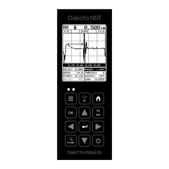
CHAPTER TWO QUICK STARTUP GUIDE Turn the PMX4-DL on and off using the switch located on the bottom right corner of the keypad. When PMX4-DL is initially turned on, a flash logo and blinking lights will be displayed prior to entering into the main measurement screen. Note: This section is primarily written as a basic startup guide only. - Page 7 (250 Hz), depending on which measurement mode and features are enabled. B. Battery Icon – Indicates the amount of battery life the PMX4-DL has remaining. C. Velocity – The material velocity value the PMX4-DL is currently using or calibrated for.
- Page 8 Dakota NDT M. Hot Menu items – We call this menu section our “hot menu”, as these items are the most commonly adjusted features, requiring quick access from the user. They can be displayed and scrolled by pressing the key at anytime.
-
Page 9: Tabbed & Hot Menu Reference
The PMX4-DL has 11 tabbed menu titles and multiple submenu items as illustrated below. The PMX4-DL also has 1 ‘hot menu’... - Page 10 Dakota NDT >> End DATA UTILS XFER AUTO FIND UPGRADE GAUGE EDIT SCAN MODE CAPTURE VIEWER OPEN ALARM ABOUT CLOSE ALARM HIGH DELETE ALARM LOW ONE FILE DELETE DIFFERENTIAL ALL DATA KEY CLICK SET DATE SHOW DATE...
-
Page 11: Selecting The Transducer Type
2.3 Selecting the Transducer Type The first step for using the PMX4-DL is to select the transducer type. There are 2 different types; contact and delay line. The contact options consist of 1/8” to 1” diameters and 1-10 MHz frequencies, as well as a custom 500 kHz delay line transducer as the primary transducer option. -
Page 12: Probe Zero & Calibration
2.4 Probe Zero & Calibration The next steps are to perform a probe zero and calibrate the PMX4-DL to a specific material type. If the sound velocity is unknown, the PMX4-DL can be calibrated to a known thickness sample. -
Page 13: One Point Material Calibration
6) Proceed to the calibration section. Note: The value that is displayed will change depending on the current velocity setting in the PMX4-DL. Disregard the number that is displayed. It is not important. What is important is accurately performing the steps outlined above to insure reliability of the probe zero calculation. - Page 14 Dakota NDT 1) Physically measure an exact sample of the material or a location directly on the material to be measured using a set of calipers or a digital micrometer, and if a calibration standard will not be used. 2) Apply a drop of couplant on the transducer and place the transducer in steady contact with the cal standard or test material.
-
Page 15: Measure
If the thickness is not correct, repeat the steps above. 2.5 Measure The PMX4-DL is now ready to measure. There are four different measurement view options, each with a specific purpose – Digits, RF, RECT, & B-Scan. The steps... - Page 16 Digits View DIGITS: Displays the digital thickness value using a large font size. This view is useful when the PMX4-DL is intended for use as a basic thickness gauge. RF: Displays the actual waveform signal, much like an oscilloscope, from the reflection of the opposite surface.
- Page 17 PMX4-DL High Penetration Thickness Gauge RECT: Displays a half waveform signal, either positive or negative, from the reflection of the opposite surface. The user can select the polarity or “phase” displayed. This is typically determined by first using RF view to select the most optimal polarity “phase”, setting the polarity, and switching to RECT view.
- Page 18 Dakota NDT 4) Press the key once to activate measure menu items. Press the key multiple times to move right and the key multiple times to move left, until the either the DELAY (START) or RANGE (DEPTH) cell is highlighted.
-
Page 19: Chapter Three Keyboard, Menu, & Connector Reference
CHAPTER THREE KEYBOARD, MENU, & CONNECTOR REFERENCE 3.1 Menu Key (Operation & Sub Menus) The Menu key activates the primary menu structure containing 8 menu tab groups. These tab groups then contain sub menu items, or functions. The sub menu items have been organized in tab groups according to how closely they are related to the individual tab group names. -
Page 20: Probe - Menu
Dakota NDT Activating and Getting Around in the Menu Items 1) Press the key once to activate the menu items tab. Press the multiple times to tab right, and the key multiple times to tab left until the desired tab group is highlighted and displaying the submenu items. The tab groups are illustrated above (A). -
Page 21: Cal - Menu
PMX4-DL High Penetration Thickness Gauge ZERO PROBE: The PMX4-DL is zeroed in much the same way that a mechanical micrometer is zeroed. If the PMX4-DL is not zeroed correctly, all of the measurements made using the PMX4-DL may be in error by some fixed value. The manual (on block) option is available for single contact transducer types in pulse echo (P-E) measurement mode, and the ‘auto zero’... -
Page 22: Tune - Menu
Refer to page 76 for further info. PULSE: The PMX4-DL has adjustable pulse width options for both the 200 & 400 volt pulsers. The adjustable 400 volt tone burst pulser has tuned burst options at... -
Page 23: Gt1 - Menu
Refer to page 80 for further info. GAIN: The PMX4-DL has 110dB gain range from (-35 to 75 dB). This feature is used to increase/decrease the power or amplitude of the signal. Similar to turning the volume up or down on a stereo receiver. -
Page 24: Gt2 - Menu
Dakota NDT GATE1 WIDTH: This feature allows the user to set the overall width of the gate, in terms of distance, from the starting value of Gate1. Refer to page 62 for further info. THRESHOLD1: Enables the user to set the sensitivity level of Gate1. The amplitude of the signal must reach or exceed the threshold level to detect and measure. -
Page 25: Data - Menu
Refer to page 123 for further info. DEFAULT SETUP: Loads a basic default setup. Use only as a last resort when the setups in the PMX4-DL have been corrupted and a computer is not accessible. Refer to page 125 for further info. -
Page 26: Util (Utilities) - Menu
PMX4-DL. Refer to page 91 for further info. SHOW DATE: Gives the user the ability to display the date and time in the waveform area of the PMX4-DL. The options are OFF, DATE, TIME, BOTH. Refer to page 93 for further info. -
Page 27: Clr (Clear) Key
PMX4-DL High Penetration Thickness Gauge ABOUT: Provides the user with Dakota NDT contact information and the PMX4-DL firmware version. Refer to the Dakota NDT web site for information on the latest firmware versions available for download. 3.13 CLR (clear) Key The primary function of the CLR key is to clear a measurement, or set an obstruct (obstruction) in a grid or sequential log. -
Page 28: Enter Key
Dakota NDT The Arrow Keys are used to navigate through the menus, increase/decrease values, and toggle specific function keys. 3.18 ENTER key The ENTER key is used in the overall menu selection process to activate list and edit boxes, and display and save measurements to grid or sequential file. -
Page 29: Top & Bottom End Caps
The USB-C connector, located on the bottom end cap, is a mini type C female connector. It is designed to connect directly from the PMX4-DL to a standard USB type A port on a PC. The cable supplied with the PMX4-DL is a USB type C to a USB type A (pt# N-003-0330). -
Page 30: Chapter Four Principals Of Ultrasonic Measurement
CHAPTER FOUR PRINCIPALS OF ULTRASONIC MEASUREMENT 4.1 Time versus thickness relationship Ultrasonic thickness measurements depend on measuring the length of time it takes for sound to travel through the material being tested. The ratio of the thickness versus the time is known as the sound velocity. In order to make accurate measurements, a sound velocity must be determined and entered into the instrument. -
Page 31: Measurement Modes
4.6 Measurement Modes In this section we will discuss the different measurements modes the PMX4-DL is capable of operating in, the transducers required, and the reasons for using specific modes:... - Page 32 (reflection). The transducer is placed on a reference disk, located on the top of the PMX4-DL, and the zero function is executed to establish a zero point for the transducer. Surface coatings and temperature variations will produce errors in this mode.
- Page 33 PMX4-DL High Penetration Thickness Gauge Echo-Echo-Verify Waveform Echo-echo verify mode measures between three reflections. Similar to E-E mode, this technique is commonly used to eliminate errors from surface coatings and also as verification of echo-echo mode, as it compares the 1 &...
-
Page 34: Chapter Five Making Measurements
The sound velocity can be selected from a material chart in the manual, selected from a material list in the PMX4-DL, or for greater precision determined from a mechanically measured sample of the test material. - Page 35 PMX4-DL High Penetration Thickness Gauge 1) Press the key once to activate the menu items tab. Press the multiple times to tab right and the key multiple times to tab left until the PRB menu is highlighted and displaying the submenu items.
-
Page 36: Probe Zero
5.2 Probe zero All the transducer types in the PMX4-DL will require either a ‘manual (On Block)’ zero (contact style probes), or an ‘auto (Off Block)’ zero (500 kHz delay line probe) if pulse-echo measure mode will be used. If a contact transducer type was selected and will only be used in the echo-echo measure mode, proceed to the next section. - Page 37 PMX4-DL High Penetration Thickness Gauge Note: Couplant must be removed from the face of the probe and the transducer ‘not’ in contact with any material. 1) Press the key to activate the menu items tab. Press the multiple times to tab right and the key multiple times to tab left until the PRB menu is highlighted and displaying the submenu items.
- Page 38 Dakota NDT Manual Zero (On Block) 1) Apply a drop of couplant on the transducer and place the transducer in steady contact with the probe zero disk. Obtain a steady reading. 2) Press the key to activate the menu items tab. Press the...
-
Page 39: Material Calibration
5.3 Material Calibration In order for the PMX4-DL to make accurate measurements it must be set to the correct sound velocity of the material being measured. Different types of materials have different sound velocities. For example, the velocity of sound through steel is about 0.233 inches per microsecond, versus that of aluminum which is about 0.248... - Page 40 As previously stated, the PMX4-DL has a one or two point calibration option. The one point calibration option is most suited for linearity over large ranges. It’s best to...
- Page 41 The procedure to perform a ‘one point’ calibration is outlined below as follows: Note: It’s always handy to carry a set of mechanical calipers to use in conjunction with the PMX4-DL for calibration in the field. One Point Calibration Note: If a contact style transducer was selected, be sure a probe zero has been performed prior to performing the calibration procedure.
- Page 42 For example, if the measurement range was .080” (2.03mm) to .250” (6.35mm), it’s optimal to select two points close to the minimum and maximum thicknesses range. When a two point calibration is performed, the PMX4-DL calculates the zero and the velocity. The following steps outline this procedure:...
- Page 43 PMX4-DL High Penetration Thickness Gauge 1) Physically measure an exact sample of the material or a location directly on the material to be measured using a set of calipers or a digital micrometer. 2) Apply a drop of couplant on the transducer and place the transducer in steady contact with the sample or actual test material.
- Page 44 Dakota NDT 6) Press the arrow keys to scroll the digit locations. 7) Repeat steps 5 & 6 until the known thickness value is correctly displayed. 8) Press the key to calculate the zero/velocity and return to the menu screen, or to cancel the one point calibration.
- Page 45 PMX4-DL High Penetration Thickness Gauge 1) Press the key once to activate the menu items tab. Press the multiple times to tab right and the key multiple times to tab left until the CAL menu is highlighted and displaying the submenu items.
- Page 46 Dakota NDT 7) Finally, press the key to return to the measurement screen and begin taking readings.
-
Page 47: Chapter Six Display View Options
CHAPTER SIX DISPLAY VIEW OPTIONS The PMX4-DL has four different display options; Digits, RF, RECT and B-Scan. All views provide a digital thickness readout, and alarm limit tolerances if active. A key feature of the PMX4-DL is the A-Scan waveform display. The waveform is a graphical representation of the sound reflections, similar to an oscilloscope. - Page 48 When all the vertical bars are fully illuminated and the last digit on the digital thickness value is stable, the PMX4-DL is reliably measuring the same value multiple times per second. B. Battery Icon – Indicates the remaining amount of battery life.
- Page 49 When all the vertical bars are fully illuminated and the last digit on the digital thickness value is stable, the PMX4-DL is reliably measuring the same value multiple times per second. B. Battery Icon – Indicates the remaining amount of battery life.
- Page 50 Dakota NDT Gain Setting (Manual & Automatic (AGC)) E. Digital Material Thickness Value – Smaller font size with hot menu visible, and larger font in full screen mode. F. Scan Bar – Another view of material thickness in a deflection style horizontal bar.
- Page 51 When all the vertical bars are fully illuminated and the last digit on the digital thickness value is stable, the PMX4-DL is reliably measuring the same value multiple times per second. B. Battery Icon – Indicates the remaining amount of battery life.
- Page 52 Dakota NDT known as the threshold, and controls the sensitivity of the reflections that trigger a detection from the opposite surface of the material. F. Measurement Scale – Represents thickness values over a defined measurement range, and is labeled at the calibrated hash marks on the display (X) axis.
- Page 53 When all the vertical bars are fully illuminated and the last digit on the digital thickness value is stable, the PMX4-DL is reliably measuring the same value multiple times per second. B. Battery Icon – Indicates the remaining amount of battery life.
- Page 54 Dakota NDT F. Measurement Scale – Represents thickness values over a defined measurement range, and is labeled at the calibrated hash marks on the display (X) axis. G. Digital Material Thickness Value – The thickness of the base material. H. Minimum Thickness Value – Dynamically updates the minimum value during a scan, and displays the minimum thickness value found.
-
Page 55: Changing Display Options
PMX4-DL High Penetration Thickness Gauge 6.2 Changing Display Options The following procedure outlines how to select or toggle the display views: Changing Display View 1) Press the key once to activate the menu items tab. Press the multiple times to tab right, and the key multiple times to tab left, until the DISP menu is highlighted and displaying the submenu items. -
Page 56: Chapter Seven Adjusting The Scope
ADJUSTING THE SCOPE This chapter will focus on making adjustments to the A/B scan scope, using all the features available in the PMX4-DL. 7.1 Delay & Range (B-Start/B-Depth) The viewable range is set by adjusting the delay and range, with the delay controlling the start position of the left side of the display, and the range controlling the viewable area from the delay setting. - Page 57 PMX4-DL High Penetration Thickness Gauge 1) Press the key once to activate hot menu items. Press the multiple times to move right and the key multiple times to move left, until the DELAY cell is highlighted. 2) Press the arrow keys to scroll the highlighted value.
- Page 58 Dakota NDT Adjusting the Range (B-Depth) using the Hot Menus 1) Press the key once to activate measure menu items. Press the key multiple times to move right and the key multiple times to move left, until the RANGE cell is highlighted.
- Page 59 Adjusting the B-Scan Speed The PMX4-DL has the capability to adjust the scrolling speed of the time based B- Scan displayed in the gauge. The procedures to adjust the speed, only applicable if B-Scan view was selected, are outlined below:...
-
Page 60: Gain - Manual & Auto (Agc)
7.2 Gain – Manual & Auto (AGC) The gain, or amplification of the return echoes, can be adjusted in the PMX4-DL to accommodate a variety of applications. Gain is crucial in order to obtain valid readings during the measurement process. Too much gain may result in erroneous measurements, detecting on noise rather than the actual test materials back wall reflection. - Page 61 PMX4-DL High Penetration Thickness Gauge 1) Press the key once to activate measure menu items. Press the key multiple times to move right, and the key multiple times to move left until the GAIN/AGC cell is highlighted. 2) Press the arrow keys to scroll the highlighted value.
- Page 62 Dakota NDT The gain can also be adjusted from the tabbed menus. However, this method is more tedious than making the adjustments using the Hot Menu. The procedure using the tabbed menus is outlined below: Adjusting the Gain using the Tabbed Menus 1) Press the key once to activate the menu items tab.
-
Page 63: Threshold
The PMX4-DL is equipped with three independent gates, each with an adjustable threshold level. All three gates can be enabled only if a contact style transducer has been selected, and the mode is set to echo-echo-verify. - Page 64 Dakota NDT 1) Press the key once to activate measure menu items. Press the key multiple times to move right and the key multiple times to move left, until the THRESH(1-3) cell is highlighted. 2) If the correct THRESHOLD is displayed, press the arrow keys to scroll the highlighted value.
- Page 65 PMX4-DL High Penetration Thickness Gauge 7) Repeat steps 3-6 until all the THRESH values are correctly adjusted. The threshold can also be adjusted from the tabbed menus. However, this method is more tedious than making the adjustments using the Hot Menus. The procedure for...
-
Page 66: Understanding The Features Of The Gate
Dakota NDT 4) Alternatively, press the key to display the Digits Edit Box. 5) Press the arrow keys to scroll the highlighted value. 6) Press the arrow keys to scroll the digit locations. 7) Repeat steps 5 & 6 until the Threshold number is correctly displayed. - Page 67 PMX4-DL High Penetration Thickness Gauge Modes # Gates Gate # Start HoldOff Width Threshold 1,2,or 3 √ √ √ √ √ √ √ √ √ √ E-EV √ √ √ √ √ √ √ √ √ Diag. 1 Gate Features vs Modes Diag.
- Page 68 Dakota NDT Hold-Off: The hold-off is the starting point of the left side of gates 2 & 3, and is used only if a detection is found inside the previous gate. It should be considered as a delay from the detection point of the previous gate. When the hold-off is off, or 0, the gate will start at the point of detection from the previous gate.
-
Page 69: Gates
Refer to the Noise diagram: (A) refers to the noise in front of the actual back wall signal (C). Notice the start position of the gate. As a result, the PMX4-DL is detecting on the noise (A) as shown at point (B). However, the true measurement should be taken at point (C). - Page 70 The start of GATE1 has been moved just beyond the noise (A) to block the noise and detect on the correct signal (C). Note: The PMX4-DL will only detect on signals that are located inside the dimensions of GATE1 (B). Therefore, the PMX4-DL is blocked from detection at point (A), with the new starting point of the gate (B).
- Page 71 PMX4-DL High Penetration Thickness Gauge 3) Alternatively, if the correct ALL is not being displayed, press the to display the List Box. 4) Use the arrow keys to scroll through the List Box items until the correct ALL is highlighted.
- Page 72 Dakota NDT 1) Press the key once to activate the menu items tab. Press the multiple times to tab right, and the key multiple times to tab left, until the ALL menu is highlighted and displaying the submenu items. 2) Use the arrow keys to scroll through the sub menu items until ALL is highlighted.
-
Page 73: Chapter Eight Thru Paint Measurement Technique
With all of the measurement mode and multiple transducer options in the PMX4-DL, the primary through paint mode options are echo-echo (E-E) and echo-echo-verify (E-EV) using a contact style transducer. - Page 74 Note: Once the values of the fields have been changed or modified, these changes must be saved to a setup location prior to powering the PMX4-DL off. Failure to do so will result in losing your changes. Refer to page 119 for additional information on setups.
- Page 75 PMX4-DL High Penetration Thickness Gauge Notice that the amplitude of the cycle just to the left of (C). The amplitude of the cycle, at (C), is less than the amplitude of the cycle at (B), in terms of overall height.
-
Page 76: Chapter Nine Additional Features Of The Pmx4-Dl
ADDITIONAL FEATURES OF THE PMX4-DL 9.1 Units The PMX4-DL measures in both English and Metric units. Both have a high and low resolution option; IN, IN HR, MM, MM HR. Standard resolution is 0.01in (0.1mm), and HR resolution is 0.001” (0.01mm), or standard resolution at 0.01” (0.1mm). -
Page 77: Backlight
PMX4-DL High Penetration Thickness Gauge 9.2 Backlight The PMX4-DL LCD display is equipped with a backlight to adjust for various light conditions. There’s an ‘auto’ option that will only illuminate the display when coupled. Additionally, there’s a screen ‘invert’ for extreme sunlight conditions. -
Page 78: Rectified Wave Options
Dakota NDT Setting Contrast 1) Press the key once to activate the menu items tab. Press the multiple times to tab right and the key multiple times to tab left until the DISP menu is highlighted and displaying the submenu items. -
Page 79: Detect Mark
9.5 Detect Mark Another graphics option available in the PMX4-DL is the detection mark. There are a three options; dots, line, none. When enabled, displays a vertical line or dots where the detection point occurs on the wave. -
Page 80: Polarity
9.6 Polarity The PMX4-DL is equipped with an option to select the polarity, or phase +/-, for the purpose of detection. The phase can be a valuable feature when the signal returning from the test material is marginal because of a weak first positive or negative cycle. - Page 81 In this example the PMX4-DL is using a zero crossing method for detection. Therefore, the detect line (A) is represented by the broken vertical dotted line, and is currently detecting on the negative portion of the waveform (B) at the zero crossing (C).
-
Page 82: Pulse Width
9.7 Pulse Width The PMX4-DL has an adjustable pulse width option. Pulse width, refers to the duration of time the pulser is left on. This time results in increased energy sent into the test material. There are three width options for the 200 volt pulser (SPIKE, THIN, and WIDE), three width options for the high voltage 400 volt pulser (HV SPK, HV THIN, and HV WIDE). -
Page 83: Pulser Voltage
9.8 Pulser Voltage The PMX4-DL has an adjustable 200 volt spike pulser (100, 150, 200 volts), an adjustable high voltage 400 volt square wave pulser (200, 300, 400 volts), and an 400 volt tone burst pulser with tuned bursts at frequencies of (500 kHz, 1 MHz, 2 MHz, 5 MHz &... -
Page 84: Damping
9.9 Damping The PMX4-DL has a built-in damping feature to control the impedance input of the receiver. This enables the user the ability to match and optimize the transducer for better signal quality at various frequencies. The available settings are 50, 75, 100, 300, 600 and 1500 ohms. -
Page 85: Agc Max
PMX4-DL High Penetration Thickness Gauge 1) Press the key once to activate the menu items tab. Press the multiple times to tab right, and the key multiple times to tab left, until the TUNE menu is highlighted and displaying the submenu items. -
Page 86: Gain Slope (Tdg)
Dakota NDT 5) Press the key once to activate the menu items tab. Press the multiple times to tab right, and the key multiple times to tab left, until the TUNE menu is highlighted and displaying the submenu items. 6) Use the arrow keys to scroll through the sub menu items until AGC MAX is highlighted. - Page 87 PMX4-DL High Penetration Thickness Gauge The PMX4-DL has a gain slope feature that is similar to a basic linear time corrected gain function, or “time dependent gain” TDG. The slope can be adjusted from 0-40 decibels per inch depth. It can be used in all measurement modes (P-E, E-E, E-EV), and automatically tracks and starts just following first echo in multiple echo modes (E-E, E-EV).
-
Page 88: Tdg Start
Dakota NDT 2) Use the arrow keys to scroll through the sub menu items until GAIN SLOPE is highlighted. 3) Use the arrow keys to scroll the GAIN SLOPE value until the correct value is displayed to the right of the GAIN SLOPE menu item. -
Page 89: Auto Find
Suppose the PMX4-DL is currently setup with a delay of 0.000” and a range of 0.500”, but the target thickness measured is at 1.000”. Using the auto find will automatically adjust and setup the delay and range, bringing the waveform into view on the display. -
Page 90: High Speed Scan
9.14 High Speed Scan The High Speed Scan feature of the PMX4-DL increases the overall repetition/sample rate to 140Hz with a screen refresh rate of 25 times a second (25Hz). This feature enables a user to make scanned passes over an arbitrary length of the test material, while still maintaining a reasonable representation of thickness over the scanned area or region. -
Page 91: Alarm Mode
9.15 Alarm Mode The Alarm Mode feature of the PMX4-DL provides a method of setting tolerances, or limits, for a given application. This feature may be used for a variety of applications to verify the material is in allowable tolerance. There is a high & low limit option that can used together or individually. - Page 92 Dakota NDT 4) Continue on to the next section “Setting the Alarm Limits”. Setting the Alarm Limits 1) Assuming the ALARM is ON, use the arrow keys to scroll through the sub menu items until ALARM is highlighted. 2) Press the arrow keys to scroll the value.
-
Page 93: Differential Mode
9.16 Differential Mode The Differential Mode of the PMX4-DL provides the user with the ability to set a nominal value, according to what the expected thickness should be, and measure the +/- difference from the nominal value entered. This feature is typically used for quality inspections of incoming parts, or inspection during the manufacturing process. -
Page 94: Key Click
9.17 Key Click When a key is pressed on the PMX4-DL keypad, the user can control whether or not an audible beep is sounded and at what volume level, if any. The procedure for this feature/preference is outlined below:... -
Page 95: Set Date & Time
9.18 Set Date & Time The PMX4-DL is equipped with an internal clock to time and date stamp the log, setup and screen capture files for reporting/documentation purposes. The procedures for setting the time and date are outlined below:... - Page 96 Dakota NDT 1) Press the key once to activate the menu items tab. Press the multiple times to tab right and the key multiple times to tab left until the UTIL menu is highlighted and displaying the submenu items. 2) Use the arrow keys to scroll through the sub menu items until SET DATE is highlighted.
-
Page 97: Show Date & Time
The capture feature enables a user to capture the last viewed screen, give it a unique name, and save it to the internal SD card in the PMX4-DL. The screenshot will be saved as a tagged interface file (.tif), and can be viewed directly on the gauge, or using any PC graphics software viewer. -
Page 98: Capture Viewer
The capture viewer enables a user to view any of the saved screen captures on the SD card, using the PMX4-DL. This is handy if a PC isn’t available, but the user has a need to review the screen shots captured. - Page 99 PMX4-DL High Penetration Thickness Gauge The procedure to capture the last screen displayed is outlined below: Using the Viewer 1) Press the key once to activate the menu items tab. Press the multiple times to tab right and the key multiple times to tab left until the XFER menu is highlighted and displaying the submenu items.
-
Page 100: Chapter Ten Data Storage - Setup, Edit, & View Files
Multiple grids can be created and stored until the PMX4-DL’s memory is full. If the user attempts to store a new file in the PMX4-DL and the size of the file exceeds the capacity of memory, the PMX4-DL will respond with an error message indicating that the memory is unable to store the new file. -
Page 101: Creating A New Grid Or Sequential Log (File)
Dakota NDT Grid File Formats Sequential Log Formats Note: For the duration of this chapter, all references to GRIDS and SEQ LOGS should be considered synonymous with references to FILES. 10.2 Creating a new Grid or Sequential Log (File) This entire section is a step by step guide to successfully create a grid or sequential log. - Page 102 PMX4-DL High Penetration Thickness Gauge Grid Log Sequential Log 1) Press the key once to activate the menu items tab. Press the multiple times to tab right, and the key multiple times to tab left, until the DATA menu is highlighted and displaying the submenu items.
- Page 103 Dakota NDT 6) Press the key to activate the Alpha Edit Box. 7) Use the arrow keys to highlight the appropriate alpha characters. 8) Press the key to select a character and advance to the next field of the Grid or Seq Name.
- Page 104 PMX4-DL High Penetration Thickness Gauge Grid Log Sequential Log 1) Assuming the Grid or Seq List Items are displayed, use the arrow keys to scroll through the new Grid or Seq List Items until NOTE is highlighted. 2) Press the key to activate the Alpha Edit Box.
- Page 105 20 of the same character set. Note: The identifier cannot start or end with a special character. Once a start and end ID are entered into the PMX4-DL and the log created, the PMX4-DL will automatically generate all the identifiers within that range.
- Page 106 PMX4-DL High Penetration Thickness Gauge Grid Log Sequential Log 1) Use the arrow keys to scroll through the new Grid or Seq List Items until TOP LEFT or START ID is highlighted. 2) Press the key to activate the Coordinate or Start ID Edit Box.
- Page 107 Dakota NDT 4) Press the key to select the coordinate or start ID and return to the Grid or Seq List Items screen, or to cancel the selection and return to the Grid or Seq List Items menu. Setting the Bottom Right(Grid) or End ID(Seq)
- Page 108 “NOT ENOUGH MEMORY“ will be displayed. Press key to return to the Grid or Seq List Items menu. It may be necessary to free some memory in the PMX4-DL at this time. Refer to page 110 for more information on Deleting a File.
- Page 109 Dakota NDT 2) Use the arrow keys to toggle the Increment direction NONE, NORTH, EAST, SOUTH, or WEST for a grid, or INC, DEC for a sequential log. 3) Continue on to the next section “Saving a Grid or Seq File”.
-
Page 110: Storing A Reading
PMX4-DL High Penetration Thickness Gauge Grid Log Sequential Log 3) Press the key to save the New Grid or Seq Log, or the key to cancel the New Grid or Seq Log setup and return to the DATA menu. 4) Press the key to return to the measurement screen and begin storing readings. - Page 111 GRID/SEQ View Box, or to display it as necessary. Note: Once the file is open, it will remain open until it’s closed or another file is opened by the user. If the gauge is powered off, the PMX4-DL will...
-
Page 112: Viewing Stored Readings
10.4 Viewing stored readings It is sometimes necessary to go back and view the stored readings and B-Scans using the PMX4-DL without a PC. The following procedures outline this process: Viewing Stored Readings & A/B Scans... -
Page 113: Deleting Grids (Files)
Dakota NDT 3) Press the arrow keys to scroll the stored readings and corresponding display view. Notice as the cursor is moved to a different cell, the display will be updated with the display view saved with the reading. Readings stored in memory are indicated by displaying a MEM in the top left corner of the measurement screen. - Page 114 PMX4-DL High Penetration Thickness Gauge 2) Use the arrow keys to scroll through the sub menu items until DELETE ONE FILE is highlighted. 3) Press the key to display the File List Box. 4) Use the arrow keys to scroll through the stored Files until the target File to delete is highlighted.
- Page 115 Dakota NDT 2) Use the arrow keys to scroll through the sub menu items until DELETE ALL DATA is highlighted. 3) Press the key to activate the confirmation screen. 4) Press the key to delete All Files from memory, or the key to abort.
-
Page 116: Editing A Grid (File)
PMX4-DL High Penetration Thickness Gauge 10.6 Editing a Grid (File) Once a grid has been created and saved to memory, the user can edit the Name, Comments and Increment Direction at a later time. The following procedure outlines this process:... - Page 117 Dakota NDT 5) Press the key to activate the Alpha Edit box – Only used when editing the NOTE. 6) Use the arrow keys to highlight the appropriate alpha characters. 7) Press the key to select a character and advance to the next field of the Comments.
-
Page 118: Changing The Active File - Open
10.7 Changing the active File - Open The user may have transferred grid/seq templates from a PC to the PMX4-DL, or setup grids/seq using the PMX4-DL at an earlier time. The name of the currently active file is always displayed at the top of the Grid/Seq Box in measurement mode (refer to photo below). - Page 119 Dakota NDT 1) Press the key once to activate the menu items tab. Press the multiple times to tab right and the key multiple times to tab left until the DATA menu is highlighted and displaying the submenu items. 2) Use the arrow keys to scroll through the sub menu items until OPEN is highlighted.
-
Page 120: Closing An Active File - Close
PMX4-DL High Penetration Thickness Gauge 5) Press the key to activate the confirmation screen. 6) Press the key to load the file from memory. 7) Press the key to return to the measure screen. 10.8 Closing an active File - Close If data storage will not be needed during an inspection, the active file currently open can be closed. - Page 121 Dakota NDT 2) Use the arrow keys to scroll through the sub menu items until CLOSE is highlighted. 3) Press the key to close the active file. Note: Following the key press, the CLOSE text will be grayed out indicating the file has been close and is...
-
Page 122: Chapter Eleven Setups - Create, Store, Edit, & Recall
The PMX4-DL is equipped with the ability to create, name and store 64 custom setups. These setups can be recalled at any time for a given application. The setup file can be bi-directionally transferred to and from a PC, and multiple setup files can be created and cataloged on a given PC or server. -
Page 123: Saving & Editing A Setup
11.3 Saving & Editing a Setup Once the PMX4-DL parameters and features have been adjusted for an application, the user may elect to save these setting, with a unique name, to a specific setup location for future use. - Page 124 PMX4-DL High Penetration Thickness Gauge The following procedure outlines the necessary steps for saving and editing a setup: Saving a Setup 1) Press the key once to activate the menu items tab. Press the multiple times to tab right and the key multiple times to tab left until the SETUP menu is highlighted and displaying the submenu items.
- Page 125 Dakota NDT 5) When the parameter to edit is highlighted, press the key to activate the Alpha Edit Box. 6) Use the arrow keys to scroll through the characters, the key to select characters, and the key to backspace through the characters, until the Name or Note fields have been edited.
-
Page 126: Deleting A Saved Setup
PMX4-DL High Penetration Thickness Gauge 11) Use the arrow keys to scroll through the setups until the target location to save the Setup is highlighted. 12) Press the key to activate the confirmation screen. 13) Press the key to save the Setup, or to cancel saving the Setup. - Page 127 Dakota NDT Deleting a Setup 1) Press the key once to activate the menu items tab. Press the multiple times to tab right and the key multiple times to tab left until the SETUP menu is highlighted and displaying the submenu items.
-
Page 128: Using The Default Setup
11.5 Using the Default Setup The default setup feature was added to the PMX4-DL to use, as a last resort, if there are no setups stored in the gauge –factory or otherwise. The only time this might... -
Page 129: Selecting A Language
DEFAULT SETUP is highlighted. 11.6 Selecting a Language The PMX4-DL is equipped with a language option. Currently, the only languages supported are English, Spanish, German, French, Hungarian, Czech, however the list continues to grow. Check with Dakota for an updated list. The steps to select one of... - Page 130 PMX4-DL High Penetration Thickness Gauge 4) Once the desired language is displayed, press the key to return to the measurement screen.
-
Page 131: Chapter Twelve Using The Utility Software
12.5 Upgrading the PMX4-DL The PMX4-DL can be upgraded to the latest revision of firmware at any time. Simply download the latest version posted on the Dakota NDT website, copy the upgrade file to the main drive directory PMX4-DL, and use the upgrade utility located in the XFER menu. - Page 132 . Note: The PMX4-DL will power down during the upgrade process and the illuminate the alarm lights. The upgrade is completed once the lights stop flashing. Do not interrupt the upgrade process and be sure there is...
-
Page 133: Appendix A - Velocity Table
APPENDIX A - VELOCITY TABLE Material sound velocity sound velocity in/us Aluminum 0.2510 6375 Beryllium 0.5080 12903 Brass 0.1730 4394 Bronze 0.1390 3531 Cadmium 0.1090 2769 Columbium 0.1940 4928 Copper 0.1830 4648 Glass (plate) 0.2270 5766 Glycerine 0.0760 1930 Gold 0.1280 3251 Inconel... - Page 134 PMX4-DL High Penetration Thickness Gauge 0.1310 3327 Titanium 0.2400 6096 Tungsten 0.2040 5182 Uranium 0.1330 3378 Water 0.0580 1473 Zinc 0.1660 4216 Zirconium 0.1830 4648...
-
Page 135: Appendix B - Setup Library
APPENDIX B - SETUP LIBRARY Name Comment 1 Gn/AGC Velocity Enter Custom Name … … … … … … …... - Page 136 Dakota NDT warrants transducers and accessories against such defects for a period of 90 days from receipt by the end user. If Dakota NDT receives notice of such defects during the warranty period, Dakota NDT will either, at its option, repair or replace products that prove to be defective.
Need help?
Do you have a question about the PMX4-DL and is the answer not in the manual?
Questions and answers