
Related Manuals for Dakota NDT MX2-DL


Summary of Contents for Dakota NDT MX2-DL
- Page 1 OPERATION MANUAL Dakota NDT Visual A / B Scan Thickness Gauge P/N P-149-0006 Rev 1.00, January 2024...
-
Page 2: Table Of Contents
CONTENTS CHAPTER ONE INTRODUCTION ..............1 1.1 D ......................... 1 ISCLAIMER CHAPTER TWO QUICK STARTUP GUIDE ............2 2.1 MX2-DL O ......................2 VERVIEW 2.2 S ..................5 ELECTING THE RANSDUCER 2.3 P & C ....................6 ROBE ALIBRATION 2.4 M .......................... - Page 3 CHAPTER EIGHT THRU PAINT MEASUREMENT TECHNIQUE ....69 8.1 I ..............69 NTRODUCTION TO AINT EASUREMENT 8.2 U ....................69 SING AINT CHAPTER NINE ADDITIONAL FEATURES OF THE MX2-DL ....... 71 9.1 G & ) ..................71 RAPHICS PTIONS LOOK FEEL 9.2 P .......................... 72 ...
- Page 4 12.1 C ................122 OMPUTER YSTEM EQUIREMENTS 12.2 I ..................... 122 NSTALLING 12.3 C MX2-DL ................122 OMMUNICATING WITH THE 12.4 L ........................122 OWER 12.5 U MX2-DL ....................122 PGRADING THE APPENDIX A - VELOCITY TABLE ..............124 APPENDIX B - SETUP LIBRARY ..............126 ...
-
Page 5: Chapter One Introduction
CHAPTER ONE INTRODUCTION The Dakota NDT model MX2-DL is a visual A / B scan ultrasonic thickness gauge. Based on the same operating principles as SONAR, the MX2-DL is capable of measuring the thickness of various materials with accuracy as high as 0.001 inches, or ... -
Page 6: Chapter Two Quick Startup Guide
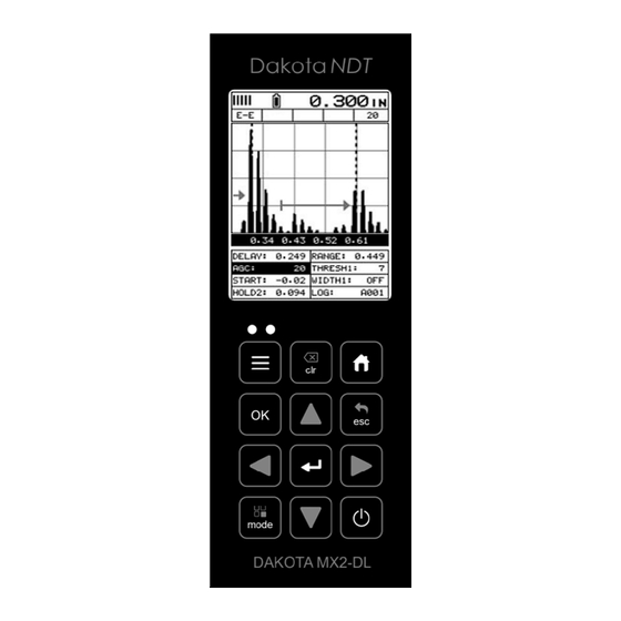
CHAPTER TWO QUICK STARTUP GUIDE Turn the MX2-DL on and off using the switch located on the bottom right corner of the keypad. When MX2-DL is initially turned on, a flash logo and blinking lights will be displayed prior to entering into the main measurement screen. - Page 7 MX2-DL is reliably measuring the same value 250 times per second (250 Hz). B. Battery Icon – Indicates the amount of battery life the MX2-DL has remaining. C. Velocity – The material velocity value the MX2-DL is currently using or calibrated for.
- Page 8 Dakota NDT M. Hot Menu items – We call this menu section our “hot menu”, as these items are the most commonly adjusted features, requiring quick access from the user. They can be displayed and scrolled by pressing the key at anytime.
-
Page 9: Selecting The Transducer Type
MX2-DL A/B Scan Thickness Gauge 2.2 Selecting the Transducer Type The MX2-DL is equipped with a transducer list of all of the dual element transducer options that can be connected to the gauge. These are dual element transducers with different diameters and frequencies, depending on the material and application requirements. -
Page 10: Probe Zero & Calibration
Dakota NDT 2) Use the arrow keys to scroll through the sub menu items until TYPE is highlighted. 3) Press the key to display the table/list of transducers. 4) Use the arrow keys to highlight the transducer type currently connected to the gauge. - Page 11 MX2-DL A/B Scan Thickness Gauge The next steps are to perform a probe zero and calibrate the MX2-DL to the material and transducer selected. If the sound velocity is unknown, the MX2-DL can be calibrated to a known thickness sample. The procedures are outlined as follows:...
- Page 12 Note: The value that is displayed will change depending on the current velocity setting in the MX2-DL. Disregard the number that is displayed. It is not important. What is important is accurately performing the steps outlined above to insure reliability of the probe zero calculation.
- Page 13 MX2-DL A/B Scan Thickness Gauge Note: Be sure a probe zero has been performed prior to calibration. 1) Physically measure an exact sample of the material, or a specific location directly on the material using a set of calipers or a digital micrometer.
-
Page 14: Measure
If the thickness is not correct, repeat the steps above. 2.4 Measure The MX2-DL is now ready to measure. There are four different measurement view options, each with a specific purpose – Digits, RF, RECT, & B-Scan. The steps... - Page 15 DIGITS: Displays the digital thickness value using a large font size. This view is useful when the MX2-DL is being used as a basic thickness gauge. RF: Displays the actual waveform signal, much like an oscilloscope, from the reflection of the opposite surface, pit, flaw, crack or void. This view shows both the positive and negative peaks, and is often used to fine tune the scope settings, prior to inspection.
- Page 16 Dakota NDT polarity or “phase” displayed. This is typically determined by first using RF view to select the most optimal polarity “phase”, to fine tune the scopes settings. The RECT view is commonly used as the primary “flaw detection” view.
- Page 17 MX2-DL A/B Scan Thickness Gauge move left, until the either the DELAY (START) or RANGE (DEPTH) cell is highlighted. 2) Use the arrow keys to scroll the DELAY (START) and RANGE (DEPTH) values. 3) Repeat steps 1 & 2 until the range is correctly being displayed.
- Page 18 Dakota NDT 5) Press the key to set the DELAY (START) and WIDTH (DEPTH) value and return to the measure screen, or to cancel entering the DELAY (START) or WIDTH (DEPTH) value. 6) Finally, press the key to return to the measurement screen and begin taking readings.
-
Page 19: Chapter Three Keyboard, Menu, & Connector Reference
CHAPTER THREE KEYBOARD, MENU, & CONNECTOR REFERENCE 3.1 Menu Key (Operation & Sub Menus) The Menu key activates the primary menu structure containing 8 menu tab groups. These tab groups then contain sub menu items, or functions. The sub menu items have been organized in tab groups according to how closely they are related to the individual tab group names. - Page 20 Dakota NDT Activating and Getting Around in the Menu Items 1) Press the key once to activate the menu items tab. Press the key multiple times to tab right, and the key multiple times to tab left until the desired tab group is highlighted and displaying the submenu items.
-
Page 21: Probe - Menu
If the MX2-DL is not zeroed correctly, all of the measurements made using the MX2-DL may be in error by some fixed value. The MX2-DL is equipped with an optional automatic or manual zero feature. Refer to the section on page 32, for an explanation of this important procedure. -
Page 22: Tune - Menu
The options are Spike, Thin, and Wide. Refer to page 74 for a further explanation. GAIN: The MX2-DL has 46dB gain range from (10 to 56 dB). This feature is used to increase/decrease the power or amplitude of the signal and. This might easily be considered as similar to turning the volume up or down on a stereo receiver. -
Page 23: Gt1 - Menu
MX2-DL A/B Scan Thickness Gauge adjusted. The adjustment range is an arbitrary 1-20 scale, the higher the number the larger the dynamic range. Refer to page 56 for further info. 3.6 GT1 – Menu GATE1: Gates allow the user to view a specific measurement range, or sections of the waveform, and ignore others. -
Page 24: Data - Menu
Refer to page 117 for further info. DEFAULT SETUP: Loads a basic default setup. Use only as a last resort when the setups in the MX2-DL have been corrupted and a computer is not accessible. Refer to page 119 for further info. -
Page 25: Util (Utilities) - Menu
MX2-DL. Refer to page 82 for further info. SHOW DATE: Gives the user the ability to display the date and time in the waveform area of the MX2-DL. The options are OFF, DATE, TIME, BOTH. Refer to page 84 for further info. -
Page 26: Clr (Clear) Key
The primary function of the OK key is confirmation of a change or selection. Additionally, the OK key also toggles the Hot Menu area to a large digits display while in measurement mode. If the MX2-DL is displaying a grid log, the OK key toggles an advance to row number option. -
Page 27: Multi Mode Key
MX2-DL A/B Scan Thickness Gauge The ENTER key is used in the overall menu selection process, to activate list and edit boxes, display and save measurements to grid file location. 3.18 MULTI MODE Key The MULTI MODE key opens a measurement mode screen that lists all the modes available for the transducer selected. -
Page 28: Top & Bottom End Caps
C female connector. It is designed to connect directly from the MX2-DL to a standard USB type A port on a PC. The cable supplied with the MX2-DL is a USB type C to a USB type A (pt# N-003-0330). -
Page 29: Chapter Four Principals Of Ultrasonic Measurement
CHAPTER FOUR PRINCIPALS OF ULTRASONIC MEASUREMENT 4.1 Time versus thickness relationship Ultrasonic thickness measurements depend on measuring the length of time it takes for sound to travel through the material being tested. The ratio of the thickness versus the time is known as the sound velocity. In order to make accurate measurements, a sound velocity must be determined and entered into the instrument. -
Page 30: Temperature
MX2-DL and selecting the ‘zero transducer’ option in the “PRB” menu. Errors can result from surface coatings and temperature gradients in pulse-echo mode. - Page 31 MX2-DL A/B Scan Thickness Gauge detecting small defects. Also, the surface of the test material does not have to be as flat in order to obtain good measurements. Dual element transducers are normally used in pulse-echo mode for finding defects, and in echo-echo mode for through coating measurements.
-
Page 32: Chapter Five Selecting The Measurement Mode
5.2 Which mode & transducer do I use for my application? High penetration plastics and castings The most common mode for these types of applications is pulse-echo. The MX2-DL has been optimized for cast materials. Cast iron applications require 1 - 5MHz frequencies, and cast aluminum requires a 10MHz frequency. -
Page 33: Factory Setup Chart
MX2-DL A/B Scan Thickness Gauge with extra resolution. The higher frequencies provide greater resolution and a lower minimum thickness rating overall. High temperature Use and select a special 2.25MHz and 5 MHz High temperature transducer for these types of applications. Both pulse-echo and echo-echo modes will also work for these applications. -
Page 34: Chapter Six Making Measurements
MAKING MEASUREMENTS 6.1 Selecting the Transducer Type The first step in using the MX2-DL is to plug the transducer into the gauge and power up the unit to display the main measurement screen. The diameter and frequency should be noted in order to select a transducer from the list of probes in the gauge. - Page 35 MX2-DL A/B Scan Thickness Gauge 3) Press the key to display the list of transducer options. 4) Press the arrow keys to scroll through the transducer list until the appropriate type is highlighted. 5) Press the key to select the transducer type and display overwrite confirmation screen.
-
Page 36: Probe Zero
If the MX2-DL is not zeroed correctly, all measurements may be in error by some fixed value. In order to perform a zero, the gauge must be set to pulse-echo measurement mode. - Page 37 MX2-DL A/B Scan Thickness Gauge 2) Press the key once to activate the menu items tab. Press the key multiple times to tab right and the key multiple times to tab left until the PRB menu is highlighted and displaying the submenu items.
-
Page 38: Material Calibration
6.3 Material Calibration In order for the MX2-DL to make accurate measurements, it must be set to the correct sound velocity of the material being measured. Sound will travel at different speeds in different material types. For example, the velocity of sound through steel is about 0.233 inches per microsecond, versus that of aluminum, which is about 0.248... - Page 39 MX2-DL A/B Scan Thickness Gauge 1) Press the key once to activate the menu items tab. Press the key multiple times to tab right and the key multiple times to tab left until the CAL menu is highlighted and displaying the submenu items.
- Page 40 As previously discussed, the MX2-DL has a one or two point calibration option. The one point calibration option is most suited for linearity over large ranges, as noted above.
- Page 41 MX2-DL A/B Scan Thickness Gauge items tab. Press the key multiple times to tab right and the multiple times to tab left until the CAL menu is highlighted and displaying the submenu items. 3) Use the arrow keys to scroll through the sub menu items until MATL 1PT is highlighted.
- Page 42 (6.35mm), the user would perform a one point calibration on a known thickness sample close to .250” (6.35mm), followed by a two point calibration close to .080” (2.03mm). When a two point calibration is performed, the MX2-DL calculates the zero and the velocity. The following steps outline this procedure:...
- Page 43 MX2-DL A/B Scan Thickness Gauge multiple times to tab left until the CAL menu is highlighted and displaying the submenu items. 3) Use the arrow keys to scroll through the sub menu items until MATL 2PT is highlighted. 4) Press the key to display the Digits Edit Box.
- Page 44 Dakota NDT Basic Material Type If the material velocity is unknown, and a sample thickness cannot be taken from the material, the user may opt to choose a basic material type from a list with approximate velocity values according to various material types. It’s important to note that these velocities will not always be an exact representation of the material being tested.
- Page 45 MX2-DL A/B Scan Thickness Gauge 3) Press the key to display the list of material types. 4) Press the arrow keys to scroll through the material list until the appropriate material is highlighted. 5) Press the key to overwrite the material type and display the menu items with the new material type selected.
-
Page 46: Chapter Seven Using The Display Options
Scan, B-Scan, and Large Digits). We’ll take a better look at these options in this chapter. Note: In order to recall and use the new adjustments made to the MX2-DL at a later time, the user must save the modified settings in one of the setup locations prior to... -
Page 47: Display Views
MX2-DL is reliably measuring the same value 250 times per second, depending on which measurement mode and features are enabled. B. Battery Icon – Indicates the amount of battery life the MX2-DL has remaining. C. Velocity – The material velocity value the MX2-DL is currently using or calibrated for. - Page 48 Dakota NDT E. Digital Material Thickness Value – Extra large font size for viewing ease. F. Scan Bar – Another view of material thickness in a deflection style horizontal bar. This is another visual tool that would enable the user the ability to see thickness changes during high speed scans from flaws and pits.
- Page 49 MX2-DL is reliably measuring the same value 250 times per second, depending on which measurement mode and features are enabled. B. Battery Icon – Indicates the amount of battery life the MX2-DL has remaining. C. Velocity – The material velocity value the MX2-DL is currently using or calibrated for.
- Page 50 When all the vertical bars are fully illuminated and the last digit on the digital thickness value is stable, the MX2-DL is reliably measuring the same value 3 to 200 times per second, depending on which measurement mode and features are enabled.
- Page 51 I. Units – The current measurement units being used (English, Metric). J. Velocity – The material velocity value the MX2-DL is currently using or calibrated for. Displayed in either English or Metric units, depending on what units the gauge is set for.
- Page 52 When all the vertical bars are fully illuminated and the last digit on the digital thickness value is stable, the MX2-DL is reliably measuring the same value 3 to 200 times per second, depending on which measurement mode and features are enabled.
- Page 53 I. Units – The current measurement units being used (English, Metric). J. Velocity – The material velocity value the MX2-DL is currently using or calibrated for. Displayed in either English or Metric units, depending on what units the gauge is set for.
-
Page 54: Changing Display Options
Dakota NDT 7.2 Changing Display Options The following procedure outlines how to select or toggle display options: Display Views 1) Press the key once to activate the menu items tab. Press the key multiple times to tab right, and the key multiple times to tab left, until the DISP menu is highlighted and displaying the submenu items. - Page 55 The Delay (B-Start) represents the left side of the display, and can be adjusted to start at any thickness value within the overall range of the MX2-DL. The value the Delay (B-Start) is set too, is the minimum thickness value that will be displayed on the screen.
- Page 56 Dakota NDT Adjusting Delay (B-Start) using the Hot Menus 1) Press the key once to activate measure menu items. Press the key multiple times to move right and the key multiple times to move left, until the DELAY cell is highlighted.
- Page 57 Therefore, the Range (B-Depth) is the overall area, from the delay, that will be viewable on the screen. The MX2-DL digitizer will round up from the Range (B-Depth) that’s entered. Therefore, if the Range (B-Depth) is set at 1.0”, the digitizer will round this value up to the next adjustment available.
- Page 58 Dakota NDT 2) Press the arrow keys to scroll the highlighted value. 3) Alternatively, press the key to display the Digits Edit Box. 4) Press the arrow keys to scroll the highlighted value. 5) Press the arrow keys to scroll the digit locations.
- Page 59 Adjusting the B-Scan Speed The MX2-DL has the capability to adjust the the scrolling speed of the time based B- Scan displayed in the gauge. The procedures to adjust the speed are outlined below: Adjusting the B-Scan Speed 1) Press the key once to activate the menu items tab.
-
Page 60: Gain
This would be a good time to change the MX2-DL to lower gain setting and see if the reading settles down and becomes stable. - Page 61 Note: When the echo-echo thru-paint, or echo-echo-verify measurement modes are selected, the manual gain feature is disabled and grayed out in the menu items. In this mode, the MX2-DL switches to an automatic gain mode (AGC) that optimizes the gain setting automatically in the hardware of the MX2-DL.
- Page 62 Dakota NDT 3) Alternatively, press the key to display the Digits Edit Box. 4) Press the arrow keys to scroll the highlighted value. 5) Press the arrow keys to scroll the digit locations. 6) Repeat steps 4 & 5 until the GAIN value is correctly displayed.
- Page 63 MX2-DL A/B Scan Thickness Gauge 2) Use the arrow keys to scroll through the sub menu items until GAIN is highlighted. 3) Press the arrow keys to scroll the value. When the correct Gain is being displayed, proceed to step 8.
-
Page 64: Threshold
This level can be used in conjunction with the gain. Example: suppose the user can visually see a potential flaw on the display, but the MX2-DL is not detecting on the flaw because the Gain is too low, or the Threshold to high. The Threshold level can be decreased (lower sensitivity) in order to detect signals with lower amplitudes. - Page 65 MX2-DL A/B Scan Thickness Gauge 3) Alternatively, if the correct Threshold is not being displayed, press the key to display the List Box. 4) Use the arrow keys to scroll through the List Box items until the correct THRESHOLD is highlighted.
- Page 66 Dakota NDT 4) Alternatively, press the key to display the Digits Edit Box. 5) Press the arrow keys to scroll the highlighted value. 6) Press the arrow keys to scroll the digit locations. 7) Repeat steps 5 & 6 until the Threshold number is correctly displayed.
-
Page 67: Understanding The Features Of The Gates
The sections that follow are procedures for using the features associated with the gates. There are two gates in the MX2-DL. A single gate is active in pulse-echo, while both gates are active in echo-echo mode. The following diagram illustrates the... - Page 68 Dakota NDT Using the Gates Noise Blocked A = Surface noise or transducer ring. D = Threshold level B = Bad detection E = Adjust sensitivity C = Good detection F = Gate Start: This feature is only available to gate 1 and determines where the gate will start in terms of thickness.
-
Page 69: Adjusting The Gates
MX2-DL A/B Scan Thickness Gauge 7.7 Adjusting the Gates Now that the features of the gates are understood, this section focuses on how to make adjustments to those features. They can be adjusted from both the ‘hot menus’ as well as from the drop down tabbed menus. Both procedures are outlined as... - Page 70 Dakota NDT 3) Press the key at any time to enter the exact value required (fine adjust). 4) Press the arrow keys to scroll the highlighted value. 5) Press the key to save the value, or key to abort changes.
- Page 71 MX2-DL A/B Scan Thickness Gauge 7) Use the arrow keys to scroll through the List Box items until the correct threshold is highlighted. 8) Press the key to return to the measure screen and Hot Menu items. 9) Press the arrow keys to scroll the highlighted value.
- Page 72 Dakota NDT 4) Alternatively, press the key to display the Digits Edit Box. 5) Press the arrow keys to scroll the highlighted value. 6) Press the arrow keys to scroll the digit locations. 7) Repeat steps 5 & 6 until the (X) number is correctly displayed.
-
Page 73: Chapter Eight Thru Paint Measurement Technique
The first thing to note in this section is that by selecting the transducer type from the list of probes stored in the MX2-DL, a basic echo-echo thru paint configuration is recalled from memory. Each of the ‘high damped’ transducers in the list contain pre- configured echo-echo settings. - Page 74 Note: Once the values of the fields have been changed or modified, these changes must be saved to a setup location prior to powering the MX2-DL off. Failure to do so will result in losing your changes. Refer to page 111 for additional information on setups.
-
Page 75: Chapter Nine Additional Features Of The Mx2-Dl
We’ve added a couple of graphic interface features to the MX2-DL , accommodate customer requests we’ve received in the past. These features only serve as cosmetic items, and do not change the functionality of the MX2-DL in any way. RECT Wave:... -
Page 76: Polarity
The detect mark is another look and feel option for displaying the detection indicator. 9.2 Polarity The MX2-DL is equipped with an option to select the polarity, or phase +/-, for the purpose of detection. The phase can be a very valuable feature to have when the... - Page 77 (B). Therefore, if the user was measuring thick attenuative material, and the amplitude of (B) decreased substantially, the MX2-DL would lose the first cycle (B) and peak jump to the second cycle (F). The detect (A), would move to (F), resulting in incorrect measurements.
-
Page 78: Pulse
Important: Be sure to do a Probe Zero after changing the polarity! 9.3 Pulse The MX2-DL has an adjustable pulse width option. Pulse width, refers to the duration of time the pulser is left on. This time results in increased energy sent into the test material. -
Page 79: Auto Find
Suppose the MX2-DL is currently setup with a delay of 0.0” and a width of 1.0”, and the user is measuring material thickness of 2.5”. The MX2-DL will make the correct measurement and display it digitally. -
Page 80: High Speed Scan
9.5 High Speed Scan The High Speed Scan feature of the MX2-DL increases the overall repetition rate to a maximum of 250Hz with a high speed screen refresh rate of 25 times a second. This feature enables a user to make scanned passes over an arbitrary length of the test material, while still maintaining a reasonable representation of thickness over the scanned area or region. -
Page 81: Alarm Mode
9.6 Alarm Mode The Alarm Mode feature of the MX2-DL provides the user with a method of setting tolerances, or limits, for a particular application requirement. This feature may be used for a variety of applications to verify the material is within the manufacturer specifications. - Page 82 Dakota NDT application requirements. The procedures to use the ALARM MODE feature are outlined below: Toggle Alarm (on/off) 1) Press the key once to activate the menu items tab. Press the key multiple times to tab right, and the key multiple times to tab left, until the UTIL menu is highlighted and displaying the submenu items.
- Page 83 MX2-DL A/B Scan Thickness Gauge 1) Assuming the ALARM is ON, use the arrow keys to scroll through the sub menu items until ALARM LOW is highlighted. 2) Press the arrow keys to scroll the value. When the correct alarm value is being displayed, proceed to step 7.
-
Page 84: Differential Mode
ALARM HIGH limit using the same procedures. 9.7 Differential Mode The Differential Mode of the MX2-DL provides the user with the ability to set a nominal value, according to what the expected thickness should be, and measure the +/- difference from the nominal value entered. -
Page 85: Key Click
MX2-DL A/B Scan Thickness Gauge 4) Continue on to the next section “Setting the Differential Value”. Setting the Differential Value 1) Assuming DIFFERENTIAL has been enabled and a value is being displayed to the right of the DIFFERENTIAL label, press the key to display the Digits Edit Box. -
Page 86: Set Date & Time
Dakota NDT When a key is pressed on the MX2-DL keypad, the user can control whether or not an audible beep is sounded and at what volume level, if any. The procedure for this feature/preference is outlined below: Setting the Key Click 1) Press the key once to activate the menu items tab. - Page 87 MX2-DL A/B Scan Thickness Gauge 1) Press the key once to activate the menu items tab. Press the key multiple times to tab right and the key multiple times to tab left until the UTIL menu is highlighted and displaying the submenu items.
-
Page 88: Show Date & Time
9.10 Show Date & Time The MX2-DL can be configured to show the date & time in the active A-Scan window as needed or preferred (off/date/time/both). The procedure for activating and displaying the above options are outlined below: Live Time &... -
Page 89: Freeze & Capture
.tif (tagged image) file format that can be opened using any graphics viewer. With the storage capacity of the MX2-DL the user can store as many screens shots as needed. It should also be mentioned that this feature is immediately activated on boot up. -
Page 90: Capture Viewer
The capture viewer enables a user to view any of the saved screen captures on the SD card, using the MX2-DL. This is handy if a PC isn’t available, but the user has a need to review the screen shots captured. - Page 91 MX2-DL A/B Scan Thickness Gauge 1) Press the key once to activate the menu items tab. Press the key multiple times to tab right and the key multiple times to tab left until the XFER menu is highlighted and displaying the submenu items.
-
Page 92: Chapter Ten Data Storage - Setup, Edit, & View Files
Multiple grids can be created and stored until the MX2-DL’s memory is full. If the user attempts to store a new file in the MX2-DL and the size of the file exceeds the capacity of memory, the MX2-DL will respond with an error message indicating that the memory is unable to store the new file. -
Page 93: Creating A New Grid
MX2-DL A/B Scan Thickness Gauge 10.2 Creating a new Grid Grid Name 1) Press the key once to activate the menu items tab. Press the key multiple times to tab right, and the key multiple times to tab left, until the DATA menu is highlighted and displaying the submenu items. - Page 94 Dakota NDT 5) Press the key to activate the Alpha Edit Box. 6) Use the arrow keys to highlight the appropriate alpha characters. 7) Press the key to select a character and advance to the next field of the grid name.
- Page 95 MX2-DL A/B Scan Thickness Gauge 1) Use the arrow keys to scroll through the setup options until NOTE is highlighted. 2) Press the key to activate the Alpha Edit Box. 3) Use the arrow keys to highlight the appropriate alpha characters.
- Page 96 Dakota NDT 7) Press the key to save the Grid and return to the setup list, or cancel entering a Note. Setting the Coordinates or Start & Stop ID’s A grid is defined by using coordinates to define the Top Left and the Bottom Right corners of the grid.
- Page 97 MX2-DL A/B Scan Thickness Gauge 1) Use the arrow keys to scroll through the setup list until TOP is highlighted. 2) Press the key to activate the Coordinate Edit Box. 3) Use the arrow keys to scroll the Columns, and the arrow keys to scroll the Rows.
- Page 98 Dakota NDT 1) Use the arrow keys to scroll through the setup list until LOWER is highlighted. 2) Press the key to activate the Coordinate Edit Box. 3) Use the arrow keys to scroll the Columns, and the arrow keys to scroll the Rows.
- Page 99 MX2-DL A/B Scan Thickness Gauge 4) Press the key to select the coordinate and return to the setup list, or to cancel the selection and return to the setup list. Note: If there is not enough memory available to create the grid or sequential...
- Page 100 Dakota NDT Auto Increment Direction The Auto Increment feature gives the user the ability to specify which direction to advance the cursor after storing a reading. 5) Use the arrow keys to scroll through the setup list until INCR. DIR is highlighted.
- Page 101 MX2-DL A/B Scan Thickness Gauge 1) Use the arrow keys to scroll through the setup list until CREATE GRID is highlighted. 2) Press the key to save the grid display the confirmation screen. 3) Press the key to save the Grid, or the key to cancel the setup and return to the DATA menu.
-
Page 102: Storing A Reading
Dakota NDT 10.3 Storing a reading Now that a grid or sequential log has been created, it’s time to make some measurements and store the readings. The following procedures outline this process: Storing Data Note: Once the gird has been created it will automatically be displayed following the create confirmation screen. -
Page 103: Viewing Stored Readings
If the gauge is powered off, the will automatically open the file when powered on. 10.4 Viewing stored readings It is sometimes necessary to go back and view the stored readings and B-Scans using the MX2-DL without a PC. The following procedures outline this process:... - Page 104 Dakota NDT Viewing Stored Readings & A/B Scans 1) Press the key once to activate measure menu items. Press the key multiple times to move right and the key multiple times to move left until the LOG cell is highlighted.
-
Page 105: Deleting Grids (Files)
MX2-DL A/B Scan Thickness Gauge indicated by displaying a MEM in the top left corner of the measurement screen. 4) The user may opt to clear a specific reading and save a new one at any time. Press the key in the appropriate cell location to clear the... - Page 106 Dakota NDT 2) Use the arrow keys to scroll through the sub menu items until DELETE ONE FILE is highlighted. 3) Press the key to display the File List Box. 4) Use the arrow keys to scroll through the stored Files until the target File to delete is highlighted.
- Page 107 MX2-DL A/B Scan Thickness Gauge 2) Use the arrow keys to scroll through the sub menu items until DELETE ALL DATA is highlighted. 3) Press the key to activate the confirmation screen. 4) Press the key to delete All Files from memory, or the key to abort.
-
Page 108: Editing A Grid (File)
Dakota NDT 10.6 Editing a Grid (File) Once a grid has been created and saved to memory, the user can edit the Comments or Increment Direction at a later time. The following procedures outline this process: Editing a Grid 1) Press the key once to activate the menu items tab. - Page 109 MX2-DL A/B Scan Thickness Gauge Note: If editing the INCR. DIR, simply use the arrow keys to scroll NONE, NORTH, EAST, SOUTH, WEST for a Grid, or INC, DEC for a Seq Log. Proceed to step 10. 5) Press the key to activate the Alpha Edit box –...
- Page 110 Dakota NDT 10) Press the arrow key to highlight SAVE CHANGES, and the key to activate the confirmation screen. 11) Press the key to save the changes or the key to cancel editing the file parameters. 12) Press the key to return to the measurement screen.
-
Page 111: Changing The Active File - Open
The user may have transferred grid templates from a PC to the MX2-DL, or setup grids using the MX2-DL at an earlier time. The name of the currently active file is always displayed at the top of the Grid Box in measurement mode (refer to photo below). - Page 112 Dakota NDT 2) Use the arrow keys to scroll through the sub menu items until OPEN is highlighted. 3) Press the key to display the Grid/Seq List Box. 4) Use the arrow keys to scroll through the grids until the target...
-
Page 113: Closing An Active File - Close
MX2-DL A/B Scan Thickness Gauge 5) Press the key to activate the confirmation screen. 6) Press the key to load the file from memory. 7) Press the key to return to the measure screen. 10.8 Closing an active File - Close A user might not have a current requirement to store measurements, but a file is currently open or active and needs to be closed. - Page 114 Dakota NDT 2) Use the arrow keys to scroll through the sub menu items until CLOSE is highlighted. 3) Press the key to close the active file. Note: Following the key press, the CLOSE text will be grayed out indicating the file has been close and is...
-
Page 115: Chapter Eleven Setups - Create, Store, Edit, & Recall
The MX2-DL can store up to 64 custom setups. These setups can be bi- directionally transferred to and from a PC. Therefore, the user can save as many setups as necessary for all their individual applications requirements. - Page 116 Dakota NDT 1) Press the key once to activate the menu items tab. Press the key multiple times to tab right and the key multiple times to tab left until the SETUP menu is highlighted and displaying the submenu items.
-
Page 117: Saving A Setup
11.3 Saving a Setup Once the MX2-DL parameters and features have be adjusted for an application, the user may elect to save these setting to a specific setup location for future use. This can potentially save time and reduce error between users. - Page 118 Dakota NDT 1) Press the key once to activate the menu items tab. Press the key multiple times to tab right and the key multiple times to tab left until the SETUP menu is highlighted and displaying the submenu items.
- Page 119 MX2-DL A/B Scan Thickness Gauge 4) Press the arrow keys to scroll the Name and Note parameters. 5) When the parameter to edit is highlighted, press the key to activate the Alpha Edit Box. 6) Use the , and arrow keys to scroll through the...
- Page 120 Dakota NDT 9) Use the arrow keys to scroll to and highlight SAVE SETUP. 10) Press the key to activate the Setup List Box. 11) Use the arrow keys to scroll through the setups until the target location to save the Setup is highlighted.
-
Page 121: Deleting A Saved Setup
MX2-DL A/B Scan Thickness Gauge 12) Press the key to activate the confirmation screen. 13) Press the key to save the Setup, or to cancel saving the Setup. 14) Finally, press the key to return to the measurement screen. Note: The Name and Comments of the Setup can be edited at any time by simply repeating the Save Setup routine described above. - Page 122 Dakota NDT 1) Press the key once to activate the menu items tab. Press the key multiple times to tab right and the key multiple times to tab left until the SETUP menu is highlighted and displaying the submenu items.
-
Page 123: Using The Default Setup
7) Finally, press the key to return to the measurement screen. 11.5 Using the Default Setup The default setup feature was added to the MX2-DL to use, as a last resort, if there are no setups stored in the gauge –factory or otherwise. The only time this might... -
Page 124: Selecting A Language
3) Finally, press the key to return to the measurement screen. 11.6 Selecting a Language The MX2-DL is equipped with a language option. Currently, the only languages supported are English, Spanish, German, French, Hungarian, Czech, however the list continues to grow. Check with Dakota for an updated list. The steps to select one of... - Page 125 MX2-DL A/B Scan Thickness Gauge 1) Press the key once to activate the menu items tab. Press the key multiple times to tab right and the key multiple times to tab left until the SETUP menu is highlighted and displaying the submenu items.
-
Page 126: Chapter Twelve Using The Utility Software
12.5 Upgrading the MX2-DL The MX2-DL can be upgraded to the latest revision of firmware at any time. Simply download the latest version posted on the Dakota NDT website, copy the upgrade file to the main drive directory MX2-DL, and use the upgrade utility located in the XFER menu. - Page 127 MX2-DL A/B Scan Thickness Gauge Upgrading the Firmware 1) Press the key once to activate the menu items tab. Press the key multiple times to tab right and the key multiple times to tab left until the XFER menu is highlighted and displaying the submenu items.
-
Page 128: Appendix A - Velocity Table
APPENDIX A - VELOCITY TABLE Material sound velocity sound velocity in/us Aluminum 0.2510 6375 Beryllium 0.5080 12903 Brass 0.1730 4394 Bronze 0.1390 3531 Cadmium 0.1090 2769 Columbium 0.1940 4928 Copper 0.1830 4648 Glass (plate) 0.2270 5766 Glycerine 0.0760 1930 Gold 0.1280 3251 Inconel... - Page 129 MX2-DL A/B Scan Thickness Gauge 0.1310 3327 Titanium 0.2400 6096 Tungsten 0.2040 5182 Uranium 0.1330 3378 Water 0.0580 1473 Zinc 0.1660 4216 Zirconium 0.1830 4648...
-
Page 130: Appendix B - Setup Library
APPENDIX B - SETUP LIBRARY Name Comment 1 Gn/AGC Velocity Enter Custom Name … … … … … … …... - Page 131 Warranty Statement Dakota NDT warrants the MX2-DL against defects in materials and workmanship for a period of two years from receipt by the end user. Additionally, Dakota NDT warrants transducers and accessories against such defects for a period of 90 days from receipt by the end user.
Need help?
Do you have a question about the MX2-DL and is the answer not in the manual?
Questions and answers